Have you ever struggled with parts that keep coming loose during assembly? I’ve seen many engineers face this frustrating challenge, leading to production delays and increased costs. Even worse, loose components can cause catastrophic failures in critical machinery, putting both equipment and operators at risk.
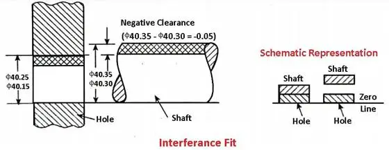
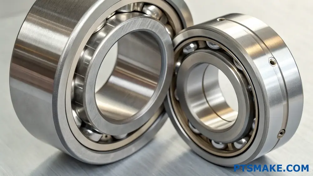
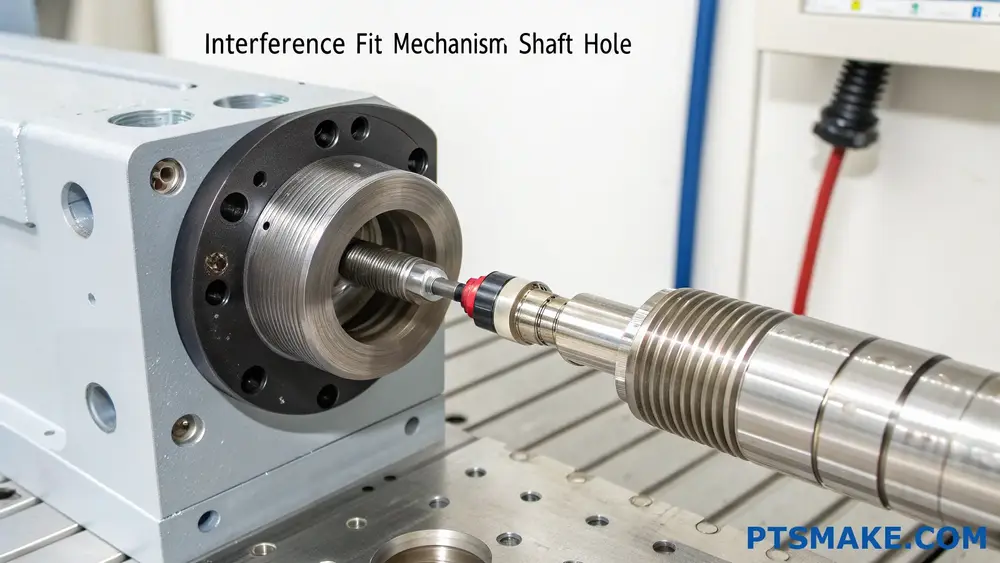
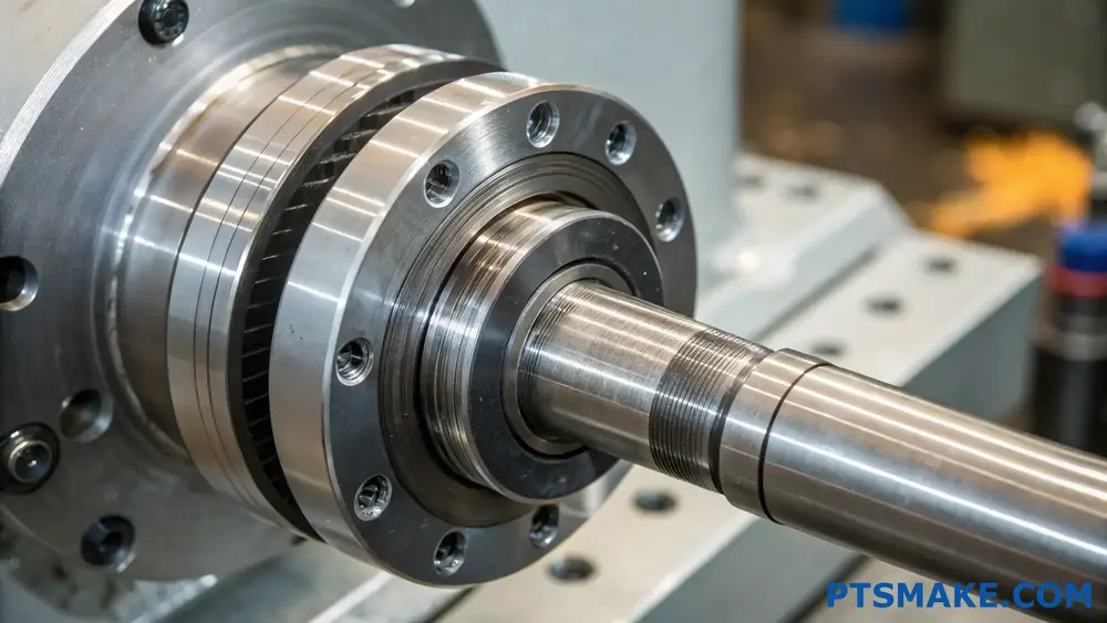
An interference fit, also known as a press fit or friction fit, is a fastening method where a slightly oversized part is forced into a smaller hole or mating component. This creates a strong, reliable connection through the friction between the two surfaces, eliminating the need for additional fasteners.
When it comes to interference fits, getting the calculations right is crucial. I’ve worked with countless precision parts at PTSMAKE, and I’ve seen how even a slight miscalculation can cause assembly issues or premature part failure. Let me share some essential insights about interference fits to help you make the right decisions for your next project.
What Is the Difference Between a Clearance and Interference Fit?
Have you ever encountered a situation where your precisely machined parts just won’t fit together properly? Or maybe you’ve struggled with components that seemed perfect on paper but either felt too loose or impossibly tight during assembly? These fitting issues can lead to costly project delays and rework.
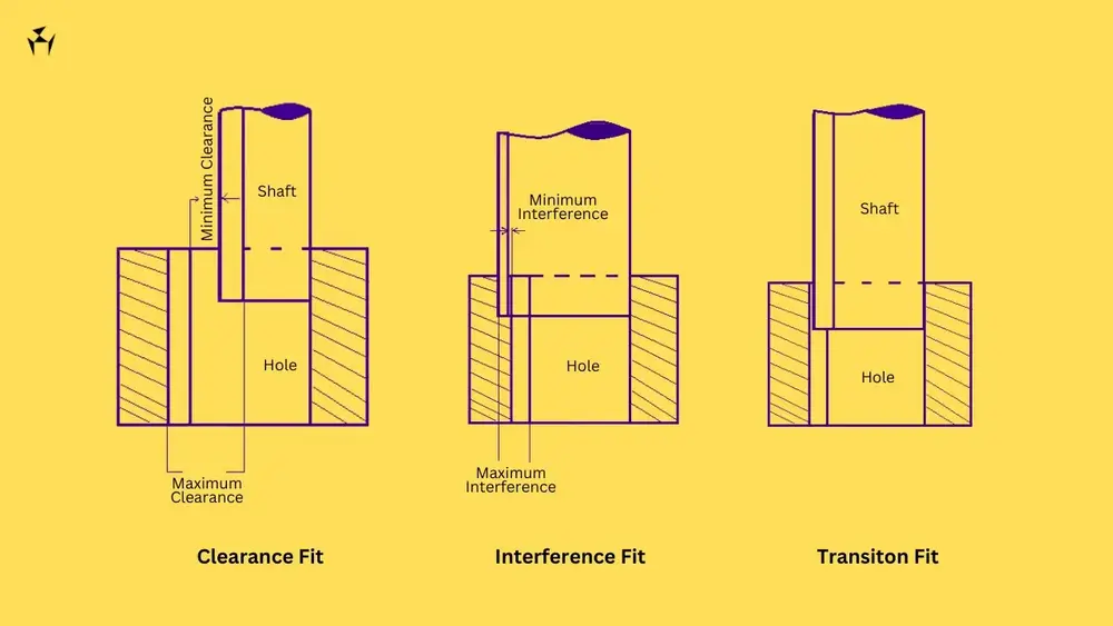
A clearance fit allows space between mating parts for free movement, while an interference fit creates a tight connection where the inner part is slightly larger than the outer part’s hole, requiring force for assembly. These fitting types serve different engineering purposes based on specific application requirements.
Understanding Basic Fit Types
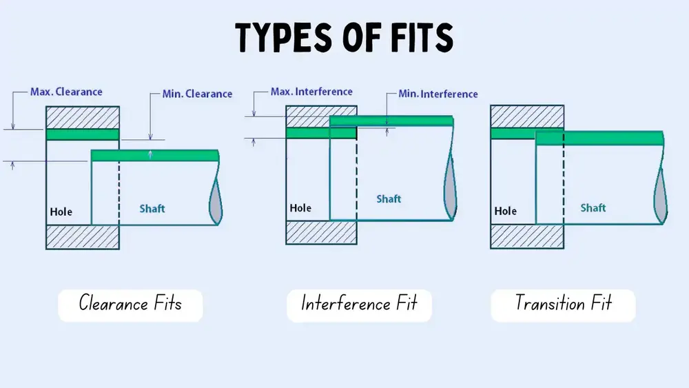
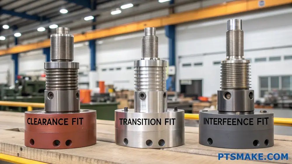
The concept of fits is fundamental in mechanical engineering and manufacturing. The three primary types of fits are:
Clearance Fit
- Parts can move freely
- Inner component is smaller than the outer hole
- Common in rotating assemblies
- Allows for lubrication
Interference Fit
- Parts are pressed together
- Inner component is larger than the outer hole
- Creates strong mechanical bond
- Requires force for assembly
Transition Fit
- Borderline between clearance and interference
- May have slight interference or clearance
- Depends on manufacturing tolerances
- Used for precise positioning
Measuring and Calculating Fits
The relationship between mating parts involves careful consideration of dimensional tolerancing1. Here’s how we typically measure different fits:
| Fit Type | Inner Part | Outer Hole | Typical Applications |
|---|---|---|---|
| Clearance | Smaller | Larger | Rotating shafts, bearings |
| Interference | Larger | Smaller | Wheel hubs, bushings |
| Transition | Nearly equal | Nearly equal | Positioning pins, guides |
Applications in Manufacturing
At PTSMAKE, I’ve observed various applications where proper fit selection is crucial. Let me share some common examples:
Clearance Fit Applications
- Rotating machinery components
- Sliding mechanisms
- Replaceable parts
- Assembly components requiring regular maintenance
Interference Fit Applications
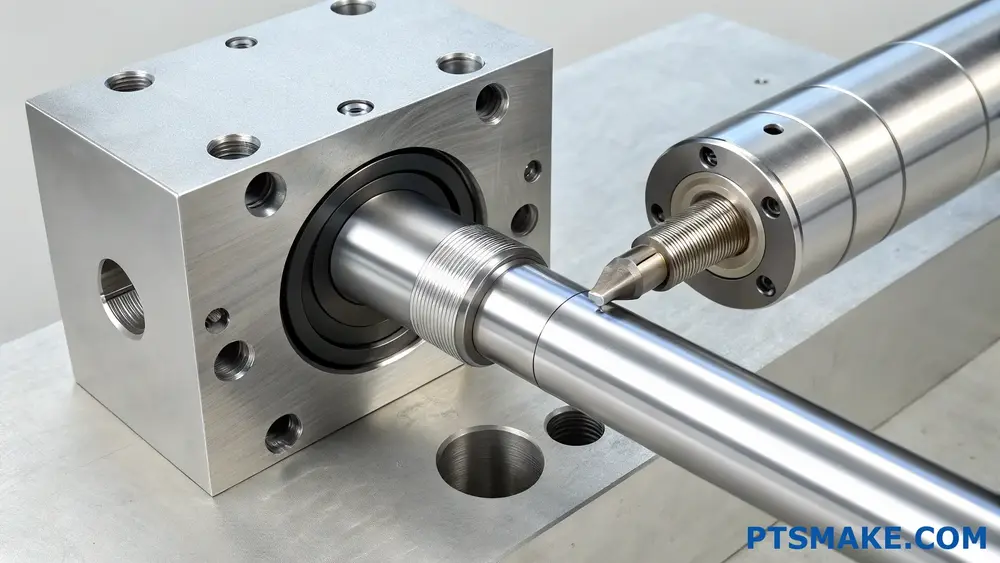
- Bearing installations
- Wheel and hub assemblies
- Permanent bushing installations
- Press-fit pins and dowels
Selecting the Right Fit
The choice between clearance and interference fits depends on several factors:
Functional Requirements
- Operating conditions
- Load requirements
- Movement needs
- Assembly/disassembly frequency
Material Considerations
- Thermal expansion properties
- Material strength
- Surface finish requirements
- Corrosion resistance
Manufacturing Capabilities
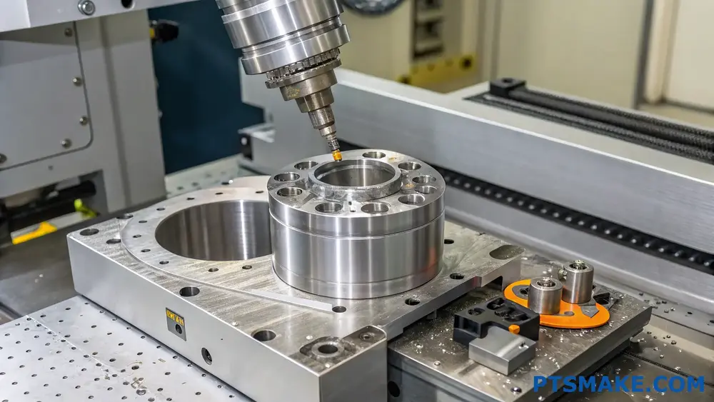
Our CNC machining capabilities at PTSMAKE allow us to achieve precise tolerances for both clearance and interference fits. Key considerations include:
- Machine precision capabilities
- Tooling requirements
- Measurement and inspection methods
- Surface finish specifications
Common Challenges and Solutions
Working with fits presents several challenges:
Assembly Issues
- Proper alignment during press fitting
- Prevention of component damage
- Correct tool selection
- Temperature control during assembly
Quality Control
- Accurate measurement techniques
- Consistent inspection procedures
- Documentation requirements
- Tolerance verification
Best Practices for Fit Selection
To ensure successful assembly and operation:
- Define functional requirements clearly
- Consider environmental conditions
- Account for material properties
- Plan for assembly and maintenance
- Verify manufacturing capabilities
- Establish quality control procedures
Temperature Effects on Fits
Temperature changes can significantly impact fit relationships:
- Thermal expansion differences
- Assembly temperature considerations
- Operating temperature ranges
- Material selection implications
Design Considerations
When designing for specific fits:
For Clearance Fits
- Calculate minimum clearance needed
- Consider lubrication requirements
- Account for wear allowance
- Plan for maintenance access
For Interference Fits
- Determine required holding force
- Calculate stress limitations
- Consider assembly methods
- Plan for possible future disassembly
Economic Implications
The choice of fit type affects:
- Manufacturing costs
- Assembly time and complexity
- Maintenance requirements
- Component lifetime
- Replacement frequency
How to Calculate Interference Fit for Precision Parts?
Have you ever faced the frustrating challenge of parts either being too loose or too tight during assembly? The wrong interference fit can lead to costly production delays, component failures, and endless headaches in manufacturing processes.
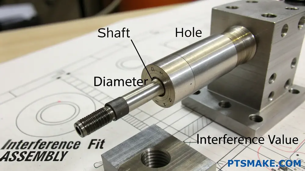
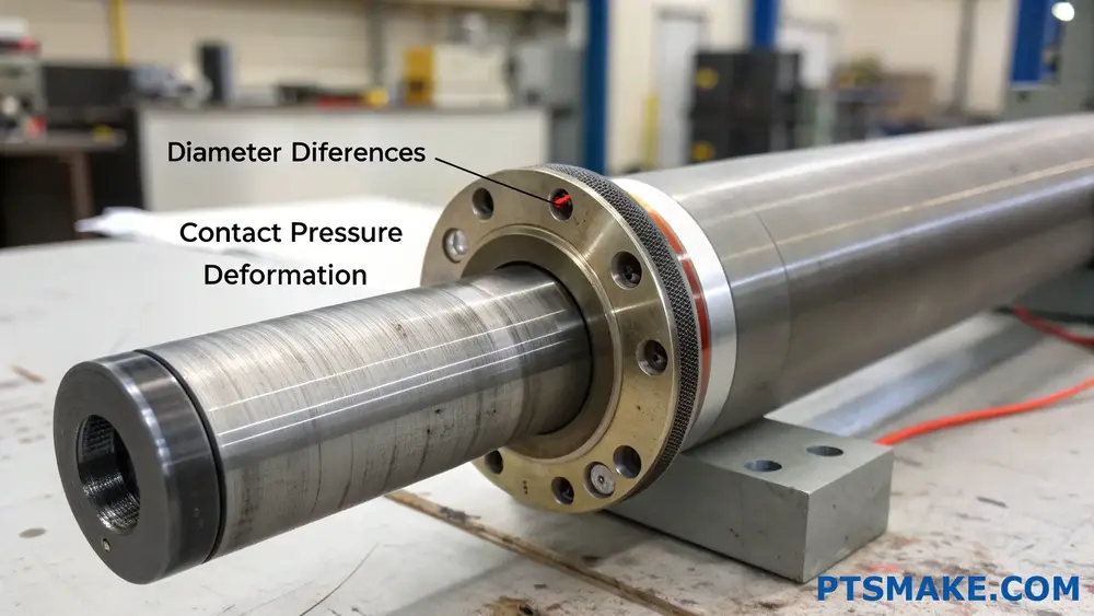
An interference fit calculation requires measuring the difference between mating parts’ dimensions, where the shaft is slightly larger than the hole. The typical calculation involves subtracting the hole diameter from the shaft diameter to determine the interference value.
Understanding the Basics of Interference Fit
When designing parts that require a secure, non-moving connection, understanding interference fit calculations is crucial. The basic principle involves creating a tight fit between two components by making one slightly larger than the other. This creates radial pressure2 between the parts when assembled.
Components of Interference Fit Calculation
The fundamental elements involved in calculating interference fit include:
- Shaft diameter (outer component)
- Hole diameter (inner component)
- Tolerance values
- Material properties
Mathematical Formula for Interference Fit
The basic formula for calculating interference fit is:
Interference = Shaft diameter - Hole diameterHowever, real-world applications require considering tolerance ranges. Here’s a more comprehensive approach:
| Parameter | Maximum | Minimum |
|---|---|---|
| Shaft Diameter | Dmax | Dmin |
| Hole Diameter | dmax | dmin |
| Interference | Imax = Dmax – dmin | Imin = Dmin – dmax |
Factors Affecting Interference Fit Calculations
Temperature Considerations
Temperature changes can significantly impact interference fit calculations. At PTSMAKE, we always consider thermal expansion coefficients when designing precision parts. The general formula for thermal expansion is:
ΔD = D × α × ΔTWhere:
- ΔD = Change in diameter
- D = Original diameter
- α = Coefficient of thermal expansion
- ΔT = Temperature change
Material Properties Impact
Different materials exhibit varying behaviors under interference fit conditions:
- Young’s Modulus affects deformation
- Poisson’s Ratio influences radial stress
- Surface finish affects assembly force
- Material hardness determines wear resistance
Practical Applications and Tolerances
Common Interference Ranges
| Application Type | Typical Interference (mm/mm) |
|---|---|
| Light Press Fit | 0.0001 – 0.0003 |
| Medium Press Fit | 0.0003 – 0.0005 |
| Heavy Press Fit | 0.0005 – 0.0008 |
Industry-Specific Requirements
Different industries require varying levels of interference fit:
- Automotive: Bearing seats and gear assemblies
- Aerospace: Turbine components and structural elements
- Medical: Precision instrument assemblies
- Industrial Machinery: Shaft-hub connections
Best Practices for Implementation
Quality Control Measures
To ensure successful interference fits:
- Use calibrated measuring instruments
- Maintain consistent temperature during measurement
- Consider surface finish requirements
- Document all measurements and calculations
Assembly Considerations
Proper assembly techniques are crucial:
- Alignment of components
- Lubrication requirements
- Assembly force monitoring
- Temperature control during assembly
Common Challenges and Solutions
Problem Prevention
Material selection issues
- Solution: Comprehensive material property analysis
- Consideration of operating conditions
Assembly difficulties
- Solution: Proper tooling and fixtures
- Controlled assembly environment
Quality consistency
- Solution: Regular measurement tool calibration
- Documented quality control procedures
Advanced Calculation Methods
Modern interference fit calculations often utilize computational methods:
Finite Element Analysis (FEA)
- Stress distribution analysis
- Deformation predictions
- Temperature effects simulation
Statistical analysis
- Tolerance stack-up calculations
- Process capability studies
- Quality control metrics
Safety and Reliability Considerations
When calculating interference fits, always consider:
- Maximum allowable stress
- Fatigue life requirements
- Operating environment conditions
- Safety factors for critical applications
At PTSMAKE, we employ advanced measurement systems and quality control processes to ensure precise interference fits for our clients’ components. This attention to detail has helped us maintain our position as a trusted partner in precision manufacturing.
How Tight Is an Interference Fit?
Have you ever struggled with parts that won’t stay together or components that keep coming loose? It’s frustrating when assemblies fail because the fit isn’t quite right, especially in critical applications where stability is non-negotiable.
An interference fit typically ranges from 0.0001 to 0.0004 inches per inch of diameter for metal components. The tightness depends on factors like material properties, operating conditions, and assembly requirements, ensuring parts remain securely joined without damage.
Understanding Interference Fit Tolerances
The tightness of an interference fit is crucial for maintaining assembly integrity. At PTSMAKE, we regularly work with various interference fits, and I’ve found that understanding the proper tolerances is essential for successful component mating.
Material Considerations
The choice of materials significantly impacts the interference fit requirements. Different materials exhibit varying levels of elastic deformation3 when pressed together:
| Material Combination | Typical Interference (inches per inch) |
|---|---|
| Steel on Steel | 0.0002 – 0.0004 |
| Aluminum on Steel | 0.0001 – 0.0003 |
| Brass on Steel | 0.0001 – 0.0003 |
| Plastic on Metal | 0.0003 – 0.0005 |
Temperature Effects
Temperature changes can significantly affect interference fits:
- Thermal expansion during operation
- Assembly temperature considerations
- Material-specific expansion rates
- Operating temperature ranges
Calculating Proper Interference
To determine the correct interference fit, several factors must be considered:
Component Size
The diameter of the mating parts directly influences the required interference:
| Component Diameter (inches) | Recommended Interference (inches) |
|---|---|
| 0.5 – 2.0 | 0.0005 – 0.001 |
| 2.0 – 4.0 | 0.001 – 0.002 |
| 4.0 – 6.0 | 0.002 – 0.003 |
Application Requirements
Different applications demand varying levels of interference:
Light-duty applications
- Minimal stress requirements
- Easy assembly/disassembly
- Lower interference values
Medium-duty applications
- Moderate load bearing
- Semi-permanent assembly
- Standard interference values
Heavy-duty applications
- High torque transmission
- Permanent assembly
- Maximum allowable interference
Assembly Considerations
Proper assembly techniques are crucial for successful interference fits:
Surface Preparation
- Clean, debris-free surfaces
- Proper surface finish
- Appropriate lubrication when needed
Assembly Methods
Press Fitting
- Controlled force application
- Even pressure distribution
- Proper alignment maintenance
Thermal Fitting
- Heating outer component
- Cooling inner component
- Temperature differential calculations
Quality Control Measures
To ensure proper interference fits, implement these quality control steps:
Pre-Assembly Inspection
- Dimensional verification
- Surface finish checking
- Material certification review
Post-Assembly Validation
- Alignment verification
- Functional testing
- Non-destructive testing when required
Common Challenges and Solutions
Excessive Interference
Problems:
- Component damage
- Assembly difficulties
- Material deformation
Solutions:
- Revised tolerance calculations
- Modified assembly methods
- Alternative material selection
Insufficient Interference
Issues:
- Joint failure
- Component loosening
- Performance degradation
Solutions:
- Tighter tolerance specifications
- Surface treatment options
- Design modifications
Industrial Applications
Different industries require specific interference fit considerations:
Automotive Industry
- Bearing installations
- Gear assemblies
- Shaft components
Aerospace Applications
- Turbine components
- Structural assemblies
- Critical fastening systems
Medical Device Manufacturing
- Precision instruments
- Implant components
- Surgical tools
Best Practices for Manufacturing
At PTSMAKE, we’ve developed comprehensive guidelines for interference fit manufacturing:
Design Phase
- Detailed tolerance analysis
- Material compatibility verification
- Assembly method planning
Manufacturing Phase
- Precise machining processes
- Regular quality checks
- Documentation maintenance
Assembly Phase
- Controlled environment
- Proper tooling selection
- Trained personnel
What Are the Advantages of Interference Fit?
Have you ever struggled with components that keep coming loose or rotating unexpectedly? These issues not only cause frustrating downtime but can also lead to catastrophic failures in critical machinery. The traditional fastening methods might not always provide the reliability you need.
Interference fit offers significant advantages including superior stability, excellent load-bearing capacity, and elimination of additional fastening components. This mechanical joining method creates a strong, reliable connection by forcing a larger part into a smaller hole, resulting in a secure assembly.
Understanding the Core Benefits of Interference Fit
Enhanced Structural Integrity
The primary advantage of interference fit lies in its ability to create exceptional structural integrity. When properly designed, the radial pressure4 generated between the mating parts creates a bond that often exceeds the strength of traditional fastening methods. At PTSMAKE, we’ve implemented this technique in numerous precision components, particularly in applications where mechanical stability is crucial.
Simplified Assembly Process
One of the most appealing aspects of interference fit is its streamlined assembly process:
| Assembly Feature | Benefit |
|---|---|
| No Additional Parts | Eliminates the need for screws, pins, or other fasteners |
| Reduced Assembly Time | Quick installation once parts are properly aligned |
| Lower Inventory Costs | Fewer components to stock and manage |
| Minimal Maintenance | No periodic tightening or adjustment required |
Superior Load Distribution
The uniform pressure distribution in interference fits provides excellent load-bearing capabilities:
- Evenly distributed stress across the entire contact surface
- Reduced risk of stress concentration points
- Enhanced resistance to both static and dynamic loads
- Better fatigue life compared to traditional fastening methods
Economic Advantages
Cost Reduction Opportunities
The economic benefits of interference fit extend beyond the initial assembly:
| Cost Factor | Impact |
|---|---|
| Material Costs | Reduced due to fewer components |
| Labor Expenses | Lower assembly and maintenance time |
| Warranty Claims | Decreased failure rates |
| Production Efficiency | Faster assembly processes |
Long-term Reliability
The durability of interference fit connections often results in:
- Extended component lifespan
- Reduced maintenance requirements
- Lower warranty-related expenses
- Improved customer satisfaction
Design Considerations
Material Selection
Proper material selection is crucial for successful interference fits:
- Material compatibility between mating parts
- Thermal expansion characteristics
- Surface finish requirements
- Hardness and yield strength considerations
Tolerance Control
Precise tolerance control is essential for optimal interference fit performance:
| Tolerance Factor | Requirement |
|---|---|
| Surface Finish | Ra 0.8-3.2 μm typical |
| Roundness | Within 0.01mm |
| Cylindricity | Within 0.02mm |
| Size Tolerance | IT6-IT7 grade |
Application Examples
Industrial Applications
Interference fits are widely used in various industrial applications:
- Bearing assemblies in rotating machinery
- Gear mounting on shafts
- Bushings in automotive components
- Precision alignment components
Critical Considerations
When implementing interference fits, several factors require attention:
- Temperature effects during assembly
- Proper alignment procedures
- Assembly force requirements
- Surface preparation methods
Best Practices for Implementation
Assembly Techniques
Successful interference fit assembly requires:
- Proper cleaning and preparation of mating surfaces
- Correct alignment before assembly
- Appropriate pressing equipment and fixtures
- Temperature control during assembly when necessary
Quality Control Measures
To ensure reliable interference fits:
| Control Measure | Purpose |
|---|---|
| Dimensional Inspection | Verify component sizes |
| Surface Analysis | Check finish quality |
| Assembly Force Monitoring | Ensure proper fit |
| Post-assembly Testing | Validate connection integrity |
At PTSMAKE, we maintain strict quality control standards for all interference fit components, ensuring optimal performance and reliability for our customers. Our advanced manufacturing capabilities allow us to achieve the precise tolerances required for successful interference fits across various applications.
What Are the 3 Types of Fits?
Have you ever struggled with parts that just won’t fit together properly? It’s frustrating when components either fit too loosely, causing wobble and wear, or too tightly, making assembly nearly impossible. This common challenge can lead to costly production delays and quality issues.
The three main types of fits in mechanical engineering are clearance fit, transition fit, and interference fit. Each type serves specific purposes in mechanical assembly, with clearance fit allowing free movement, transition fit providing controlled movement, and interference fit creating a permanent bond.
Understanding Clearance Fits
Clearance fits occur when the hole diameter is larger than the shaft diameter, allowing free movement between components. This type of fit is crucial in applications where parts need to rotate or slide easily.
Applications of Clearance Fits
- Bearing assemblies
- Sliding mechanisms
- Shaft rotations in bushings
- Pivot points in mechanical linkages
When designing clearance fits, we need to consider several factors:
| Factor | Description | Importance |
|---|---|---|
| Operating Temperature | Temperature changes affect material expansion | Critical for maintaining proper clearance |
| Lubrication Requirements | Space needed for lubricant film | Essential for reducing wear |
| Speed of Movement | Higher speeds require more clearance | Prevents overheating and binding |
| Load Conditions | Impact on wear and deformation | Determines minimum clearance needed |
Exploring Transition Fits
Transition fits represent a middle ground where the hole and shaft dimensions are very close, creating either a slight clearance or interference. At PTSMAKE, we frequently use transition fits for components requiring precise positioning while allowing occasional disassembly.
The success of a transition fit depends on the geometric dimensioning and tolerancing5 specifications. These fits are particularly valuable in:
Common Uses of Transition Fits
- Positioning components that require occasional maintenance
- Semi-permanent assemblies
- Parts requiring precise alignment
- Components with specific mounting requirements
Mastering Interference Fits
Interference fits, also known as press fits or force fits, occur when the shaft is slightly larger than the hole. This creates a strong, permanent connection between components. Based on my experience, proper preparation and execution are crucial for successful interference fits.
Critical Factors for Interference Fits
| Parameter | Consideration | Impact |
|---|---|---|
| Material Properties | Elasticity and strength | Affects stress distribution |
| Surface Finish | Roughness and texture | Influences holding force |
| Assembly Method | Press or thermal fitting | Determines installation success |
| Interface Pressure | Contact pressure level | Affects joint strength |
Best Practices for Implementation
- Calculate proper interference values based on material properties
- Consider thermal expansion coefficients
- Use appropriate assembly techniques
- Maintain clean, debris-free surfaces
Selecting the Right Fit
The choice between these three types of fits depends on several factors:
Application Requirements
- Functional needs
- Assembly/disassembly frequency
- Load conditions
- Environmental factors
Design Considerations
- Material selection
- Cost constraints
- Manufacturing capabilities
- Maintenance requirements
At PTSMAKE, we help clients choose the optimal fit type by analyzing:
- Operating conditions
- Performance requirements
- Assembly methods
- Maintenance needs
- Cost considerations
Manufacturing Implications
Each fit type requires specific manufacturing approaches:
Clearance Fits
- Requires precise machining but with more relaxed tolerances
- Focus on surface finish for smooth operation
- Need for proper lubrication channels
Transition Fits
- Demands tight tolerance control
- Requires careful assembly procedures
- May need special inspection methods
Interference Fits
- Requires extremely precise machining
- May need special assembly equipment
- Surface finish is critical for proper function
Quality Control Measures
To ensure successful fit implementations, consider:
- Accurate measurement techniques
- Proper inspection procedures
- Environmental control during assembly
- Documentation of critical parameters
At PTSMAKE, our quality control process includes:
- Advanced measurement equipment
- Temperature-controlled assembly areas
- Detailed documentation procedures
- Regular calibration checks
The success of any mechanical assembly largely depends on selecting and implementing the right type of fit. Through careful consideration of application requirements, manufacturing capabilities, and quality control measures, we can ensure optimal performance and reliability of assembled components.
What Are the Three Types of Tolerances?
Have you ever received parts that just wouldn’t fit together, despite following your design specifications? Or faced the frustration of components that seemed perfect individually but failed to function as an assembly? These situations can derail production timelines and inflate costs dramatically.
Manufacturing tolerances come in three main types: bilateral, unilateral, and limit tolerances. Each serves a specific purpose in design and manufacturing, helping engineers and manufacturers maintain precise control over part dimensions to ensure proper fit and function.
Understanding the Fundamentals of Tolerances
When we talk about tolerances in manufacturing, we’re essentially discussing the acceptable variation in part dimensions. At PTSMAKE, I’ve learned that proper tolerance specification is crucial for successful production. The key is understanding how each type of tolerance affects your part’s functionality and manufacturability.
Bilateral Tolerances
Bilateral tolerances allow dimensional variation both above and below the nominal dimension. For example, if you specify a dimension as 50mm ±0.02, the acceptable range is 49.98mm to 50.02mm. This type is particularly useful when:
- The dimension can vary equally in either direction
- The nominal dimension is the optimal target
- The manufacturing process naturally produces variations around a mean value
Unilateral Tolerances
Unilateral tolerances permit variation in only one direction from the nominal dimension. This becomes crucial when dealing with interference fit6 applications or when maximum/minimum material conditions are critical. At PTSMAKE, we often see this in precision shaft assemblies where:
- All variation must be either above or below the basic size
- One extreme of the tolerance range equals the nominal dimension
- Critical clearance or interference must be maintained
Limit Tolerances
Limit tolerances specify the maximum and minimum allowable dimensions directly, without reference to a nominal value. For instance, instead of writing 50mm ±0.02, you would specify 50.02mm – 49.98mm. This approach:
- Eliminates confusion about the acceptable range
- Provides clear inspection criteria
- Works well for quality control processes
Practical Applications and Considerations
To better understand how these tolerance types affect manufacturing, let’s examine their applications:
| Tolerance Type | Best Used For | Example Application | Key Advantage |
|---|---|---|---|
| Bilateral | General purpose machining | Standard shaft diameters | Equal variation allowed |
| Unilateral | Press fits, clearance critical | Bearing seats | Controlled interference |
| Limit | Precision components | Medical devices | Direct measurement |
Selecting the Right Tolerance Type
The choice of tolerance type depends on several factors:
Functional Requirements
- Operating environment
- Assembly method
- Performance specifications
- Safety considerations
Manufacturing Capabilities
At PTSMAKE, we evaluate tolerance selection based on:
- Available equipment precision
- Process capabilities
- Measurement systems
- Cost implications
Economic Factors
Consider these aspects when choosing tolerances:
- Production volume
- Inspection costs
- Scrap rates
- Manufacturing complexity
Impact on Quality Control
Different tolerance types require different quality control approaches:
Measurement and Inspection
- Bilateral tolerances need centered process control
- Unilateral tolerances require careful monitoring of directional drift
- Limit tolerances demand precise measurement equipment
Documentation Requirements
Each tolerance type needs specific documentation:
- Clear dimension callouts
- Inspection protocols
- Process control charts
- Non-conformance criteria
Cost Implications
The relationship between tolerance type and cost is significant:
Production Costs
- Tighter tolerances generally increase manufacturing costs
- Unilateral tolerances may require special tooling
- Limit tolerances often need more sophisticated measuring equipment
Quality Control Costs
- Inspection frequency requirements
- Equipment calibration needs
- Personnel training requirements
- Documentation overhead
Industry-Specific Applications
Different industries favor certain tolerance types:
Automotive Industry
- Bilateral tolerances for general components
- Unilateral tolerances for precision fits
- Limit tolerances for safety-critical parts
Aerospace Applications
- Highly precise bilateral tolerances
- Specific unilateral tolerances for aircraft components
- Strict limit tolerances for critical systems
Medical Device Manufacturing
- Ultra-precise bilateral tolerances
- Specialized unilateral tolerances for device interfaces
- Critical limit tolerances for patient safety
What Is the Formula for Interference Fit?
Have you ever assembled parts that should fit perfectly, only to find them either too loose or impossibly tight? This frustration isn’t just annoying – it can lead to component failure, increased production costs, and missed deadlines when working with precision fits.
The formula for interference fit is relatively straightforward: Interference = Minimum shaft diameter – Maximum hole diameter. This calculation helps determine the overlap between mating parts, ensuring a secure connection while maintaining structural integrity.
Understanding the Basic Components
The interference fit formula might seem simple, but its application requires careful consideration of several factors. At PTSMAKE, we regularly work with various interference fits in our precision manufacturing processes. The basic formula can be expanded to include manufacturing tolerances:
Actual Interference Range Calculation
- Maximum Interference = Maximum shaft diameter – Minimum hole diameter
- Minimum Interference = Minimum shaft diameter – Maximum hole diameter
Tolerance Considerations in Interference Fits
When calculating interference fits, we must account for geometric dimensioning and tolerancing7. Here’s a breakdown of important tolerance factors:
Manufacturing Tolerances
| Component | Upper Tolerance | Lower Tolerance |
|---|---|---|
| Shaft | +0.02mm | +0.01mm |
| Hole | -0.01mm | -0.02mm |
Material Properties Impact
The success of an interference fit depends heavily on material properties. I’ve found these factors crucial when designing interference fits:
Young’s Modulus
- Steel: 200 GPa
- Aluminum: 69 GPa
- Brass: 100-125 GPa
Thermal Expansion Coefficients
Consider these when working with different materials or temperature variations:
| Material | Coefficient (×10⁻⁶/°C) |
|---|---|
| Steel | 11.7 |
| Aluminum | 23.1 |
| Brass | 19.0 |
Practical Application Guidelines
In my manufacturing experience, successful interference fits require attention to:
Surface Finish Requirements
- Shaft: Ra 0.8-1.6 μm
- Hole: Ra 1.6-3.2 μm
Assembly Methods
Press Fitting
- Requires controlled force application
- Suitable for smaller components
- Commonly used in our CNC machining services
Thermal Fitting
- Involves heating the outer component
- Or cooling the inner component
- Allows for easier assembly
Safety Factors and Design Considerations
When designing interference fits, I recommend these safety factors:
Pressure Calculation
The pressure (P) generated by interference fit can be calculated using:
P = E × δ / (2r)
Where:
- E = Young’s modulus
- δ = Radial interference
- r = Nominal radius
Stress Analysis
| Stress Type | Typical Range | Maximum Allowable |
|---|---|---|
| Hoop Stress | 30-50% yield | 70% yield |
| Radial Stress | 20-40% yield | 60% yield |
Industry-Specific Applications
At PTSMAKE, we encounter various interference fit applications:
Automotive Components
- Bearing installations
- Gear assemblies
- Bushing fits
Aerospace Applications
- Turbine components
- Landing gear assemblies
- Structural joints
Quality Control Measures
To ensure successful interference fits:
Pre-Assembly Checks
- Dimension verification
- Surface finish inspection
- Material certification
Post-Assembly Validation
- Concentricity measurement
- Torque testing
- Visual inspection
Common Challenges and Solutions
From my experience in precision manufacturing:
Challenge Prevention
- Material selection mismatches
- Temperature control issues
- Surface finish problems
Troubleshooting Steps
- Verify calculations
- Check material certificates
- Review assembly procedures
I’ve found that successful interference fits require a balance between theoretical calculations and practical experience. At PTSMAKE, we combine advanced manufacturing capabilities with rigorous quality control to ensure optimal interference fits for our clients’ applications.
What Is the Rule of Thumb for Interference Fit?
Have you ever assembled two parts that seemed impossible to fit together, only to realize that was exactly how they were designed? The frustration of not knowing whether you’re forcing components too hard or not enough can be nerve-wracking, especially when dealing with expensive precision parts.
The general rule of thumb for interference fit is to maintain an interference of 0.001 inch per inch of shaft diameter for most metal assemblies. This means for a 1-inch shaft, the interference should be approximately 0.001 inch, providing a secure fit without risking component damage.
Understanding Interference Fit Basics
Interference fit, also known as press fit or force fit, occurs when a shaft’s diameter is slightly larger than the hole it’s meant to fit into. This creates a strong mechanical bond through elastic deformation when the parts are assembled. At PTSMAKE, we frequently work with customers who need precise interference tolerances8 for their mechanical assemblies.
Common Applications of Interference Fits
- Bearings in housings
- Bushings in frames
- Pins in connecting rods
- Gears on shafts
- Wheel hubs on axles
Calculating Proper Interference Values
The calculation of interference fit depends on several factors. Here’s a basic guide for common materials:
| Material Combination | Recommended Interference (inch/inch) |
|---|---|
| Steel-Steel | 0.001-0.002 |
| Aluminum-Steel | 0.0008-0.0015 |
| Bronze-Steel | 0.0006-0.0012 |
| Cast Iron-Steel | 0.0009-0.0018 |
Temperature Considerations in Interference Fits
Temperature plays a crucial role in interference fit assembly. When we heat the outer component or cool the inner component, we can temporarily alter their dimensions to facilitate assembly. This process, known as thermal fitting, requires careful calculation:
Temperature Change Required
- For heating outer part: ΔT = Interference / (α × D)
- Where:
- ΔT = Required temperature change
- α = Coefficient of thermal expansion
- D = Nominal diameter
Material Properties Impact
Different materials respond differently to interference fits. Consider these factors:
Surface Finish Requirements
- Ground surfaces: Ra 0.2-0.8 μm
- Machined surfaces: Ra 0.8-1.6 μm
- Reamed holes: Ra 1.6-3.2 μm
Assembly Methods and Best Practices
At PTSMAKE, we recommend following these assembly procedures:
Press Fitting
- Ensure perfect alignment
- Apply steady, controlled force
- Use appropriate pressing tools
- Monitor pressing force
- Verify final position
Thermal Fitting
- Calculate required temperature differential
- Heat/cool components uniformly
- Assemble quickly while temperature difference exists
- Allow assembly to reach equilibrium
Quality Control Measures
To ensure successful interference fits:
Pre-Assembly Checks
- Measure both components accurately
- Verify surface finish quality
- Check for burrs or damage
- Confirm proper alignment tools availability
Post-Assembly Verification
- Check for proper seating
- Verify alignment
- Monitor for signs of material stress
- Document assembly parameters
Troubleshooting Common Issues
When working with interference fits, these issues might arise:
Common Problems and Solutions
Excessive Force Required
- Verify measurements
- Check surface finish
- Consider thermal fitting
Component Damage
- Review interference calculations
- Inspect tooling condition
- Evaluate assembly process
Misalignment
- Use proper guides
- Improve fixturing
- Ensure perpendicularity
Industry-Specific Considerations
Different industries require varying approaches:
Automotive Industry
- Higher interference for rotating components
- Temperature cycling considerations
- Fatigue resistance requirements
Aerospace Applications
- Stricter tolerance controls
- Special material considerations
- Enhanced documentation requirements
Medical Device Manufacturing
- Biocompatibility concerns
- Sterilization requirements
- Enhanced surface finish needs
With proper understanding and application of these guidelines, interference fits can provide reliable, long-lasting assemblies. At PTSMAKE, we ensure precise manufacturing of components for interference fit applications, maintaining tight tolerances and superior surface finishes to meet your specific requirements.
What Is an Interference Fit in Measurement?
Have you ever struggled with parts that just won’t fit together properly? It’s frustrating when components that should mate perfectly end up being too tight or too loose, leading to assembly headaches and potential failure. This common challenge often stems from a misunderstanding of interference fits.
An interference fit is a type of mechanical connection where the shaft diameter is slightly larger than the hole diameter, creating a tight, secure joint when assembled. This fitting method ensures components stay together through friction and material deformation without additional fasteners.
Understanding the Basics of Interference Fits
In precision manufacturing, achieving the perfect interference fit requires careful attention to detail. The concept relies on elastic deformation9 of materials when forced together. When we machine parts at PTSMAKE, we carefully consider the material properties and intended application to determine the optimal interference level.
Types of Interference Fits
There are several common types of interference fits used in manufacturing:
Light Interference Fit
- Used for thin-walled components
- Suitable for parts requiring occasional disassembly
- Typical interference range: 0.0001" to 0.0004" per inch of diameter
Medium Interference Fit
- Most commonly used in general machinery
- Provides reliable torque transmission
- Typical interference range: 0.0003" to 0.0007" per inch of diameter
Heavy Interference Fit
- Used for permanent assemblies
- Provides maximum holding power
- Typical interference range: 0.0005" to 0.0010" per inch of diameter
Calculating Interference Fit Requirements
The proper calculation of interference fits involves several key factors:
| Factor | Description | Importance |
|---|---|---|
| Material Properties | Elasticity and thermal expansion | Critical for preventing material failure |
| Operating Temperature | Expected temperature range | Affects fit tightness |
| Surface Finish | Surface roughness requirements | Impacts assembly force needed |
| Load Requirements | Applied forces and torques | Determines minimum interference needed |
Design Considerations for Interference Fits
Material Selection
The choice of materials significantly impacts the success of an interference fit. In my experience at PTSMAKE, we consider:
- Material strength and ductility
- Thermal expansion coefficients
- Wear resistance
- Cost-effectiveness
Manufacturing Tolerances
Achieving precise tolerances is crucial for interference fits. We maintain:
- Strict dimensional control
- Surface finish requirements
- Roundness specifications
- Cylindricity tolerances
Assembly Methods and Best Practices
Press Fitting
Press fitting is the most common assembly method for interference fits. Key considerations include:
- Proper alignment
- Consistent pressing force
- Use of appropriate tooling
- Protection of component surfaces
Thermal Fitting
Sometimes called shrink fitting, this method involves:
- Heating the outer component
- Cooling the inner component
- Quick assembly while temperature differential exists
- Allowing the assembly to reach thermal equilibrium
Common Applications of Interference Fits
Interference fits are widely used in various industries:
Automotive Industry
- Wheel bearings
- Gear assemblies
- Bushings and sleeves
Aerospace Applications
- Engine components
- Landing gear assemblies
- Structural connections
Industrial Machinery
- Shaft-hub connections
- Bearing installations
- Gear mounting
Troubleshooting and Quality Control
To ensure successful interference fits, we implement:
Pre-assembly Checks
- Dimensional verification
- Surface finish inspection
- Material certification review
Assembly Monitoring
- Force monitoring during press fitting
- Temperature control during thermal fitting
- Assembly alignment verification
Post-assembly Validation
- Functional testing
- Dimensional stability checks
- Non-destructive testing when required
Cost Considerations and Economic Impact
The economic aspects of interference fits include:
Initial Costs
- Precise machining requirements
- Material selection impacts
- Specialized tooling needs
Long-term Benefits
- Reduced maintenance needs
- Improved reliability
- Extended component life
At PTSMAKE, we help customers optimize these costs while maintaining quality standards through our advanced manufacturing capabilities and experienced engineering team.
How to Prevent Component Damage During Interference Fit Assembly?
Have you ever experienced the frustration of damaged components during interference fit assembly? It’s a common challenge that can lead to costly rework, production delays, and scrapped parts. The stress of watching expensive components fail during assembly can be overwhelming.
To prevent component damage during interference fit assembly, focus on proper preparation, temperature control, alignment accuracy, and applying consistent force. Using appropriate lubricants, ensuring clean surfaces, and maintaining precise dimensional tolerances are also crucial for successful assembly.
Understanding the Critical Factors
Material Selection and Compatibility
The success of an interference fit largely depends on the materials chosen for both the shaft and hub. Different materials have varying thermal expansion coefficients10 and mechanical properties. At PTSMAKE, we carefully evaluate material combinations to ensure optimal performance and prevent damage during assembly.
Here’s a quick reference guide for common material combinations:
| Hub Material | Shaft Material | Compatibility Rating | Risk Level |
|---|---|---|---|
| Steel | Steel | Excellent | Low |
| Aluminum | Steel | Good | Medium |
| Brass | Steel | Very Good | Low |
| Plastic | Steel | Fair | High |
Surface Preparation Requirements
Surface preparation plays a vital role in preventing component damage. The mating surfaces must be:
- Free from burrs and machining marks
- Properly cleaned and degreased
- Within specified surface roughness parameters
- Protected from oxidation before assembly
Temperature Management Techniques
Controlled Heating Methods
When using thermal expansion for assembly, temperature control is crucial. I recommend these approaches:
- Induction heating for precise control
- Oil bath heating for uniform temperature distribution
- Hot air systems for non-metallic components
- Infrared heating for complex geometries
Cooling Applications
For shaft cooling applications:
- Dry ice cooling for temporary shrinkage
- Liquid nitrogen for significant dimensional changes
- Controlled environment cooling chambers
- Temperature monitoring systems
Assembly Process Optimization
Alignment Control
Proper alignment is essential for damage prevention. Consider these key points:
- Use alignment fixtures and guides
- Implement laser alignment systems
- Maintain perpendicularity during assembly
- Monitor assembly forces continuously
Force Application Methods
The way force is applied during assembly significantly impacts component integrity:
| Method | Advantages | Best Applications |
|---|---|---|
| Hydraulic Press | Controlled force, consistent results | Large components |
| Mechanical Press | Simple operation, cost-effective | Small to medium parts |
| Impact Assembly | Quick process, minimal setup | Robust components |
| Threaded Assembly | Precise control, reversible | Delicate parts |
Quality Control Measures
Pre-Assembly Inspection
Implement these inspection steps:
- Dimensional verification
- Surface finish measurement
- Material hardness testing
- Geometric tolerance checking
Process Monitoring
During assembly, monitor these parameters:
- Applied force trends
- Temperature variations
- Alignment accuracy
- Assembly speed
- Final position verification
Advanced Technologies and Tools
Modern Assembly Equipment
At PTSMAKE, we’ve invested in state-of-the-art assembly equipment:
- Force-monitoring press systems
- Temperature-controlled assembly stations
- Automated alignment verification
- Real-time data logging capabilities
Quality Verification Tools
Essential tools for quality assurance include:
- Digital force gauges
- Thermal imaging cameras
- Precision measuring instruments
- Data analysis software
Troubleshooting Common Issues
Prevention Strategies
To minimize assembly problems:
- Develop detailed assembly procedures
- Train operators thoroughly
- Maintain equipment regularly
- Document successful processes
- Review and update procedures periodically
Problem Resolution
When issues arise:
- Analyze failure patterns
- Review assembly parameters
- Check environmental conditions
- Verify material specifications
- Adjust processes as needed
Documentation and Training
Process Documentation
Maintain detailed records of:
- Assembly procedures
- Quality requirements
- Inspection criteria
- Training materials
- Problem-solving guides
Operator Training
Focus training on:
- Proper tool usage
- Temperature monitoring
- Force application techniques
- Quality inspection methods
- Safety procedures
Cost Considerations
Economic Impact of Prevention
Investing in damage prevention yields significant returns:
- Reduced scrap rates
- Decreased rework costs
- Improved production efficiency
- Enhanced product quality
- Higher customer satisfaction
Risk Assessment
Consider these factors when evaluating assembly risks:
- Component value
- Production volume
- Material properties
- Assembly complexity
- Environmental conditions
Which Materials Work Best for High-Stress Interference Fit Applications?
Have you ever experienced the frustration of a failed interference fit assembly in a critical application? The consequences can be devastating – from production delays to catastrophic component failures. When parts separate under load or become permanently deformed, it’s not just costly – it can compromise entire system reliability.
The most suitable materials for high-stress interference fit applications are hardened steels, nickel alloys, and certain grades of stainless steel. These materials offer optimal combinations of strength, hardness, and dimensional stability while maintaining excellent wear resistance under compression loads.
Understanding Material Properties for Interference Fits
The success of an interference fit largely depends on the mechanical properties of both the shaft and hub materials. The most critical properties include:
Yield Strength and Elastic Modulus
The material’s yield strength determines its ability to withstand the radial stress11 without permanent deformation. Materials with higher yield strength can maintain the interference fit under greater loads. The elastic modulus affects how the materials respond to the initial assembly stress.
Surface Hardness and Wear Resistance
Hard materials resist wear better during assembly and operation. For example, through-hardened steels like AISI 4340 offer excellent wear resistance while maintaining good dimensional stability.
Top Material Combinations for High-Stress Applications
Here are the most effective material pairings for interference fits:
| Hub Material | Shaft Material | Advantages | Applications |
|---|---|---|---|
| 4340 Steel | 4140 Steel | High strength, excellent fatigue resistance | Heavy machinery, power transmission |
| 17-4 PH SS | 316 SS | Corrosion resistant, good strength | Marine equipment, food processing |
| Inconel 718 | Nitronic 50 | High temperature stability, wear resistant | Aerospace, turbine components |
Steel Alloys
Steel alloys remain the most common choice for high-stress interference fits. At PTSMAKE, we frequently recommend:
- AISI 4340: Excellent for hubs due to its high strength and good ductility
- AISI 4140: Ideal for shafts, offering good wear resistance
- AISI 8620: Perfect for cases requiring surface hardening
Stainless Steel Options
Stainless steels provide corrosion resistance while maintaining adequate strength:
- 17-4 PH: Outstanding strength and hardness after heat treatment
- 316: Excellent corrosion resistance for marine applications
- 440C: Superior hardness for wear-critical applications
Design Considerations for Material Selection
Temperature Effects
Material selection must account for operating temperature ranges:
- Thermal expansion coefficients should be similar between mating parts
- Consider maximum service temperature impacts on material properties
- Account for thermal cycling effects on fit retention
Surface Finish Requirements
The interaction between material properties and surface finish is crucial:
- Harder materials typically allow for better surface finish
- Surface roughness affects the actual interference
- Proper surface treatment can enhance fit performance
Manufacturing Considerations
Machining Compatibility
Different materials present various machining challenges:
- Harder materials may require specialized tooling
- Some alloys need specific cutting speeds and feeds
- Surface finish requirements influence machining strategy
Heat Treatment Requirements
Proper heat treatment is essential for optimal performance:
- Through-hardening vs. case hardening decisions
- Stress relief considerations
- Post-heat treatment dimensional stability
Cost-Effectiveness Analysis
When selecting materials, consider the total cost impact:
- Material cost per component
- Machining time and tooling costs
- Heat treatment and surface finishing expenses
- Long-term maintenance requirements
Quality Control Measures
Ensuring consistent material properties requires:
- Material certification verification
- Hardness testing protocols
- Dimensional inspection methods
- Surface finish measurement
Environmental Factors
Consider environmental impacts on material selection:
- Corrosion resistance requirements
- Chemical exposure considerations
- Temperature fluctuation effects
- Humidity impact on long-term performance
Industry-Specific Applications
Different industries have unique requirements:
Aerospace
- High-temperature stability
- Weight considerations
- Strict material certification requirements
Automotive
- Cost-effectiveness
- High-volume production capability
- Consistent performance under varying conditions
Medical Devices
- Biocompatibility
- Sterilization resistance
- High precision requirements
Future Trends in Material Selection
The field continues to evolve with:
- Advanced composite materials
- Novel surface treatments
- Improved simulation capabilities
- Enhanced manufacturing processes
How Does Temperature Affect Interference Fit Performance?
Have you ever experienced that frustrating moment when your perfectly designed interference fit suddenly becomes loose or too tight? Temperature changes can turn what seems like a precise fit into an engineering headache, leading to component failure or assembly difficulties.
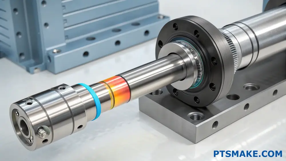
Temperature significantly affects interference fit performance by altering the dimensions of mating components. When heated, materials expand, and when cooled, they contract. This thermal behavior directly impacts the interference pressure and holding force between the assembled parts.
Understanding the Basics of Thermal Effects
Thermal Expansion and Contraction
When dealing with interference fits, understanding thermal effects is crucial. Materials respond differently to temperature changes based on their coefficient of thermal expansion12. At PTSMAKE, we frequently work with various materials, and I’ve observed how temperature variations can significantly impact fit tolerances.
The basic relationship can be expressed through this simplified formula:
∆L = L₀ × α × ∆T
Where:
- ∆L = Change in length
- L₀ = Original length
- α = Coefficient of thermal expansion
- ∆T = Temperature change
Material-Specific Considerations
Different materials exhibit varying thermal behaviors, which affects their interference fit characteristics:
| Material | Thermal Expansion Coefficient (×10⁻⁶/°C) | Temperature Sensitivity |
|---|---|---|
| Steel | 11-13 | Moderate |
| Aluminum | 22-24 | High |
| Brass | 18-20 | High |
| Titanium | 8.6 | Low |
Impact on Assembly and Performance
Assembly Considerations
Temperature differences during assembly can either facilitate or complicate the fitting process. For instance, when assembling a steel shaft into an aluminum housing, heating the housing or cooling the shaft can temporarily alter their dimensions, making assembly easier.
Performance Implications
The performance of an interference fit under varying operating temperatures depends on several factors:
Operating Temperature Range
- Normal operating conditions
- Extreme temperature exposure
- Temperature cycling effects
Material Combination Effects
- Similar material combinations
- Dissimilar material combinations
- Interface pressure variations
Design Strategies for Temperature Compensation
Calculation Methods
To account for thermal effects in interference fit designs, consider these factors:
- Maximum Operating Temperature
- Minimum Operating Temperature
- Assembly Temperature
- Material Properties of Both Components
Design Guidelines
For optimal interference fit performance across temperature ranges:
Select materials with compatible thermal expansion coefficients
Calculate interference allowances considering:
- Room temperature dimensions
- Operating temperature range
- Required interference at extreme temperatures
Consider safety factors for:
- Thermal cycling
- Stress relaxation
- Material property variations
Quality Control and Testing
Temperature Monitoring
At PTSMAKE, we implement strict temperature monitoring during both manufacturing and assembly:
- Pre-assembly temperature verification
- Assembly environment temperature control
- Post-assembly temperature stabilization
Validation Methods
To ensure reliable interference fit performance:
- Thermal cycling tests
- Pull-out force measurements at various temperatures
- Dimensional stability monitoring
Practical Applications and Case Studies
Industrial Applications
Common interference fit applications affected by temperature:
- Bearing installations
- Gear assemblies
- Shaft couplings
- Wheel hubs
Problem Prevention Strategies
Based on our experience at PTSMAKE, we recommend:
- Precise temperature control during assembly
- Proper material selection and treatment
- Regular maintenance and inspection protocols
- Documentation of assembly conditions
Future Trends and Innovations
Advanced Materials
New materials are being developed with:
- Better thermal stability
- Improved dimensional control
- Enhanced performance characteristics
Smart Manufacturing Solutions
Modern manufacturing approaches include:
- Real-time temperature monitoring
- Automated assembly systems
- Predictive maintenance capabilities
This comprehensive understanding of temperature effects on interference fits helps engineers design more reliable and efficient assemblies. By considering thermal behavior during design, manufacturing, and assembly phases, we can create more robust and dependable mechanical connections.
Click to learn more about precise measurements and tolerance calculations for perfect fits. ↩
Click to learn more about pressure distribution in interference fits and optimize your designs. ↩
Click to learn more about elastic behavior in interference fits and optimize your design decisions. ↩
Click to learn advanced engineering principles about radial pressure calculations and optimization. ↩
Click to learn advanced GD&T techniques for optimal fit selection. ↩
Click to learn about the crucial role of interference fits in precision engineering. ↩
Click to learn more about GD&T principles and their practical applications in manufacturing. ↩
Click to learn more about calculating precise interference tolerances for your specific application. ↩
Click here to learn more about material deformation principles and how they affect your designs. ↩
Click to learn more about thermal expansion in interference fit applications and its critical role in assembly success. ↩
Click to learn more about stress analysis in interference fits ↩
Click to learn more about thermal expansion coefficients and their practical applications in engineering design. ↩