Have you ever received flanges that just don’t align properly with your equipment? It’s frustrating when poor machining leads to leaks, equipment failures, and costly downtime. I’ve seen how these issues can bring entire production lines to a halt.
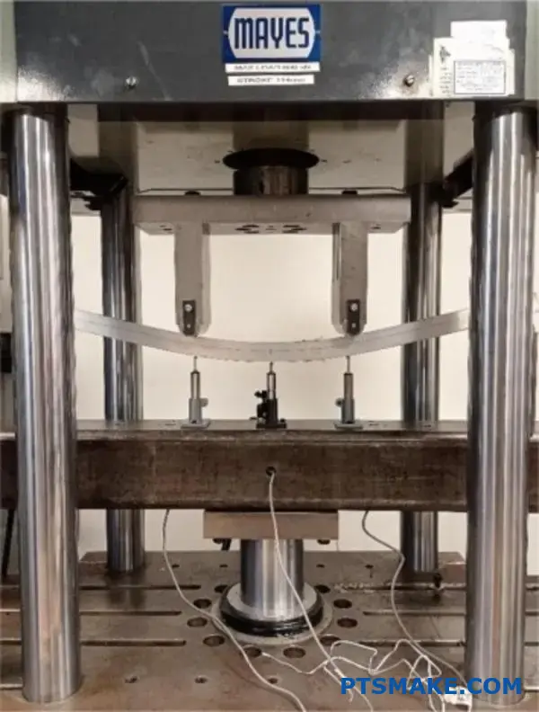
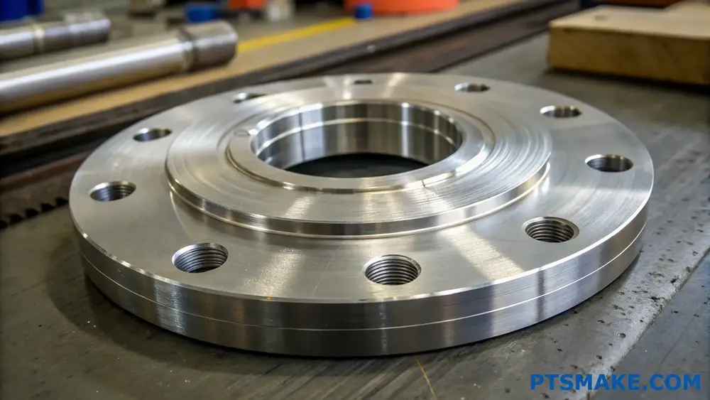
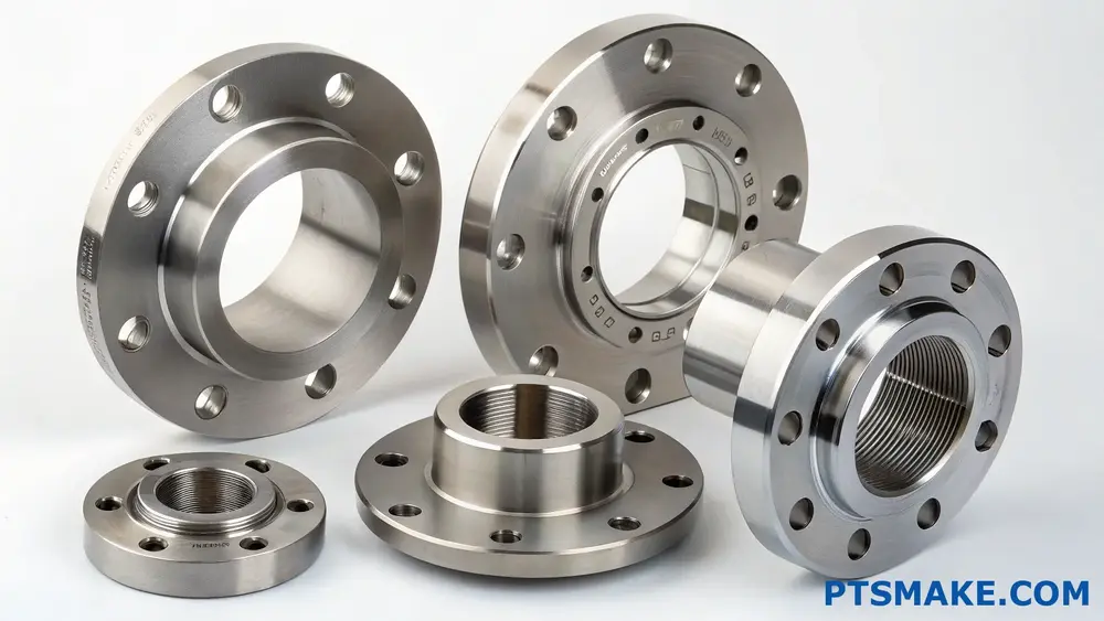
Flange machining is a precision manufacturing process that shapes and finishes metal flanges to exact specifications. This process includes facing, boring, drilling, and threading operations to create reliable connections between pipes, vessels, and mechanical systems.
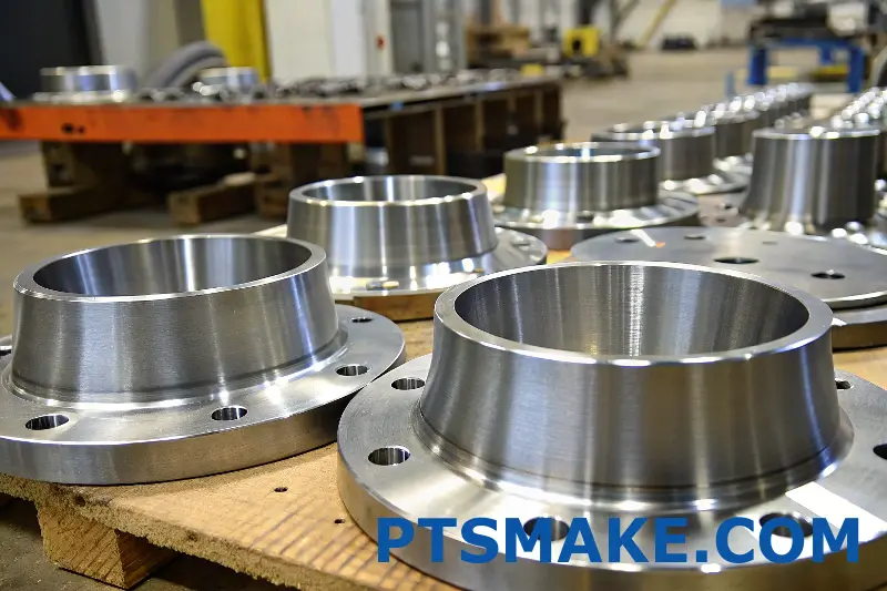
At PTSMAKE, I often explain to our clients that proper flange machining is more than just cutting metal – it’s about ensuring perfect sealing surfaces and alignment. Let me share the key aspects of flange machining and why precision matters in every step of the process. The quality of your flange connections directly impacts your system’s performance and longevity.
What Are The 3 Most Common Flange Types?
Have you ever faced the challenge of selecting the right flange for your project? It’s a common dilemma that can lead to costly mistakes, production delays, and potential safety risks if not addressed properly. The overwhelming variety of flange types often leaves engineers scratching their heads.
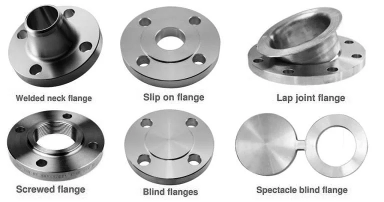
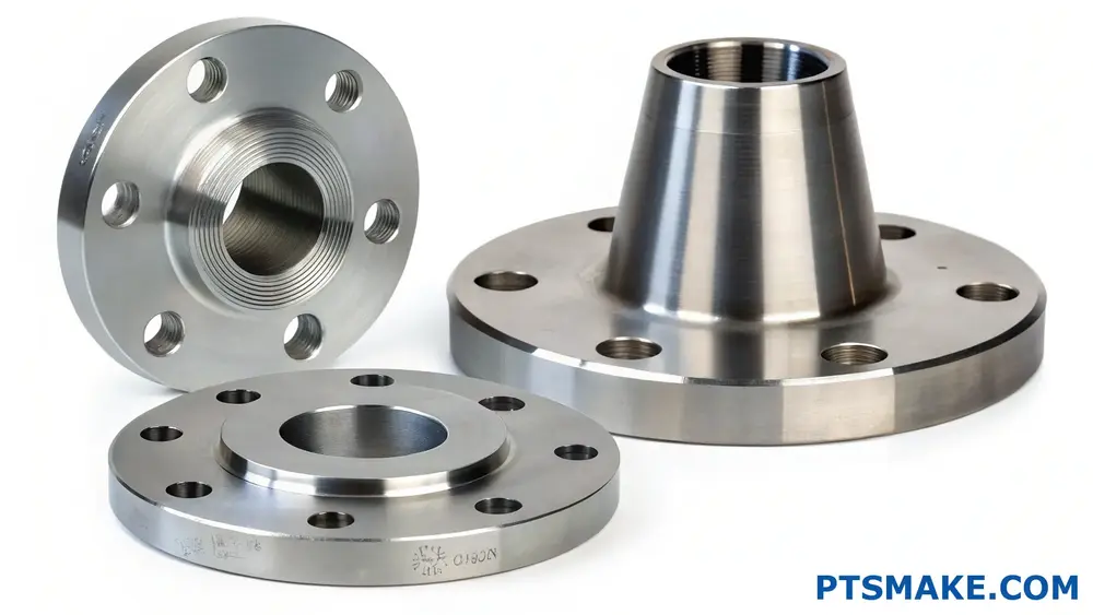
The three most common flange types are Weld Neck flanges, Slip-On flanges, and Blind flanges. Each type serves specific purposes in different applications, offering unique advantages in terms of pressure resistance, installation flexibility, and cost-effectiveness.
Understanding Weld Neck Flanges
Weld Neck flanges are the go-to choice for high-pressure and high-temperature applications. Their distinctive feature is the long tapered hub that transitions smoothly into the pipe wall. This design provides exceptional strength and creates uniform stress distribution throughout the joint.
Key Features of Weld Neck Flanges
- Superior stress distribution
- Excellent fatigue resistance
- Perfect for high-pressure systems
- Reduced maintenance requirements
The stress concentration factor1 in Weld Neck flanges is significantly lower compared to other types, making them ideal for critical applications in petrochemical plants and power generation facilities.
Exploring Slip-On Flanges
At PTSMAKE, we frequently machine Slip-On flanges due to their versatility and cost-effectiveness. These flanges slide over the pipe and are welded both internally and externally, providing a secure connection.
Benefits of Slip-On Flanges
- Lower material costs
- Easier installation
- More forgiving alignment
- Reduced welding expertise requirements
Here’s a comparison of installation time and costs:
| Flange Type | Installation Time | Relative Cost | Skill Level Required |
|---|---|---|---|
| Slip-On | 2-3 hours | Low | Moderate |
| Weld Neck | 4-5 hours | High | High |
The Versatility of Blind Flanges
Blind flanges serve as solid covers to seal pipe ends, vessels, or testing points. They’re essential components in maintenance operations and system modifications.
Applications of Blind Flanges
- System isolation during maintenance
- Pressure testing
- Future expansion points
- Emergency shutoff points
Material Selection and Manufacturing Considerations
The choice of material significantly impacts flange performance. Common materials include:
Standard Materials for Flanges
| Material | Pressure Rating | Temperature Range | Corrosion Resistance |
|---|---|---|---|
| Carbon Steel | Up to 300 PSI | -20° to 800°F | Moderate |
| Stainless Steel | Up to 1000 PSI | -325° to 1500°F | Excellent |
| Alloy Steel | Up to 2500 PSI | -50° to 1200°F | Very Good |
Quality Control in Flange Manufacturing
At PTSMAKE, our quality control process for flange machining involves:
- Material certification verification
- Dimensional inspection
- Surface finish measurement
- Pressure testing when required
- Non-destructive testing for critical applications
Industry Standards and Specifications
Flanges must comply with various international standards:
- ASME B16.5 for pipe flanges
- API 6A for wellhead equipment
- DIN standards for European applications
- JIS for Japanese industrial standards
Cost Considerations and ROI
When selecting flanges, consider these cost factors:
- Initial material cost
- Installation labor
- Maintenance requirements
- Expected service life
- Potential downtime costs
Installation Best Practices
Proper installation is crucial for flange performance:
- Clean mating surfaces thoroughly
- Use appropriate gaskets
- Follow bolt tightening sequences
- Apply correct torque values
- Perform leak testing
Safety Considerations
Safety is paramount in flange selection and installation:
- Always verify pressure ratings
- Consider environmental factors
- Use appropriate personal protective equipment
- Follow proper installation procedures
- Maintain regular inspection schedules
Future Trends in Flange Design
The flange industry is evolving with:
- Advanced materials development
- Smart monitoring systems
- Improved sealing technologies
- Automated manufacturing processes
- Enhanced coating technologies
Maintenance and Inspection
Regular maintenance ensures optimal flange performance:
- Visual inspection for corrosion
- Bolt tension checking
- Gasket condition assessment
- Leak detection
- Documentation of findings
Through my experience at PTSMAKE, I’ve found that proper flange selection and maintenance significantly reduce system failures and maintenance costs. Understanding these three common flange types helps engineers make informed decisions for their specific applications.
What Is The Purpose Of A Flange?
Have you ever wondered why some pipe connections look like flat discs with holes around them? Or maybe you’ve encountered leaks at pipe joints despite seemingly tight connections? These common issues in industrial settings can lead to costly downtime and safety hazards.
A flange is a protruding rim or edge used to connect pipes, valves, pumps, and other equipment in industrial systems. Its primary purpose is to create strong, reliable, and leak-proof connections while allowing for easy assembly and disassembly during maintenance or modifications.
Understanding Different Types of Flanges
The world of flanges is diverse, with each type serving specific applications. At PTSMAKE, we regularly machine various flange types to meet different industry requirements. Here are the main categories:
Weld Neck Flanges
These flanges feature a long tapered hub that’s welded directly to the pipe. The gradual transition from flange to pipe makes them ideal for high-pressure and high-stress applications. The stress distribution2 across the welded joint enhances the overall system reliability.
Slip-On Flanges
More economical than weld neck flanges, slip-on flanges slide over the pipe and are welded both internally and externally. While they’re easier to align during installation, they generally have lower pressure ratings.
Blind Flanges
These solid disc-shaped flanges serve as caps to close off piping systems. They’re essential for:
- System isolation during maintenance
- Pressure testing
- Future expansion points
- Emergency shutoffs
Critical Dimensions and Specifications
When designing or selecting flanges, several key dimensions must be considered:
| Dimension | Description | Importance |
|---|---|---|
| Bore Size | Internal diameter | Determines flow capacity |
| Outside Diameter | Total flange width | Affects installation space |
| Bolt Circle | Diameter of bolt pattern | Critical for proper alignment |
| Face Type | Surface finish style | Impacts sealing effectiveness |
Material Selection Considerations
Material choice significantly impacts flange performance and longevity. Common materials include:
Carbon Steel Flanges
- Most economical option
- Suitable for moderate temperatures
- Good for general industrial applications
- Requires proper coating for corrosion resistance
Stainless Steel Flanges
- Superior corrosion resistance
- Ideal for food and pharmaceutical industries
- Higher cost but longer lifespan
- Better performance in extreme temperatures
Special Alloy Flanges
- Used in aggressive environments
- Custom-engineered for specific applications
- Higher material and machining costs
- Extended service life in harsh conditions
Flange Face Types and Their Applications
The face type of a flange directly affects its sealing capability:
Raised Face
The most common type in industrial applications, featuring a slightly elevated surface around the bore. This design:
- Concentrates gasket stress
- Improves sealing effectiveness
- Reduces required bolt loads
- Simplifies maintenance procedures
Flat Face
Used primarily with cast iron flanges and where alignment is critical:
- Prevents flange distortion
- Ideal for brittle materials
- Requires full-face gaskets
- Provides uniform compression
Ring Type Joint
Designed for high-pressure applications:
- Uses metallic ring gaskets
- Provides excellent sealing
- Requires precise machining
- Common in oil and gas industries
Quality Control in Flange Manufacturing
At PTSMAKE, we implement rigorous quality control measures:
Material Verification
- Chemical composition testing
- Physical properties validation
- Heat treatment certification
- Material traceability
Dimensional Inspection
- Advanced CMM measurements
- Surface finish verification
- Roundness and flatness checks
- Bolt hole alignment validation
Non-Destructive Testing
- Magnetic particle inspection
- Ultrasonic testing
- Dye penetrant examination
- Radiographic inspection when required
Installation and Maintenance Best Practices
Proper installation ensures optimal flange performance:
Alignment Requirements
- Use alignment pins when necessary
- Check parallel alignment of mating surfaces
- Verify proper spacing
- Ensure even gasket compression
Torque Specifications
- Follow manufacturer’s torque values
- Use calibrated torque wrenches
- Implement proper bolt tightening sequence
- Document torque values for reference
Regular Inspection Points
- Check for visible damage
- Monitor for leaks
- Inspect bolt tightness
- Evaluate gasket condition
What Is Flange Technique?
Have you ever struggled with getting precise, uniform flanges in your manufacturing projects? The frustration of dealing with irregular surfaces, misaligned holes, or poor sealing performance can turn what should be a straightforward process into a manufacturing nightmare.
Flange technique refers to the specialized manufacturing process of creating and machining flanges – the raised edges or rims used to strengthen objects and create strong connections between components. This process combines precision machining with specific material considerations to ensure optimal performance and reliability.
Understanding Flange Types and Applications
Flanges come in various types, each designed for specific applications. The selection of the right flange type is crucial for ensuring optimal performance in different operating conditions. Here’s a comprehensive breakdown of common flange types:
Common Flange Types
| Flange Type | Primary Use | Key Features |
|---|---|---|
| Weld Neck | High-pressure systems | Long tapered hub, excellent stress distribution |
| Slip-On | Low-pressure applications | Easy installation, cost-effective |
| Socket Weld | Small diameter pipes | Enhanced strength, good for high pressure |
| Blind | System termination | Complete closure, removable access |
| Lap Joint | Frequent maintenance | Easy alignment, rotation capability |
Critical Aspects of Flange Manufacturing
The manufacturing of flanges requires careful attention to several critical factors. The material crystallography3 plays a vital role in determining the flange’s performance and longevity. At PTSMAKE, we’ve developed specialized techniques to ensure optimal material selection and processing.
Material Selection Considerations
The choice of material significantly impacts flange performance. Common materials include:
- Carbon Steel: Excellent for general applications
- Stainless Steel: Ideal for corrosive environments
- Alloy Steel: Perfect for high-temperature applications
- Nickel Alloys: Suitable for extreme conditions
Precision Machining Requirements
Achieving precise flange specifications requires advanced machining techniques. The key aspects include:
Surface Finish Requirements
- Face Roughness: Must meet specific Ra values
- Flatness Tolerance: Typically within 0.002 inches
- Groove Depth: Precise measurements for gasket seating
Quality Control Measures
Quality control is essential in flange manufacturing. We implement:
Dimensional Inspection
| Measurement Point | Tolerance Range | Inspection Method |
|---|---|---|
| Bolt Hole Size | ±0.015 inches | Digital gauges |
| Face Flatness | 0.002 inches max | Surface plates |
| Outside Diameter | ±0.031 inches | Micrometers |
Testing Procedures
- Hydrostatic Testing: Ensures pressure integrity
- Ultrasonic Testing: Detects internal defects
- Magnetic Particle Testing: Identifies surface flaws
Best Practices for Flange Installation
Proper installation is crucial for flange performance. Key considerations include:
- Bolt Tightening Sequence: Follow specific patterns
- Torque Values: Adhere to manufacturer specifications
- Gasket Selection: Match with flange type and application
Common Challenges and Solutions
Alignment Issues
- Use of alignment pins
- Implementation of laser alignment tools
- Proper support during installation
Surface Defects
- Regular inspection protocols
- Proper storage and handling
- Surface preparation techniques
Performance Optimization
To maximize flange performance:
Regular Maintenance
- Scheduled inspections
- Cleaning procedures
- Gasket replacement intervals
Environmental Considerations
- Temperature fluctuations
- Chemical exposure
- Mechanical stress
Documentation
- Installation records
- Maintenance history
- Performance tracking
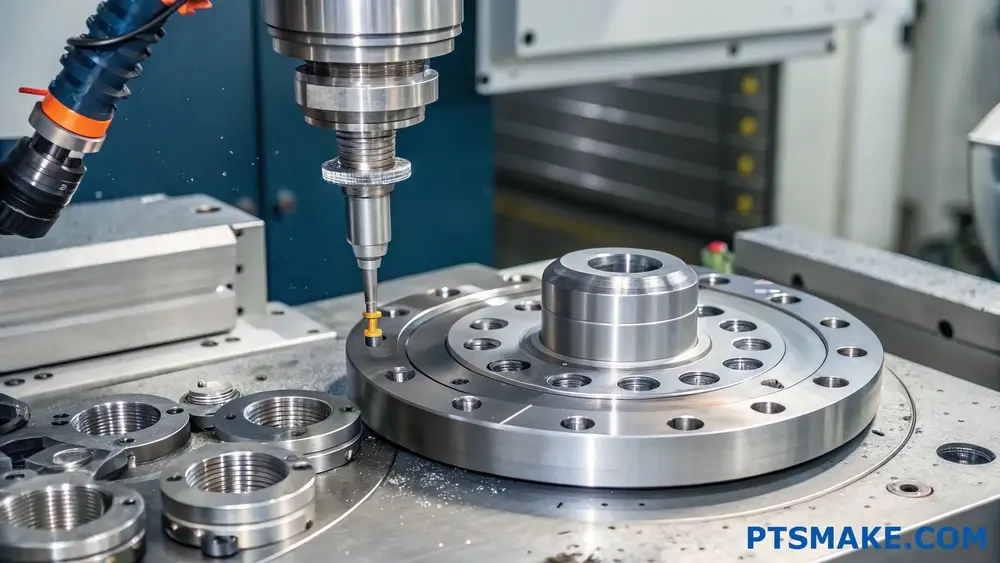
At PTSMAKE, we utilize advanced CNC machining centers and strict quality control processes to ensure each flange meets exact specifications. Our expertise in precision manufacturing allows us to handle complex flange requirements while maintaining tight tolerances and superior surface finishes.
The success of flange applications depends heavily on proper technique implementation. By following these guidelines and working with experienced manufacturers, you can ensure reliable and efficient flange performance in your applications.
What Is The Difference Between Welded And Flange?
Have you ever found yourself struggling to choose between welded and flange connections for your project? The decision can feel overwhelming, especially when considering factors like cost, maintenance, and long-term reliability. The wrong choice could lead to costly repairs or system failures.
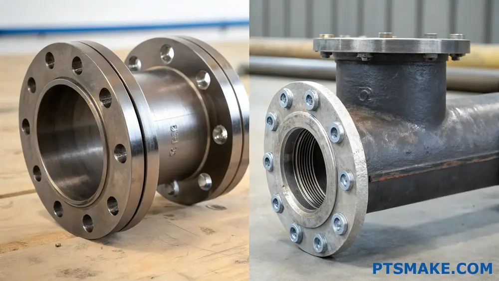
The main difference between welded and flange connections lies in their assembly method. Welded connections are permanent joints created through fusion, while flanges are mechanical connections that can be disassembled using bolts and gaskets, offering easier maintenance but potentially higher initial costs.
Understanding Welded Connections
Key Characteristics of Welded Joints
Welded connections create permanent bonds between metal components through a fusion process. At PTSMAKE, we’ve mastered various welding techniques to ensure optimal joint strength. The process involves heating materials to their melting point and allowing them to cool and solidify as one piece.
The metallurgical bonding4 process creates several advantages:
- Superior joint strength
- Excellent leak resistance
- Lower initial cost
- Reduced weight
- Streamlined appearance
Common Applications
Welded connections excel in:
- High-pressure systems
- Structural applications
- Permanent installations
- Weight-critical components
- Areas with space constraints
Understanding Flange Connections
Basic Components
A typical flange connection consists of:
| Component | Function | Material Options |
|---|---|---|
| Flange Face | Provides sealing surface | Steel, Stainless Steel |
| Gasket | Creates seal between faces | Various elastomers, metals |
| Bolts/Nuts | Secures connection | High-strength steel |
| Washers | Distributes clamping force | Hardened steel |
Types of Flanges
The most common flange types include:
- Slip-on Flanges
- Weld Neck Flanges
- Socket Weld Flanges
- Lap Joint Flanges
- Threaded Flanges
Comparative Analysis
Installation Considerations
| Aspect | Welded Connections | Flange Connections |
|---|---|---|
| Skill Required | High (certified welders) | Moderate |
| Equipment Needed | Welding machines, safety gear | Basic tools |
| Installation Time | Longer | Shorter |
| Quality Control | X-ray, ultrasonic testing | Visual inspection |
Maintenance Factors
| Factor | Welded | Flange |
|---|---|---|
| Disassembly | Requires cutting | Easy removal |
| Inspection | Limited access | Full access |
| Repair Cost | Higher | Lower |
| Service Life | Usually longer | Depends on maintenance |
Cost Implications
Initial Costs
Welded connections typically have lower initial costs due to:
- Fewer components required
- Less material usage
- Simpler inventory management
Flange connections involve:
- Purchase of flanges, gaskets, and fasteners
- Higher material costs
- More complex inventory
Long-term Considerations
When evaluating total cost of ownership:
Welded connections:
- Minimal maintenance costs
- Higher repair/replacement expenses
- Limited flexibility for modifications
Flange connections:
- Regular gasket replacement
- Higher maintenance frequency
- Lower repair costs
- Greater modification flexibility
Industry-Specific Applications
Chemical Processing
In chemical processing:
- Welded connections: Preferred for hazardous materials
- Flange connections: Used for equipment requiring frequent maintenance
Oil and Gas
The oil and gas sector uses:
- Welded connections: High-pressure transmission lines
- Flange connections: Valve connections, equipment interfaces
Water Treatment
Water treatment facilities employ:
- Welded connections: Main distribution lines
- Flange connections: Pump connections, filter assemblies
Design Considerations
Load Bearing
Welded connections provide superior strength in:
- Structural applications
- High-stress environments
- Dynamic loading conditions
Flange connections require:
- Proper bolt torque
- Regular monitoring
- Consideration of thermal expansion
Space Requirements
Space considerations include:
- Welded connections: Minimal space needed
- Flange connections: Additional clearance for assembly/disassembly
Making the Right Choice
Consider these factors when choosing:
- Application requirements
- Maintenance needs
- Installation environment
- Budget constraints
- Safety regulations
At PTSMAKE, we help clients evaluate these factors through our comprehensive engineering support services, ensuring the most suitable connection type for each application.
What Is The Difference Between A Raised Face And A Flange Face?
Have you ever found yourself staring at flange specifications, wondering why some mention "raised face" while others just say "flange face"? This confusion can lead to costly mistakes in manufacturing and potentially dangerous situations in high-pressure applications.
A raised face flange has an elevated sealing surface that extends above the bolt face, while a flat face flange has a sealing surface that’s level with the bolt face. Raised face flanges are common in high-pressure applications, while flat face flanges are typically used in low-pressure systems.
Understanding Flange Face Types
When it comes to flange faces, the design choice significantly impacts the sealing effectiveness and safety of the connection. At PTSMAKE, we regularly machine both types of flanges, and I’ve observed that understanding their differences is crucial for proper application.
Raised Face Flange Characteristics
The raised face flange features a distinctive serrated surface5 that extends above the flange’s bolt face. This design creates several advantages:
- Enhanced Sealing Capability
- Better Gasket Retention
- Higher Pressure Handling
- Improved Leak Prevention
The height of the raised portion typically ranges from:
| Flange Class | Raised Face Height (mm) | Common Applications |
|---|---|---|
| 150# – 300# | 1.6 | Process piping |
| 400# – 600# | 6.4 | Chemical industry |
| 900# – 2500# | 7.1 | High-pressure systems |
Flat Face Flange Features
Flat face flanges maintain a continuous, level surface across the entire flange face. These are particularly suitable for:
- Low-pressure applications
- Systems with brittle piping materials
- Cast iron connections
- Glass-lined equipment
Sealing Mechanism Differences
The sealing mechanism varies significantly between these two types:
| Feature | Raised Face | Flat Face |
|---|---|---|
| Contact Area | Concentrated | Full surface |
| Gasket Type | Compressed | Full-face |
| Bolt Load | Higher | Lower |
| Pressure Rating | Higher | Lower |
Material Considerations
The choice of flange face type often depends on the material being used:
Compatible Materials for Raised Face Flanges:
- Stainless Steel
- Carbon Steel
- Alloy Steel
- Nickel Alloys
Suitable Materials for Flat Face Flanges:
- Cast Iron
- PVC
- FRP (Fiber Reinforced Plastic)
- Glass-lined Steel
Installation and Maintenance Aspects
The installation process differs between these flange types:
Raised Face Installation:
- Requires specific torque patterns
- Needs careful gasket alignment
- Demands proper bolt tensioning
- Benefits from sequential tightening
Flat Face Installation:
- Simpler alignment process
- More forgiving with gasket placement
- Lower risk of gasket damage
- Requires less specialized knowledge
Industry Applications
Different industries favor specific flange face types based on their requirements:
Raised Face Applications:
- Oil and gas processing
- Chemical manufacturing
- High-temperature systems
- Steam distribution networks
Flat Face Applications:
- Water treatment facilities
- Low-pressure chemical transfer
- HVAC systems
- Food processing equipment
Cost Implications
The manufacturing costs between these types vary significantly:
| Cost Factor | Raised Face | Flat Face |
|---|---|---|
| Machining Time | Higher | Lower |
| Material Waste | More | Less |
| Tool Wear | Higher | Lower |
| Quality Control | More Complex | Simpler |
At PTSMAKE, we’ve optimized our manufacturing processes to maintain cost-effectiveness while ensuring precise specifications for both types. Our advanced CNC machining centers allow us to produce these flanges with exceptional accuracy and surface finish.
Safety Considerations
When selecting between raised face and flat face flanges, safety should be a primary concern:
Raised Face Safety Features:
- Better containment of high pressures
- Reduced risk of gasket blowout
- Enhanced leak detection capability
- Superior joint integrity
Flat Face Safety Aspects:
- Lower stress on brittle materials
- More uniform load distribution
- Reduced risk of flange warping
- Better suited for frequent assembly/disassembly
What Is The Most Common Type Of Flange?
Have you ever found yourself puzzled when selecting flanges for your project? The sheer variety of flange types can be overwhelming, and choosing the wrong one could lead to costly system failures or safety hazards. Let’s clear up this confusion once and for all.
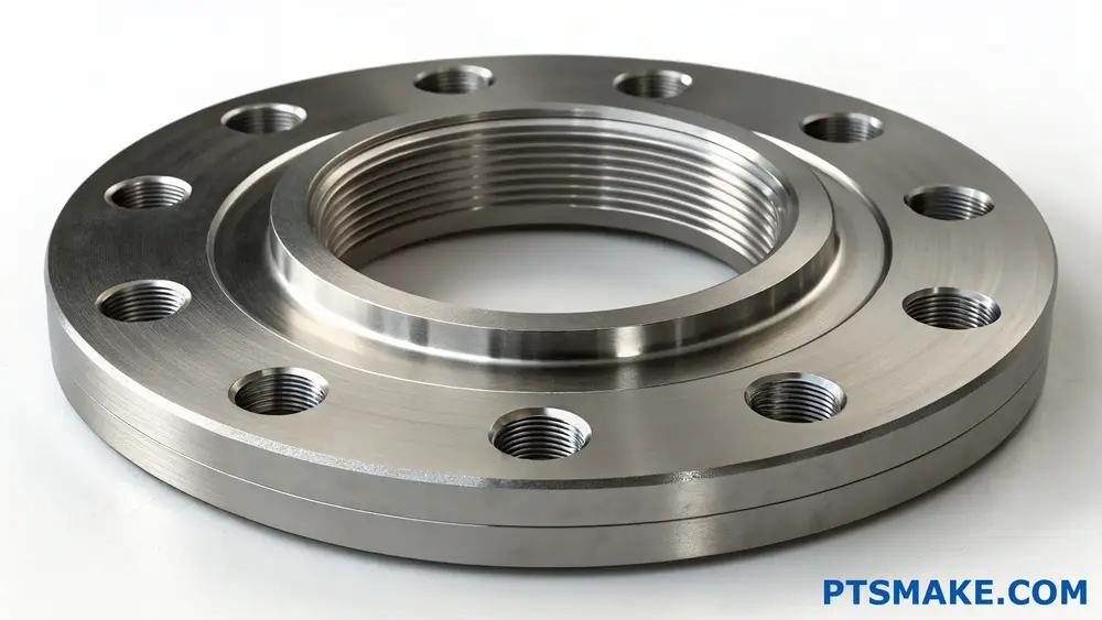
The most common type of flange is the slip-on flange, widely used in piping systems across various industries. It features a simple design that slides over the pipe and gets welded both internally and externally, making it cost-effective and easier to install compared to other flange types.
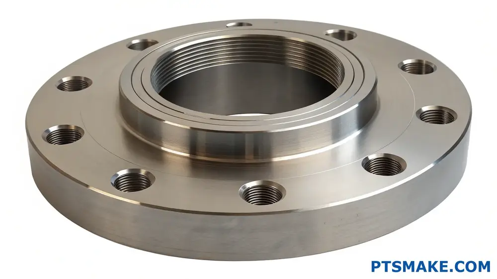
Understanding Slip-on Flanges
Slip-on flanges have gained their popularity due to their versatility and straightforward installation process. These flanges feature a bore slightly larger than the outside diameter of the pipe they’re meant to fit. The radial clearance6 between the pipe and flange typically ranges from 1/8 inch to 3/16 inch, allowing for easy assembly while maintaining structural integrity.
Key Features of Slip-on Flanges
- Lower material costs compared to weld neck flanges
- Simpler installation process
- More forgiving of minor pipe misalignment
- Requires both internal and external welding
- Available in various pressure ratings and sizes
Common Applications and Industries
Slip-on flanges find extensive use across multiple sectors:
Industrial Processing
- Chemical processing plants
- Food and beverage manufacturing
- Pharmaceutical facilities
- Water treatment plants
Oil and Gas
- Pipeline systems
- Storage facilities
- Refineries
- Distribution networks
Material Selection and Standards
The choice of material for slip-on flanges depends on various factors:
| Material | Common Applications | Corrosion Resistance | Cost Factor |
|---|---|---|---|
| Carbon Steel | General purpose | Moderate | Low |
| Stainless Steel | Chemical processing | High | Medium |
| Alloy Steel | High-temperature | Very High | High |
| Bronze | Marine applications | High | Medium-High |
Installation Considerations
Proper installation is crucial for slip-on flange performance. At PTSMAKE, we’ve developed a comprehensive approach to ensure optimal installation:
Preparation Steps
- Clean pipe ends thoroughly
- Check pipe alignment
- Verify flange dimensions
- Ensure proper clearance
Welding Requirements
- Internal weld to prevent leakage
- External weld for structural strength
- Proper heat treatment when required
- Post-weld inspection
Advantages Over Other Flange Types
When compared to other common flange types, slip-on flanges offer several benefits:
Cost Benefits
- Lower initial material cost
- Reduced machining requirements
- More economical shipping due to lighter weight
- Easier inventory management
Installation Benefits
- More forgiving of field conditions
- Easier to position and adjust
- Simpler welding process
- Reduced installation time
Maintenance and Inspection
Regular maintenance ensures long-term reliability:
Inspection Points
- Check for corrosion around welds
- Monitor bolt tension
- Inspect gasket condition
- Verify alignment stability
Design Considerations
When selecting slip-on flanges, several factors need consideration:
Operating Parameters
- System pressure requirements
- Temperature ranges
- Chemical compatibility
- Mechanical stress factors
Dimensional Requirements
- Pipe size compatibility
- Bolt circle diameter
- Face-to-face dimensions
- Gasket surface finish
Quality Control Measures
At PTSMAKE, we implement strict quality control procedures:
Manufacturing Controls
- Material certification verification
- Dimensional inspection
- Surface finish measurement
- Pressure testing when required
Documentation Requirements
- Material test reports
- Dimensional reports
- Welding procedure specifications
- Inspection records
Industry Standards and Compliance
Slip-on flanges must meet various standards:
| Standard | Region | Application |
|---|---|---|
| ASME B16.5 | Global | General Purpose |
| EN 1092-1 | Europe | Industrial |
| JIS B2220 | Japan | Process Industry |
| AS 2129 | Australia | Industrial |
Cost Analysis
Understanding the total cost of ownership helps in making informed decisions:
Direct Costs
- Material costs
- Manufacturing expenses
- Installation labor
- Welding requirements
Indirect Costs
- Maintenance requirements
- Potential downtime
- Replacement frequency
- Installation equipment needs
Through my experience at PTSMAKE, I’ve found that slip-on flanges often provide the best balance of cost, performance, and ease of installation for many applications. While other flange types might be better suited for specific high-pressure or critical applications, slip-on flanges remain the most common and versatile choice for general industrial use.
What Are The Standard Types Of Flanges?
Have you ever faced the frustration of selecting the wrong flange type for your project? It’s a common challenge that can lead to costly delays, safety concerns, and compatibility issues. The consequences of making incorrect flange selections can be severe.
A flange is a protruding rim or edge used to attach pipes, valves, pumps, and other equipment in industrial applications. Standard flange types include slip-on, weld neck, socket weld, lap joint, threaded, and blind flanges, each designed for specific pressure ratings and applications.
Common Types of Standard Flanges
Weld Neck Flanges
Weld neck flanges are among the most widely used types in high-pressure and high-temperature applications. Their distinctive feature is the long tapered hub that provides reinforcement and helps distribute stress. When manufacturing these flanges at PTSMAKE, we ensure the stress concentration7 is minimized through precise machining of the hub transition area.
Slip-On Flanges
These flanges are popular due to their cost-effectiveness and ease of installation. They slide over the pipe and are welded both internally and externally. While working with clients, I often recommend slip-on flanges for low to moderate pressure applications where cost is a significant factor.
Socket Weld Flanges
Socket weld flanges are excellent choices for small-diameter piping systems. They provide a socket that the pipe fits into, creating a strong joint when welded. These flanges are particularly useful in applications where radiography testing isn’t required.
Material Selection and Standards
The choice of flange material is crucial for longevity and safety. Here’s a comparison of common materials:
| Material | Pressure Rating (PSI) | Temperature Range (°F) | Corrosion Resistance |
|---|---|---|---|
| Carbon Steel | Up to 2500 | -20 to 800 | Moderate |
| Stainless Steel | Up to 3000 | -325 to 1500 | Excellent |
| Alloy Steel | Up to 4500 | -50 to 1200 | Very Good |
| Bronze | Up to 1000 | -65 to 550 | Good |
Pressure Class Ratings
Understanding pressure ratings is essential for proper flange selection. Common pressure classes include:
Class 150
Suitable for most standard industrial applications with working pressures up to 285 PSI, depending on temperature and material.
Class 300
Designed for medium-pressure applications, capable of handling pressures up to 740 PSI under optimal conditions.
Class 600 and Higher
Used in high-pressure systems where safety and reliability are paramount.
Surface Finish Requirements
The surface finish of a flange is critical for proper sealing. At PTSMAKE, we maintain strict adherence to industry standards:
- Ra 125-250 microinches: Standard finish for most applications
- Ra 32-63 microinches: For critical sealing requirements
- Ra below 32 microinches: For specialized high-purity applications
Installation Considerations
Proper installation is crucial for flange performance. Key factors include:
Bolt Pattern Alignment
- Ensure correct bolt hole alignment
- Use appropriate torque sequences
- Maintain even compression on gaskets
Gasket Selection
The right gasket material and type significantly impact flange performance:
| Gasket Type | Application | Temperature Range | Chemical Resistance |
|---|---|---|---|
| Compressed Fiber | General Use | Up to 750°F | Good |
| PTFE | Chemical Processing | Up to 500°F | Excellent |
| Spiral Wound | High Pressure | Up to 1800°F | Very Good |
| Metal | Extreme Conditions | Up to 2000°F | Excellent |
Quality Control Measures
At PTSMAKE, we implement comprehensive quality control procedures:
- Dimensional inspection using precision measuring equipment
- Material certification verification
- Surface finish testing
- Pressure testing when required
Industry Applications
Different industries require specific flange types:
Oil and Gas
- High-pressure weld neck flanges
- Corrosion-resistant materials
- Regular maintenance schedules
Chemical Processing
- Chemical-resistant materials
- Special surface finish requirements
- Specific gasket compatibility
Water Treatment
- Lower pressure ratings
- Cost-effective solutions
- Corrosion resistance priority
Maintenance and Inspection
Regular maintenance ensures long-term reliability:
- Visual inspection for corrosion
- Bolt torque verification
- Gasket condition assessment
- Surface damage evaluation
Future Trends
The flange industry continues to evolve with:
- Advanced materials development
- Improved sealing technologies
- Enhanced manufacturing processes
- Digital monitoring capabilities
How To Ensure Precision In Flange Machining For Aerospace Applications?
Have you ever faced the frustration of aerospace flange components failing quality inspections despite your best efforts? The stakes are incredibly high in aerospace manufacturing, where even microscopic deviations can lead to catastrophic failures and costly recalls.
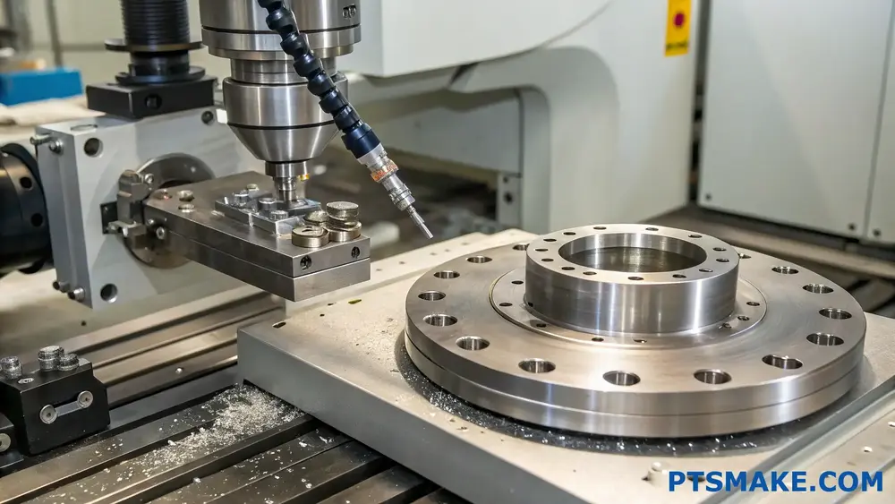
Ensuring precision in aerospace flange machining requires a comprehensive approach combining advanced machining techniques, rigorous quality control processes, and specialized tooling. The key focus areas include material selection, temperature control, proper fixture design, and advanced measurement systems.
Understanding Critical Parameters in Aerospace Flange Machining
Material Considerations
The selection of appropriate materials is crucial for aerospace flanges. At PTSMAKE, we primarily work with materials that offer excellent strength-to-weight ratios and corrosion resistance. The most common materials include:
| Material Type | Advantages | Common Applications |
|---|---|---|
| Titanium Alloys | High strength, lightweight | Engine components |
| Inconel | Heat resistance, durability | Exhaust systems |
| Aluminum Alloys | Cost-effective, lightweight | Structural components |
Dimensional Accuracy Requirements
Aerospace flanges require exceptional dimensional stability8 during machining. The typical tolerances we work with are:
| Feature | Tolerance Range |
|---|---|
| Flatness | ±0.002 inches |
| Concentricity | ±0.001 inches |
| Surface Finish | 32-63 µin Ra |
Advanced Machining Strategies
Temperature Control
Temperature management is critical during the machining process. We implement several strategies:
- Climate-controlled machining environment
- Coolant system optimization
- Regular machine calibration
- Temperature monitoring during cutting
Tooling Selection
Proper tool selection significantly impacts machining precision:
- Carbide tools for consistent performance
- Custom-designed fixtures for specific flange configurations
- High-precision collets and tool holders
- Regular tool wear monitoring
Quality Control Measures
Inspection Technologies
We utilize state-of-the-art measurement equipment:
- CMM (Coordinate Measuring Machines)
- Laser scanning systems
- Digital micrometers
- Surface roughness testers
Documentation and Traceability
Maintaining detailed records is essential:
- Material certifications
- Process parameters
- Inspection results
- Tool life tracking
- Machine maintenance records
Process Optimization Techniques
Setup Procedures
Proper setup is crucial for achieving precision:
- Machine warmup protocols
- Tool presetting
- Workpiece alignment verification
- Fixture validation
Cutting Parameters
| Parameter | Consideration |
|---|---|
| Speed | Material-specific recommendations |
| Feed Rate | Surface finish requirements |
| Depth of Cut | Tool life optimization |
| Coolant Flow | Heat dissipation needs |
Common Challenges and Solutions
Vibration Control
Vibration can significantly impact precision. Solutions include:
- Rigid fixture design
- Balanced tooling
- Proper speed and feed selection
- Anti-vibration tool holders
Material Deformation
Managing material stress is crucial:
- Proper material handling
- Staged machining processes
- Stress relief procedures
- Controlled material removal
Industry Best Practices
Program Optimization
CNC programming considerations:
- Tool path optimization
- Constant engagement strategies
- Appropriate entry and exit moves
- Parameter adjustment based on material properties
Maintenance Protocols
Regular maintenance ensures consistent precision:
- Daily machine checks
- Weekly calibration verification
- Monthly alignment checks
- Quarterly preventive maintenance
Future Trends in Aerospace Flange Machining
The industry is evolving with new technologies:
- AI-powered process optimization
- Advanced simulation software
- Real-time monitoring systems
- Automated quality control
At PTSMAKE, we continuously invest in these emerging technologies to maintain our position as a leading precision manufacturing partner for aerospace applications. Our commitment to quality and precision has earned us the trust of major aerospace manufacturers worldwide.
What Materials Are Best Suited For High-Pressure Flange Machining?
Have you ever faced the challenge of selecting the right material for high-pressure flange applications? It’s a critical decision that can mean the difference between consistent performance and catastrophic failure, especially when dealing with pressures that push materials to their limits.
For high-pressure flange machining, the best-suited materials are typically ASTM A105 carbon steel, F316/316L stainless steel, and duplex stainless steel. These materials offer excellent mechanical properties, corrosion resistance, and maintainable machinability while meeting strict industry standards for pressure-bearing applications.
Understanding Material Requirements for High-Pressure Flanges
When selecting materials for high-pressure flange machining, several critical factors must be considered. At PTSMAKE, we prioritize materials that demonstrate exceptional yield strength9 and durability under extreme conditions. The material choice significantly impacts the flange’s performance, safety, and longevity.
Primary Material Options
Carbon Steel (ASTM A105)
Carbon steel remains a popular choice for high-pressure flange applications due to its:
- Excellent strength-to-weight ratio
- Cost-effectiveness
- Good machinability
- High temperature resistance up to 800°F
Stainless Steel (F316/316L)
This material offers superior advantages including:
- Outstanding corrosion resistance
- High ductility
- Excellent weldability
- Enhanced surface finish quality
Duplex Stainless Steel
Notable characteristics include:
- Superior strength compared to standard stainless steel
- Enhanced stress corrosion cracking resistance
- Better fatigue resistance
- Improved pitting resistance
Material Performance Comparison
Let’s examine how these materials compare across key performance metrics:
| Material Type | Tensile Strength (MPa) | Yield Strength (MPa) | Corrosion Resistance | Cost Factor |
|---|---|---|---|---|
| ASTM A105 | 485-655 | 250 | Moderate | Low |
| F316/316L | 515-690 | 205 | Excellent | Medium |
| Duplex SS | 620-795 | 450 | Superior | High |
Material Selection Considerations
Operating Environment
The operating environment plays a crucial role in material selection. In my experience at PTSMAKE, we consider:
- Temperature range
- Pressure conditions
- Chemical exposure
- Environmental factors
Cost-Effectiveness Analysis
When evaluating materials, consider:
- Initial material costs
- Machining expenses
- Maintenance requirements
- Expected service life
Industry-Specific Requirements
Different industries have varying requirements:
Oil and Gas Industry
- High-pressure resistance
- Sulfide stress cracking resistance
- Temperature cycling capability
Chemical Processing
- Chemical compatibility
- Stress corrosion resistance
- Clean ability
Power Generation
- High-temperature stability
- Thermal shock resistance
- Long-term reliability
Machining Considerations
Surface Finish Requirements
The material choice impacts achievable surface finish:
- Carbon steel typically achieves 63-125 RMS
- Stainless steel can achieve 32-63 RMS
- Duplex stainless requires specialized tooling for optimal finish
Tooling Requirements
Different materials demand specific tooling approaches:
- Carbon steel: Standard carbide tooling
- Stainless steel: Cobalt-enhanced tooling
- Duplex: Advanced ceramic or specialized carbide tools
Quality Control Measures
To ensure material integrity:
- Material certification verification
- Non-destructive testing
- Dimensional inspection
- Surface finish validation
Material Optimization Strategies
At PTSMAKE, we employ several strategies to optimize material performance:
Heat Treatment
- Stress relieving for carbon steel
- Solution annealing for stainless steel
- Age hardening when applicable
Surface Treatment
- Protective coatings application
- Surface hardening processes
- Corrosion-resistant treatments
Future Trends in Flange Materials
The industry is evolving with:
- Advanced composite materials
- Higher-grade stainless steel alloys
- Novel surface treatment technologies
- Smart materials with monitoring capabilities
Best Practices for Material Selection
To ensure optimal material selection:
- Define operating parameters clearly
- Consider all environmental factors
- Evaluate cost implications
- Assess maintenance requirements
- Review regulatory requirements
How Does Flange Machining Impact Cost-Efficiency In Automotive Manufacturing?
Have you ever wondered why some automotive manufacturers consistently outperform others in cost management? The challenge often lies in flange machining processes, where even minor inefficiencies can cascade into significant cost overruns and production delays, impacting the entire manufacturing chain.
Flange machining significantly impacts automotive manufacturing costs through precision requirements, material selection, and production efficiency. Optimized flange machining processes can reduce material waste by up to 25% and decrease production time by 30%, directly affecting the bottom line of automotive manufacturing operations.
Understanding the Cost Components of Flange Machining
Material Selection and Its Impact
The choice of materials for flange manufacturing plays a crucial role in cost-efficiency. We’ve found that selecting the right material grade can lead to significant cost savings while maintaining quality standards. The metallurgical composition10 of the material directly affects machining parameters and tool wear rates.
Labor and Time Considerations
Labor costs represent a substantial portion of flange machining expenses. At PTSMAKE, we’ve implemented advanced CNC machining centers that optimize operator efficiency while maintaining precise tolerances. Here’s a breakdown of typical time allocation in flange machining:
| Operation Phase | Time Percentage | Cost Impact |
|---|---|---|
| Setup | 15% | Medium |
| Machining | 45% | High |
| Quality Control | 25% | Medium |
| Material Handling | 15% | Low |
Optimization Strategies for Cost Reduction
Advanced Tooling Solutions
Modern tooling technologies have revolutionized flange machining efficiency. By utilizing high-performance cutting tools and optimized cutting parameters, we’ve achieved remarkable improvements in production rates. The key is finding the right balance between tool life and cutting speed.
Process Automation Benefits
Automation in flange machining offers several advantages:
- Reduced labor costs
- Consistent quality output
- Increased production capacity
- Minimized human error
- Enhanced workplace safety
Quality Control and Its Economic Impact
Inspection Methods and Cost Implications
Quality control procedures, while necessary, can significantly impact overall costs. We’ve developed streamlined inspection protocols that maintain high standards while reducing inspection time:
| Inspection Type | Frequency | Cost Impact |
|---|---|---|
| In-process | Continuous | Medium |
| Post-machining | 100% | High |
| Final Assembly | Sample-based | Low |
Tolerance Management
Maintaining tight tolerances is crucial in automotive flange manufacturing. Our experience shows that investing in precise machining capabilities initially leads to long-term cost savings through:
- Reduced scrap rates
- Fewer assembly issues
- Lower warranty claims
- Improved customer satisfaction
Production Volume Considerations
Batch Size Optimization
The relationship between batch size and cost-efficiency is complex. Large batches can reduce setup costs per unit but may increase inventory carrying costs. We recommend:
- Analyzing order patterns
- Considering storage costs
- Evaluating setup time impacts
- Balancing WIP inventory
Equipment Utilization
Maximizing equipment utilization is crucial for cost-efficiency. At PTSMAKE, we achieve this through:
- Strategic maintenance scheduling
- Multi-machine operation
- Optimized production planning
- Regular performance monitoring
Environmental and Sustainability Factors
Waste Reduction Strategies
Implementing effective waste reduction strategies not only benefits the environment but also improves cost-efficiency:
- Optimized cutting parameters
- Material recovery systems
- Coolant recycling
- Energy-efficient machinery
Energy Efficiency Measures
Energy consumption significantly impacts operational costs. We’ve implemented several measures to reduce energy usage:
- Variable speed drives
- High-efficiency motors
- Smart power management
- LED lighting systems
Future Trends and Cost Implications
Emerging Technologies
New technologies are reshaping flange machining economics:
- AI-powered process optimization
- Digital twin simulation
- Advanced sensor systems
- Predictive maintenance tools
Industry 4.0 Integration
The integration of Industry 4.0 principles offers new opportunities for cost reduction:
- Real-time monitoring
- Data-driven decision making
- Connected manufacturing systems
- Automated quality control
Click to learn how stress concentration affects flange performance and selection criteria. ↩
Click to learn more about stress analysis in flange design for optimal performance. ↩
Click to learn about crystal structure’s impact on material properties and flange performance. ↩
Click to learn more about metal bonding processes and their industrial applications. ↩
Click here to learn more about serration patterns and their impact on sealing performance. ↩
Click here to learn more about optimal clearance calculations for maximum flange performance. ↩
Click here to learn more about stress analysis in flange design for optimal performance. ↩
Click to learn about critical measurement techniques for achieving optimal dimensional control. ↩
Click to learn more about yield strength and its critical role in material selection. ↩
Click to learn more about material science principles in automotive manufacturing. ↩