Considering polycarbonate for your next project but unsure if it can be machined? Many engineering teams struggle with this question when selecting materials. I’ve seen projects delayed and budgets wasted when teams choose materials without understanding their machining compatibility.
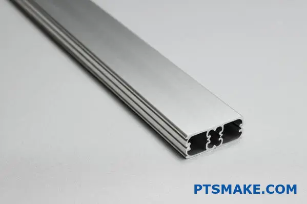
Yes, polycarbonate is highly machinable. It can be drilled, milled, turned, and tapped with standard metal-working equipment while offering excellent dimensional stability and maintaining its optical clarity during the machining process.
At PTSMAKE, we machine polycarbonate components daily for various industries. This versatile thermoplastic offers a great balance of properties that make it ideal for precision parts. If you’re considering polycarbonate for your project, keep reading to learn about its machining characteristics, best practices, and application possibilities that could benefit your specific requirements.
Is Polycarbonate Easy To Machine?
Have you ever struggled with machining polycarbonate, only to end up with melted edges, stress cracks, or parts that simply don’t meet specifications? The frustration of wasted materials and time can be overwhelming, especially when deadlines are looming and clients are waiting.
Polycarbonate is moderately easy to machine with the right techniques and tools. While its toughness and heat sensitivity present challenges, proper cooling, sharp tools, moderate speeds, and controlled feed rates will produce excellent results. Compared to other plastics, it requires more careful handling but offers superior durability and optical clarity.
Understanding Polycarbonate as an Engineering Material
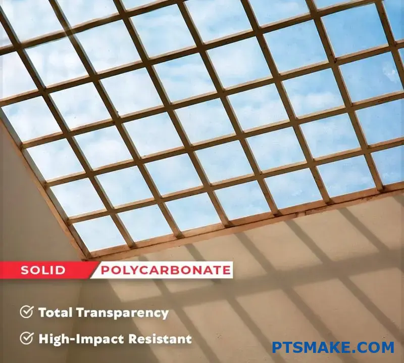
Polycarbonate (PC) stands out among engineering plastics for its exceptional combination of properties. As someone who has worked with countless materials during my time at PTSMAKE, I’ve come to appreciate the unique position PC holds in the manufacturing world. It offers remarkable impact resistance—250 times stronger than glass and 30 times stronger than acrylic. This makes it ideal for applications requiring both transparency and durability.
The material maintains its properties across a wide temperature range (-40°F to 280°F), making it suitable for diverse environments. Its natural transparency combined with excellent light transmission (88-91%) makes it perfect for optical applications. However, these same properties that make polycarbonate valuable also create specific challenges during machining.
Physical Properties Affecting Machinability
Polycarbonate’s viscoelastic behavior1 directly impacts how it responds to machining operations. This material has a relatively low glass transition temperature (approximately 147°C/297°F), which means it can easily soften during machining if heat builds up. Here’s how its key properties affect machining:
| Property | Value | Impact on Machining |
|---|---|---|
| Tensile Strength | 55-75 MPa | Requires proper tool rigidity |
| Thermal Conductivity | 0.19-0.22 W/m·K | Poor heat dissipation requires cooling |
| Coefficient of Thermal Expansion | 65-70 × 10^-6/°C | Dimensional stability challenges |
| Glass Transition Temperature | 147°C | Risk of heat deformation |
| Hardness (Rockwell) | M70-M75 | Moderate tool wear |
These properties create a dichotomy—polycarbonate is simultaneously tough enough to resist cutting forces yet sensitive enough to thermal damage to require careful process control.
Comparing PC Machining to Other Plastics
Polycarbonate falls in the middle range of machinability when compared to other common engineering plastics. Based on my experience with various plastic machining projects, here’s how it compares:
Easier to Machine Than PC
- Acetal (Delrin): Machines like butter with excellent dimensional stability
- HDPE: Very forgiving with low friction and easy chip evacuation
- ABS: Good machinability with lower heat sensitivity
Similar Machinability to PC
- Nylon: Requires similar cooling considerations
- PMMA (Acrylic): Similar tool requirements but more brittle
More Difficult to Machine Than PC
- PEEK: Requires higher cutting forces and specialized tooling
- PEI (Ultem): Higher processing temperatures and tool wear
- PTFE (Teflon): Difficult due to its deformation under pressure
Essential Techniques for Successful PC Machining
Over my 15+ years in precision manufacturing, I’ve developed specific approaches for working with polycarbonate. These techniques significantly improve results:
Cooling Strategies
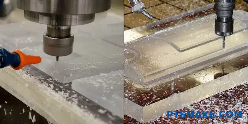
The number one rule for polycarbonate machining is effective cooling. Compressed air cooling works well for light cuts, while mist cooling with water-soluble coolants is preferable for deeper operations. Flood cooling should be avoided as it can cause stress cracking due to thermal shock.
Tool Selection and Preparation
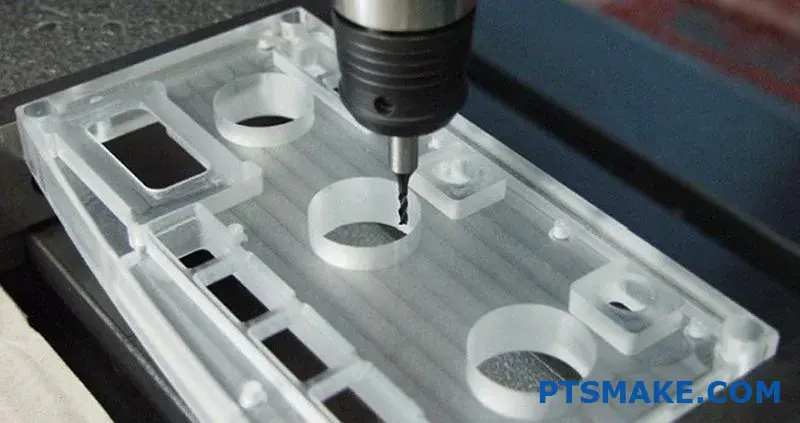
Sharp cutting edges are essential. I recommend carbide tools with polished cutting surfaces and relief angles of 15-20 degrees. For drilling, specialized plastic-cutting drill bits with steeper point angles (90-118°) prevent grabbing and chipping.
Speed and Feed Considerations
For optimal results with polycarbonate, I follow these guidelines:
- Cutting speeds: 500-1000 ft/min (lower than for softer plastics)
- Feed rates: Moderate to high to prevent heat buildup
- Depth of cut: Multiple light passes rather than single deep cuts
- RPM for drilling: 300-1500 RPM depending on hole diameter
These parameters help maintain the balance between efficient material removal and avoiding heat-related issues like melting or stress.
Common Challenges and Solutions
Despite proper techniques, certain challenges remain when machining polycarbonate:
Edge melting: Often occurs during routing or high-speed operations. Solution: Sharp tools, proper cooling, and increased feed rates relative to speed.
Stress cracking: Appears hours or days after machining. Solution: Anneal parts before final machining and use proper tool geometry.
Chipping: Particularly common at entry/exit points during drilling. Solution: Use backing materials and specialized drill geometries.
Dimensional instability: Parts may warp after machining. Solution: Allow for stress relief between roughing and finishing operations.
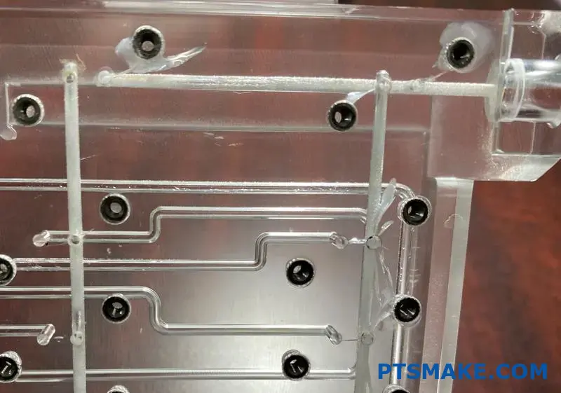
At PTSMAKE, we’ve developed specialized fixtures and processing protocols to address these challenges, ensuring consistent quality even for the most demanding polycarbonate components.
What Is Advantage Of Polycarbonate?
Have you ever struggled to find a material that combines exceptional durability with optical clarity? Or searched for something that can withstand extreme impacts and temperatures without breaking the bank? The frustration of selecting the perfect material for critical applications can be overwhelming.
Polycarbonate offers outstanding advantages including exceptional impact resistance (250 times stronger than glass), optical clarity (89% light transmission), temperature stability (-40°F to 280°F), lightweight properties, design flexibility, and cost-effectiveness for various industrial applications.
Remarkable Impact Resistance
Polycarbonate’s most impressive characteristic is its extraordinary impact resistance. This engineering thermoplastic can withstand forces that would shatter or crack other materials like glass or acrylic. With impact strength approximately 250 times greater than glass and 30 times greater than acrylic, polycarbonate stands out as an exceptional choice for applications requiring durability.
In my experience working with manufacturers across different industries, this property makes polycarbonate ideal for safety equipment, machine guards, and protective barriers. At PTSMAKE, we’ve implemented polycarbonate in numerous projects where impact resistance was critical, such as protective housings for industrial machinery and components for automotive applications.
Real-World Impact Resistance Applications
- Safety Shields: Used in industrial settings to protect workers from flying debris
- Bulletproof Windows: Applied in security vehicles and buildings
- Sporting Equipment: Utilized in hockey face shields and protective gear
- Machine Guards: Prevents injuries while allowing visibility of operating components
Optical Clarity & Light Transmission
Another significant advantage of polycarbonate is its impressive optical clarity. With light transmission rates of approximately 89%, polycarbonate delivers glass-like transparency. This property makes it suitable for applications where visibility is crucial while maintaining strength requirements.
The material’s ability to transmit light without significant distortion makes it excellent for dioptric applications2 such as lenses, light diffusers, and transparent covers. When we machine polycarbonate parts at PTSMAKE, special care is taken to maintain this optical clarity through proper tooling and finishing processes.
Temperature Stability
Polycarbonate demonstrates exceptional thermal stability across a wide temperature range. It can withstand temperatures from approximately -40°F (-40°C) to 280°F (138°C) without significant degradation of mechanical properties. This makes it suitable for applications exposed to varying or extreme temperatures.
Temperature Performance Comparison
| Material | Lower Temperature Limit | Upper Temperature Limit | Heat Deflection Temperature |
|---|---|---|---|
| Polycarbonate | -40°F (-40°C) | 280°F (138°C) | 270°F (132°C) |
| Acrylic | -4°F (-20°C) | 180°F (82°C) | 190°F (88°C) |
| ABS | -4°F (-20°C) | 176°F (80°C) | 190°F (88°C) |
| Glass | Extremely Low | 800°F+ (427°C+) | N/A |
This temperature stability is particularly valuable in automotive components, electronic housings, and outdoor enclosures. I’ve seen polycarbonate perform exceptionally well in challenging environments where temperature fluctuations would cause other materials to fail.
Lightweight Properties
Polycarbonate offers significant weight advantages compared to traditional materials like glass. With a density of approximately 1.2 g/cm³, it’s less than half the weight of glass, which typically has a density around 2.5 g/cm³. This weight reduction is crucial for:
- Reducing transportation costs
- Improving fuel efficiency in automotive applications
- Easing installation processes
- Decreasing structural load requirements
These lightweight properties make polycarbonate particularly attractive for transportation applications, portable devices, and large structural components where weight matters.
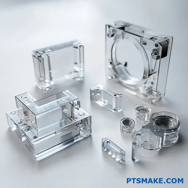
Design Flexibility
One of the most practical advantages of polycarbonate is its remarkable design flexibility. The material can be:
- Easily machined with appropriate tooling and cooling
- Thermoformed into complex shapes
- Injection molded with high precision
- Bent and formed at room temperature (in sheet form)
- Bonded using various adhesives or welding techniques
At PTSMAKE, we leverage these properties to help engineers create complex parts that would be difficult or impossible to produce with other materials. The material’s ability to be precisely machined allows for tight tolerances and intricate features that meet demanding specifications.
Cost-Effectiveness
While polycarbonate may have a higher initial material cost than some alternatives, its overall cost-effectiveness often makes it the more economical choice when considering:
- Extended service life due to durability
- Reduced replacement frequency
- Lower installation costs due to lighter weight
- Simplified fabrication of complex parts
- Potential for part consolidation
In manufacturing environments, these factors often result in lower total cost of ownership compared to seemingly cheaper alternatives that require frequent replacement or more complex fabrication.
UV Resistance (With Proper Additives)
Standard polycarbonate is susceptible to UV degradation, which can cause yellowing and brittleness over time. However, with proper UV-resistant additives or coatings, polycarbonate can maintain its properties when exposed to sunlight. Many polycarbonate products now come with co-extruded UV-protective layers that significantly extend outdoor service life.
Best Clear Plastic For Machining?
Have you ever struggled to choose the right clear plastic for your precision machining project? The frustration of selecting a material that checks all boxes—optical clarity, dimensional stability, and machinability—can be overwhelming when facing dozens of options with confusing technical specifications.
For machining applications requiring optical clarity, polycarbonate (PC) stands out as the best overall clear plastic due to its exceptional combination of transparency, impact resistance, and machining properties. For precision applications, acrylic (PMMA) offers superior optical clarity, while PETG provides a cost-effective alternative for less demanding projects.
Comparing Top Clear Plastics for Machining
When selecting clear plastics for machining, understanding the specific properties and performance characteristics of each material is crucial. After working with hundreds of different manufacturing projects, I’ve found that the "best" material always depends on your specific application requirements.
Polycarbonate (PC): The Versatile Performer
Polycarbonate has earned its position as my go-to recommendation for most clear plastic machining applications. With its impressive 89% light transmission and exceptional impact strength (250 times that of glass), it delivers unmatched durability while maintaining excellent optical properties.
From a machining perspective, PC offers several advantages:
- Maintains dimensional stability during complex machining operations
- Responds well to both conventional and CNC machining techniques
- Can be drilled, milled, and tapped without special tooling
- Tolerates moderate heat generated during machining without warping
However, PC isn’t without limitations. It’s more susceptible to chemical attacks than some alternatives, and certain cutting fluids can cause crazing or micro-cracking. At PTSMAKE, we’ve found that using specific coolant formulations and maintaining optimal cutting speeds prevents these issues.
Acrylic (PMMA): The Optical Champion
When optical clarity is the absolute priority, acrylic (PMMA) frequently outperforms other options. With 92% light transmission and excellent UV resistance, it delivers exceptional clarity and color stability over time.
Acrylic machining characteristics include:
- Excellent surface finish directly from machining operations
- Good dimensional stability for precision components
- Superior thread quality when tapped
- Low moisture absorption ensuring consistent properties
The primary challenges with acrylic machining come from its brittle nature compared to PC. It requires careful feed rates and sharp tooling to prevent chipping or cracking. I’ve found that using specialized acrylic-cutting end mills with polished flutes significantly reduces these risks.
PETG: The Cost-Effective Alternative
For projects with tighter budgets but still requiring decent clarity, PETG (Polyethylene Terephthalate Glycol) offers a practical middle ground. With about 86% light transmission and good impact resistance, it serves many applications adequately.
PETG machining benefits include:
- Lower material cost than PC or premium acrylics
- Good machinability with standard tooling
- Chemical resistance superior to acrylic
- Lower melting point, requiring careful speed control
Comparing Key Properties
Here’s a comparative analysis of the most common clear plastics used in machining applications:
| Material | Light Transmission | Impact Strength | Chemical Resistance | Machining Difficulty | Relative Cost |
|---|---|---|---|---|---|
| Polycarbonate (PC) | 89% | Excellent | Moderate | Medium | High |
| Acrylic (PMMA) | 92% | Fair | Good (except solvents) | Medium-High | Medium |
| PETG | 86% | Good | Good | Low-Medium | Low |
| COC/COP | 92% | Fair | Excellent | High | Very High |
| Ultem (PEI) | 85% (amber tint) | Very Good | Excellent | High | Very High |
Specialized Applications and Material Selection
Medical and Food-Grade Requirements
For applications requiring biocompatibility3 in medical devices or food-contact safety, material selection becomes even more critical. Medical-grade polycarbonate and specific grades of acrylic are FDA-compliant and can withstand sterilization processes.
At PTSMAKE, we maintain separate machining stations for medical-grade plastics to prevent cross-contamination, ensuring products meet strict regulatory requirements.
Optical Instruments and Lenses
For optical components requiring exceptional clarity and precision, optical-grade acrylic or specialty materials like Cyclic Olefin Copolymer (COC) offer superior performance. These materials can be machined to extremely tight tolerances while maintaining excellent optical properties.
The machining approach differs significantly for optical applications:
- Slower cutting speeds with high-polish tooling
- Multiple finishing passes at progressively finer cuts
- Specific tool geometries to minimize stress on the material
- Optional flame polishing for achieving optical-quality surfaces
Electronic Enclosures and Displays
For electronic housings and displays, I typically recommend polycarbonate due to its combination of clarity, impact resistance, and flame-retardant properties (when using FR grades). Its good electrical insulation properties make it ideal for these applications.
Machining Techniques for Clear Plastics
Regardless of material choice, certain machining techniques consistently produce better results with clear plastics:
- Use sharp tooling: Dull tools generate excessive heat and can cause melting or crazing
- Maintain appropriate speeds and feeds: Generally slower than metals but fast enough to prevent melting
- Apply adequate cooling: Air cooling for light operations, mist cooling for more aggressive cuts
- Consider thermal expansion: Allow for material movement during machining
- Support thin sections: Prevent vibration and chatter that can lead to cracking
Final Considerations for Material Selection
When making your final material selection, I recommend weighing these factors:
- Application requirements: What level of clarity, impact resistance, and chemical exposure will the part experience?
- Budget constraints: Is the premium performance of PC or specialty materials justified for your application?
- Production volume: Will the material be machined for prototypes only, or is this for ongoing production?
- Secondary operations: Will the part require bonding, polishing, or other post-processing?
Based on my experience working with clients across various industries, clearly defining these requirements upfront saves considerable time and expense during the manufacturing process.
Machining Acrylic Vs Polycarbonate?
Ever struggled to choose between acrylic and polycarbonate for your machining project? Have you watched your perfectly designed parts crack during machining or fail during use because you selected the wrong plastic material? The confusion between these similar-looking materials can lead to costly mistakes and project delays.
When machining acrylic vs polycarbonate, acrylic is easier to machine with better optical clarity but is more brittle, while polycarbonate offers superior impact resistance and durability but requires careful machining to prevent melting. Your choice depends on whether you prioritize aesthetics and machinability (acrylic) or strength and durability (polycarbonate).
Key Differences in Machining Properties
After working with both materials extensively in custom manufacturing projects, I’ve developed a deep understanding of how each material behaves during the machining process. The fundamental differences in their molecular structure directly affect how they respond to cutting tools and heat.
Cutting Characteristics
Acrylic (PMMA) machines beautifully – it cuts cleanly with minimal effort, producing crisp edges and excellent surface finishes. The material cuts somewhat like a hard cheese, with chips that break away cleanly. This makes acrylic ideal for intricate designs where precise detail is critical.
Polycarbonate (PC), by contrast, presents more challenges. Its incredible toughness means cutting tools must work harder, generating more friction and heat. The material has a tendency to gum up4 during machining, potentially causing tool binding and poor surface finishes if machining parameters aren’t properly adjusted.
Heat Sensitivity
Temperature management is crucial when machining these materials:
Acrylic: Has a higher heat resistance during machining with a glass transition temperature around 105°C (221°F). It’s less likely to deform from frictional heat but more prone to cracking if tools are dull or feed rates are too aggressive.
Polycarbonate: With a lower glass transition temperature (approximately 147°C/297°F), polycarbonate is more susceptible to heat-related issues. It can quickly soften and melt during machining if cutting speeds are too high or cooling is insufficient.
Tool Selection and Settings
Based on my experience at PTSMAKE, proper tool selection dramatically impacts results:
| Parameter | Acrylic | Polycarbonate |
|---|---|---|
| Recommended Cutting Speed | 500-1000 m/min | 300-500 m/min |
| Tool Material | HSS or Carbide | Sharp Carbide preferred |
| Coolant Usage | Optional, air cooling often sufficient | Strongly recommended |
| Feed Rate | Can be relatively aggressive | Must be moderate to prevent melting |
| Tool Geometry | Standard geometry works well | Sharp tools with positive rake angles |
Material Behavior During Different Machining Operations
Milling Considerations
When milling acrylic, I’ve found you can achieve near-optical finishes directly from the cutter with proper speeds and feeds. Single-flute cutters often work best as they provide efficient chip evacuation, preventing heat buildup.
For polycarbonate milling, coolant becomes essential. At PTSMAKE, we’ve achieved excellent results using compressed air cooling combined with lower spindle speeds. This prevents the characteristic melting that can occur when machining PC components.
Drilling Challenges
Drilling highlights the contrasting properties of these materials:
Acrylic tends to chip and crack around drill exit points. I recommend using specialized plastic drill bits with modified point angles (60-90°) and reduced speeds when approaching the exit.
Polycarbonate’s flexibility makes it more forgiving during drilling, but its tendency to grab the drill bit can cause issues. Peck drilling with frequent chip clearing prevents heat buildup and produces cleaner holes.
Edge Finishing
Post-machining finishing reveals another key difference:
Acrylic edges can be flame polished to achieve glass-like clarity – something impossible with polycarbonate. For PC parts, mechanical polishing is necessary, requiring more labor and processing time.
Application-Specific Considerations
Optical Applications
For optical components where clarity is paramount, acrylic has distinct advantages. It transmits 92% of visible light (compared to polycarbonate’s 88%) and maintains exceptional clarity over time. This makes it preferred for display cases, architectural features, and optical lenses.
Polycarbonate, while still transparent, has a slight yellowish tint that becomes more pronounced in thicker sections. This limits its use in premium optical applications despite its superior impact resistance.
Structural Components
When designing load-bearing or high-impact components, polycarbonate’s exceptional toughness (250 times that of glass and 30 times that of acrylic) makes it the clear choice. I’ve seen polycarbonate parts withstand impacts that would shatter acrylic instantly.
Environmental Factors
Consider your application’s operating environment:
- Outdoor applications: Polycarbonate stands up better to temperature fluctuations but requires UV stabilization to prevent yellowing
- Chemical exposure: Acrylic resists many chemicals that attack polycarbonate
- High-stress environments: Polycarbonate’s superior fatigue resistance makes it better for parts under constant load
Cost-Efficiency Analysis
In my 15+ years of experience, I’ve found that material selection significantly impacts total project costs beyond just raw material prices. Polycarbonate typically costs 20-30% more than acrylic, but the calculation isn’t that simple.
Acrylic’s ease of machining means faster production times and less tool wear, potentially offsetting its lower material cost advantage for complex parts. Meanwhile, polycarbonate’s durability might provide longer service life, making it more economical for certain applications despite higher initial costs.
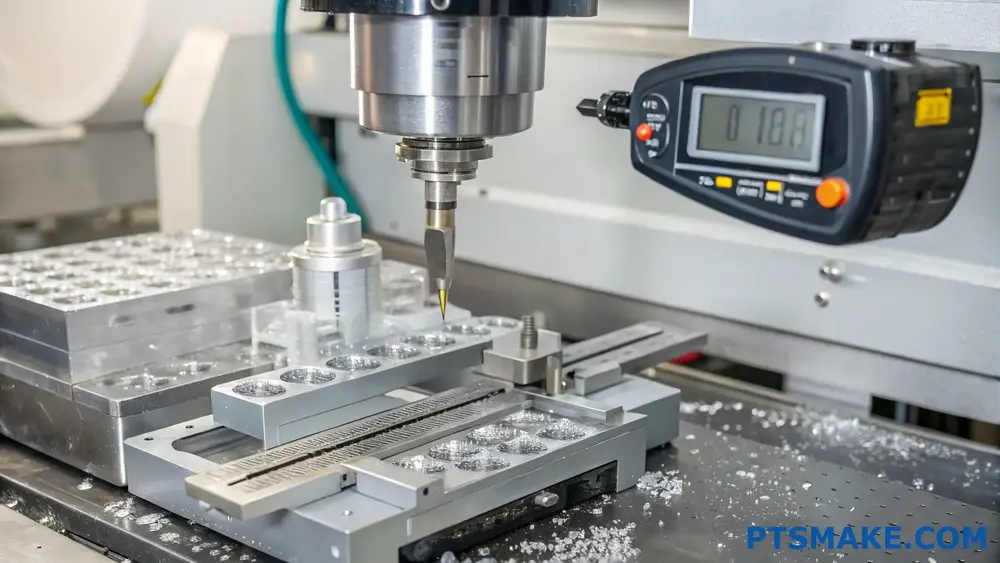
Machining Polycarbonate Speeds And Feeds?
Have you ever watched your polycarbonate workpiece melt before your eyes during machining? Or dealt with the frustration of chipped edges and poor surface finishes despite using what you thought were appropriate settings? These issues can quickly turn a straightforward project into a costly nightmare.
When machining polycarbonate, optimal speeds and feeds typically fall between 500-1000 RPM with feed rates of 0.005-0.015 inches per revolution. Using sharp carbide tools, maintaining adequate cooling, and employing moderate cutting depths helps prevent melting and chipping while ensuring quality results.
Understanding Speed and Feed Relationships for Polycarbonate
Machining polycarbonate successfully requires balancing several critical factors. Unlike metals, PC has a relatively low melting point (approximately 155°C) and behaves differently under cutting forces. In my experience at PTSMAKE, finding the right speed and feed combination is essential for quality results.
The relationship between cutting speed and feed rate creates what I call the "PC sweet spot." Too fast, and friction generates excessive heat that melts the material. Too slow, and the tool might rub rather than cut, creating similar heat issues. This thermoplastic behavior5 makes PC particularly sensitive to machining parameters.
Recommended Speed Ranges for Different PC Grades
Not all polycarbonate is created equal. The grade and thickness significantly impact machining parameters. Here’s a breakdown of recommended cutting speeds based on my work with various PC grades:
| PC Grade | Thickness (mm) | Cutting Speed (SFM) | RPM Range (1/2" Tool) |
|---|---|---|---|
| Standard PC | 1-5 | 300-500 | 800-1200 |
| Optical PC | 1-5 | 250-400 | 600-1000 |
| Flame Retardant PC | 1-5 | 350-550 | 900-1300 |
| Standard PC | 6-12 | 250-450 | 700-1100 |
| Optical PC | 6-12 | 200-350 | 500-900 |
| Flame Retardant PC | 6-12 | 300-500 | 800-1200 |
Feed Rate Considerations for CNC Machining Polycarbonate
Feed rate—the speed at which the tool moves through the material—is just as important as spindle speed. I’ve found that starting with conservative feed rates and increasing gradually produces the best results.
For most polycarbonate machining operations, I recommend:
Milling Feed Rates
| Operation Type | Tool Diameter (mm) | Feed Rate (mm/min) | Chip Load (mm/tooth) |
|---|---|---|---|
| Roughing | 6 | 600-900 | 0.05-0.08 |
| Roughing | 12 | 900-1200 | 0.08-0.12 |
| Finishing | 6 | 400-700 | 0.03-0.06 |
| Finishing | 12 | 600-900 | 0.05-0.09 |
Drilling Feed Rates
| Drill Diameter (mm) | Feed Rate (mm/min) | Recommended RPM |
|---|---|---|
| 3 | 60-100 | 2000-2800 |
| 6 | 100-160 | 1500-2300 |
| 10 | 140-200 | 1200-1800 |
| 12+ | 180-250 | 800-1400 |
One thing I’ve learned through numerous PC machining projects is that slower feed rates generally produce better surface finishes, but too slow can cause material heating. At PTSMAKE, we often start at the lower end of these ranges and adjust upward based on results.
Tool Selection Impact on Speeds and Feeds
Tool material, geometry, and condition dramatically affect appropriate speeds and feeds. For polycarbonate machining, I strongly recommend:
- Tool Material: Carbide tools generally outperform HSS for PC machining due to better heat dissipation and edge retention
- Cutting Edges: Sharp cutting edges with positive rake angles (10-15°) reduce cutting forces
- Flute Count: Fewer flutes (2-3) for improved chip evacuation in deeper cuts
- Tool Coatings: Uncoated tools are typically preferred for PC as they generate less heat
When using a high-quality carbide end mill specifically designed for plastics, you can often run at the higher end of the recommended speed ranges without issues.
Cooling Strategies for Optimal Results
Proper cooling is perhaps the most critical factor in successful polycarbonate machining. Excessive heat not only ruins your workpiece but can create internal stresses that lead to later part failures.
Effective Cooling Methods
- Compressed Air: Clean, dry air directed at the cutting zone works well for thin PC sections
- Mist Cooling: Water-based mist cooling provides excellent results without chemical contamination
- Flood Coolant: Used for heavy-duty operations, though ensure your coolant is compatible with PC
- Peck Drilling: For deeper holes, use peck drilling cycles to prevent heat buildup
- Programmed Pauses: For longer operations, program brief pauses to allow heat dissipation
I’ve found that a combination of compressed air and occasional pauses works best for most PC machining applications, especially for precision components.
Signs Your Speeds and Feeds Need Adjustment
Recognizing when your machining parameters need adjustment can save material and time. Watch for these telltale signs:
- Melted edges: Immediate indicator of excessive speed or inadequate cooling
- Chipping: Often indicates too aggressive feed rates or dull tooling
- Fuzzy surface finish: May suggest feed rate is too low or tool is dull
- Tool loading: Material buildup on cutting edges indicates improper chip evacuation
- Squealing sound: High-pitched noise during cutting usually means excessive speed
When these issues arise, I typically reduce speed first, then adjust feed rate if necessary. Small, incremental adjustments often make a significant difference in outcome quality.
How To Prevent Stress Cracks In PC Machining?
Have you ever spent hours meticulously machining a polycarbonate part, only to discover hairline cracks appearing days later? Or watched in frustration as your perfectly designed PC components develop mysterious fractures during assembly? These stress cracks can turn promising projects into costly failures.
Preventing stress cracks in PC machining requires controlled cutting parameters, proper tool selection, and adequate cooling. Avoid excessive heat buildup by using sharp tools, moderate speeds, and consistent feeds. Allow proper stress relief before and after machining, and implement gradual cooling to prevent internal stresses.
Understanding the Nature of Stress Cracks in PC
Stress cracks in polycarbonate components don’t always appear immediately after machining. They can develop hours, days, or even weeks later, making them particularly troublesome to diagnose and prevent. These cracks occur when internal stresses within the material exceed its structural integrity limits.
Polycarbonate is an amorphous thermoplastic known for its excellent impact resistance and optical clarity. However, this versatility comes with sensitivity to machining conditions. During CNC operations, improper techniques can introduce or amplify internal stress patterns6 within the material, which later manifest as visible cracks.
In my experience working with precision PC components, I’ve found that these cracks typically follow predictable patterns. They often originate at sharp corners, holes, or areas where material thickness changes abruptly. Understanding these patterns helps us develop effective prevention strategies.
Common Causes of Stress Cracking
Several factors contribute to stress crack formation during PC machining:
- Heat Generation: Excessive heat from high-speed machining can create thermal stress gradients
- Improper Tooling: Dull tools create friction and heat rather than clean cuts
- Aggressive Cutting Parameters: Removing too much material at once creates mechanical stress
- Inadequate Cooling: Insufficient or inconsistent cooling leads to uneven thermal expansion
- Improper Clamping: Excessive clamping force introduces mechanical stress before cutting begins
Critical Prevention Strategies
Optimizing Cutting Parameters
The key to stress-free PC machining lies in selecting appropriate cutting parameters. At PTSMAKE, we’ve refined these parameters through extensive testing:
| Parameter | Recommended Range | Impact on Stress |
|---|---|---|
| Cutting Speed | 200-400 SFM | Higher speeds increase heat generation |
| Feed Rate | 0.001-0.005 in/tooth | Too slow causes rubbing; too fast causes tearing |
| Depth of Cut | <0.125" per pass | Deeper cuts create more internal stress |
| Tool Rake Angle | 0-5° positive | Improves chip evacuation and reduces heat |
Maintaining consistent feed rates is particularly important. Hesitation or dwelling in one spot can generate localized heat buildup, creating stress concentrations that lead to cracks. I recommend programming smooth, continuous toolpaths whenever possible.
Selecting Proper Tooling
Tool selection significantly impacts stress formation. Single-flute end mills specifically designed for plastics perform exceptionally well for PC machining. These tools provide:
- Enhanced chip evacuation
- Reduced friction and heat generation
- Cleaner cutting action with less material deformation
I strongly advise against using tools designed for metals when machining PC. While they may cut the material, they typically have geometry that creates excessive friction and heat, leading to stress buildup.
Implementing Effective Cooling Strategies
Proper cooling is perhaps the most critical aspect of preventing stress cracks. For optimal results:
- Use compressed air cooling directed at the cutting zone
- Avoid flood coolants that can cause thermal shock
- Implement mist cooling systems with compatible lubricants
- Allow for gradual cooling after machining is complete
One technique I’ve found particularly effective is programming periodic "cooling passes" during complex operations. These light finishing passes generate minimal heat while allowing previous cuts to cool slightly.
Pre and Post-Machining Considerations
Material Preparation
Stress prevention begins before the first cut. Consider these pre-machining steps:
- Anneal raw PC stock before machining to relieve existing stresses
- Allow material to acclimate to shop temperature (24 hours minimum)
- Inspect for existing stress patterns using polarized light when possible
- Select appropriate grade of PC for your application
Post-Machining Treatment
After machining, proper handling is essential:
- Allow gradual cooling in a temperature-controlled environment
- Implement stress relief annealing for critical components (heating to just below glass transition temperature, then cooling slowly)
- Avoid chemical exposure during the cooling period
- Minimize mechanical stress during part removal and handling
Environmental Factors
The machining environment itself plays a role in stress crack formation. Maintain consistent ambient temperature and humidity in your machining area. Temperature fluctuations during the machining process can introduce thermal stresses that contribute to cracking.
At PTSMAKE, we maintain our machining facilities at controlled temperature and humidity levels specifically to ensure consistent results when working with sensitive materials like polycarbonate.
Quality Control Measures
Implementing proper inspection protocols helps identify potential stress issues before they develop into cracks:
- Visual inspection under bright, directional lighting
- Polarized light testing to reveal internal stress patterns
- Holding period of 24-48 hours before final inspection or assembly
- Controlled test conditions that replicate end-use environments
These measures have helped us significantly reduce stress-related failures in critical PC components we produce.
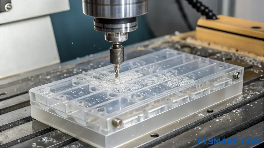
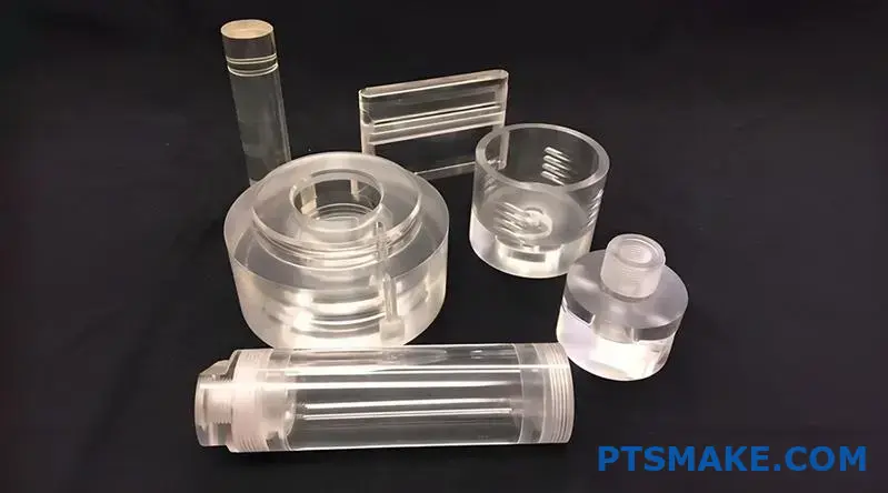
What Surface Finish Options Exist For PC Machining?
Ever struggled with achieving the perfect finish on your PC machining projects? Have you found yourself wondering which surface treatment would best suit your polycarbonate components, only to be overwhelmed by conflicting advice and technical jargon?
Surface finish options for PC machining include sandblasting, bead blasting, polishing, painting, anodizing, texturing, powder coating, and chemical treatments. Each technique offers unique aesthetic and functional properties that can enhance polycarbonate parts based on specific application requirements.
Understanding Surface Finish Options for PC Machining
When working with polycarbonate (PC) materials in CNC machining, the surface finish you select can dramatically impact both the appearance and functionality of your final product. PC is a versatile thermoplastic known for its exceptional clarity, impact resistance, and thermal stability, making it popular across industries from automotive to medical devices. However, its true potential is often realized through the appropriate surface finish.
Mechanical Surface Finish Options
Sandblasting
Sandblasting creates a uniform matte finish on PC parts by propelling fine sand particles at high pressure against the surface. This technique effectively:
- Removes machining marks and surface imperfections
- Creates a consistent non-reflective surface
- Enhances paint adhesion for subsequent finishing
- Provides light diffusion properties for optical applications
At PTSMAKE, I’ve found sandblasting particularly valuable for dashboard components and medical device housings where glare reduction is crucial.
Bead Blasting
Similar to sandblasting but using round glass beads instead of sand, bead blasting delivers a smoother, more refined matte finish. The rounded media creates:
- A silky, uniform appearance
- Reduced surface roughness compared to sandblasting
- Less aggressive material removal
- Excellent substrate preparation for coatings
This finish is ideal for consumer electronics enclosures where a premium feel is essential.
Polishing
Polishing PC parts ranges from basic buffing to mirror-like finishes through progressive abrasive steps. The polishing progression7 typically involves:
- Rough abrasive removal of machining marks
- Medium grit smoothing
- Fine grit polishing
- Final buffing with compounds
The results can range from satin to high-gloss mirror finishes, with the latter showcasing PC’s natural optical clarity.
Chemical and Coating Finishes
Painting
Painting PC components offers virtually unlimited color options and can provide:
- UV protection for outdoor applications
- Specific aesthetic requirements
- Additional layer of protection
- Custom branding opportunities
Modern paint systems designed for polycarbonate adhere exceptionally well when properly applied after appropriate surface preparation.
Anodizing-Like Treatments
While true anodizing only works on metals like aluminum, similar effect treatments exist for PC that can:
- Create metallic appearances
- Improve hardness
- Enhance scratch resistance
- Provide decorative finishes
These treatments involve special coatings that mimic anodized appearances while working with PC’s polymer structure.
Texturing
Surface texturing can be applied through either the machining process or post-processing:
| Texturing Method | Characteristics | Common Applications |
|---|---|---|
| EDM Texturing | Precise, repeatable patterns | Medical devices, grip surfaces |
| Chemical Texturing | Uniform micro-texture | Optical diffusion, anti-glare surfaces |
| Laser Texturing | High precision, complex patterns | Branding, functional features |
| Manual Texturing | Artistic, unique finishes | Custom projects, decorative elements |
Specialized PC Finishes
Powder Coating
Though traditionally associated with metals, specialized powder coating formulations for PC can provide:
- Exceptional durability
- Chemical resistance
- Textured finishes
- Environmental benefits (no VOCs)
This process requires careful temperature control since PC has lower heat resistance than metals.
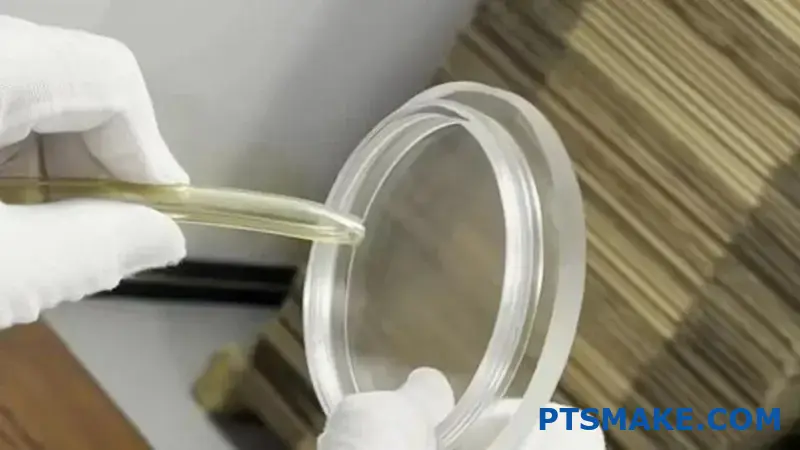
Vapor Polishing
This chemical process exposes PC to solvent vapors that momentarily soften the surface, allowing surface tension to create a smooth, glossy finish. Benefits include:
- Optically clear surfaces
- Removal of fine machining marks
- Enhanced part transparency
- Improved aesthetic quality
I’ve seen remarkable results with vapor polishing on medical components and display covers where optical clarity is paramount.
Anti-Reflective Coatings
For optical applications, specialized anti-reflective coatings can be applied to machined PC parts to:
- Reduce glare
- Improve light transmission
- Enhance display readability
- Minimize interference patterns
These multi-layer coatings are particularly valuable in instrument panels and medical diagnostic equipment.
Selecting the Right Surface Finish
Choosing the appropriate surface finish for your PC machined parts depends on several factors:
- Functional requirements (optical clarity, grip, wear resistance)
- Aesthetic considerations
- Environmental exposure conditions
- Cost constraints
- Production volume
At PTSMAKE, we work closely with clients to determine the optimal finishing approach based on their specific application needs. With our 15+ years of experience in PC machining, we’ve developed expertise in applying these various finishes to achieve both form and function.
How To Ensure Dimensional Accuracy In PC Machining?
Have you ever received PC machined parts that simply don’t fit together as designed? Or spent hours troubleshooting assembly issues only to discover that key dimensions are off by mere fractions of a millimeter? Dimensional inaccuracies can transform a promising project into a frustrating and costly setback.
Ensuring dimensional accuracy in PC machining requires a comprehensive approach involving proper material selection, advanced tooling strategies, temperature control, and meticulous inspection protocols. By implementing these practices throughout the production process, manufacturers can consistently achieve tolerances as tight as ±0.05mm even with PC’s challenging properties.
Understanding PC Material Properties and Their Impact on Dimensional Accuracy
Polycarbonate (PC) stands out among engineering plastics for its exceptional combination of strength, transparency, and heat resistance. However, these beneficial properties come with particular machining challenges that directly impact dimensional accuracy. In my experience working with various plastic materials, PC presents some unique considerations due to its viscoelastic behavior8 during machining.
PC has a relatively high thermal expansion coefficient (around 65-70 × 10^-6/°C), making it susceptible to dimensional changes during temperature fluctuations. This becomes especially critical when machining complex parts with tight tolerances. The material also exhibits stress relaxation after machining, which can lead to dimensional shifts hours or even days after production.
Key Material Properties Affecting Dimensional Accuracy in PC Machining
When planning for dimensional accuracy with PC, I always consider these critical material characteristics:
- Thermal Sensitivity: PC expands and contracts significantly with temperature changes
- Moisture Absorption: Can absorb up to 0.35% moisture, affecting dimensions
- Internal Stress: Higher internal stress compared to many other plastics
- Hardness/Rigidity: Medium to high rigidity that can vary with grade and additives
These properties directly influence machining strategies, tooling choices, and quality control protocols. For instance, at PTSMAKE, we’ve developed specific cutting parameters that account for PC’s thermal sensitivity, ensuring minimal heat generation during machining operations.
Optimizing CNC Programming for Precision PC Components
Precise CNC programming is the foundation of dimensional accuracy. For PC machining, standard approaches often fall short due to the material’s unique properties. I’ve found that optimizing the following parameters makes a substantial difference:
Feed Rate and Cutting Speed Considerations
The balance between feed rate and cutting speed is crucial for PC machining. Too aggressive cutting generates excessive heat, leading to thermal expansion during machining and unpredictable shrinkage afterward. For reference, here’s a table of recommended parameters based on our experience:
| Operation Type | Cutting Speed (m/min) | Feed Rate (mm/rev) | Depth of Cut (mm) |
|---|---|---|---|
| Roughing | 150-200 | 0.1-0.15 | 1.0-2.0 |
| Semi-finishing | 200-250 | 0.05-0.1 | 0.5-1.0 |
| Finishing | 250-300 | 0.01-0.05 | 0.1-0.5 |
These values serve as starting points and may require adjustment based on specific PC grades and machine capabilities. The key is maintaining consistent heat generation throughout the machining process.
Tool Path Strategies for Complex PC Parts
Tool path planning significantly impacts dimensional accuracy, especially for complex geometries. I recommend:
- Climb milling over conventional milling when possible
- Continuous tool engagement to maintain consistent cutting forces
- Smaller stepovers (15-20% of tool diameter) for final passes
- Multiple finishing passes with decreasing depth of cut
These strategies help minimize internal stress buildup and provide more consistent material removal rates, which is essential for maintaining dimensional stability in PC components.
Advanced Tooling Selection for PC Machining
Selecting the right cutting tools dramatically influences achievable tolerances. After years of experimentation, I’ve identified several critical factors:
Tool Geometry Considerations
For PC machining, I’ve found these tool characteristics deliver superior dimensional results:
- Rake angles: Positive rake angles between 5° and 15°
- Relief angles: 10° to 15° to reduce friction
- Helix angles: Higher helix angles (35°-45°) for better chip evacuation
- Edge preparation: Sharp but slightly honed edges (0.01-0.02mm radius)
Using tools with these specifications helps prevent the material deformation that leads to dimensional inaccuracies.
Cutting Tool Materials and Coatings
The cutting tool material itself plays a crucial role in maintaining dimensional accuracy:
- Carbide tools provide the ideal balance of sharpness and durability for most PC applications
- Diamond-coated tools excel for high-volume production, offering extended tool life
- PCD (Polycrystalline Diamond) tools for the most demanding precision requirements
At PTSMAKE, we maintain an extensive tooling library specifically optimized for various PC grades and component geometries, allowing us to select the ideal tool for each application.
Temperature Control During PC Machining
Temperature management is perhaps the most critical aspect of ensuring dimensional accuracy in PC machining. Heat generation during cutting operations can cause localized expansion, resulting in dimensional errors when the part cools.
Coolant Selection and Application Methods
For optimal temperature control in PC machining, I recommend these approaches:
- Compressed air cooling: Effective for most operations without contamination concerns
- Mist cooling systems: For more aggressive cutting operations
- Flood coolant: Only with water-soluble coolants compatible with PC when maximum cooling is required
The cooling method must be consistent throughout the machining cycle to prevent thermal gradients across the workpiece.
Shop Environment Considerations
The machining environment itself significantly impacts dimensional outcomes:
- Shop temperature stability: Ideally maintained within ±2°C
- Material acclimatization: Store PC stock in the production environment for 24-48 hours before machining
- Post-machining stabilization: Allow parts to reach thermal equilibrium before final inspection
At PTSMAKE, our climate-controlled machining facilities maintain consistent temperature and humidity levels, eliminating a major source of dimensional variation in PC components.
Inspection Methodologies for PC Machined Parts
Robust inspection protocols are essential for verifying dimensional accuracy in PC machined parts. I recommend implementing a multi-stage approach:
In-Process Verification Techniques
Catching dimensional issues during machining saves time and reduces scrap:
- Periodic tool offset checks to compensate for tool wear
- In-machine probing for critical features
- First-article inspection before proceeding with production runs
Post-Machining Measurement Technologies
For final verification, these technologies provide the most reliable results:
- CMM (Coordinate Measuring Machine) measuring with appropriate probe pressure for PC
- Optical measurement systems for non-contact verification
- Vision systems for small features and critical dimensions
When documenting inspection results, it’s important to note the environmental conditions at the time of measurement, as PC dimensions will vary with temperature.
What Post-Processing Techniques Improve PC Machined Parts?
Have you ever received PC machined parts that looked perfect dimensionally but had rough surfaces, visible tool marks, or just didn’t have that professional finish you were expecting? It’s frustrating when precision components meet technical specifications but lack the aesthetic quality or functional performance needed for your final product.
Post-processing techniques are essential for enhancing PC machined parts by improving surface finish, dimensional accuracy, mechanical properties, and visual appearance. Methods like deburring, polishing, heat treatment, and coating applications transform raw machined components into high-performance, market-ready parts that meet both functional and aesthetic requirements.
Understanding the Importance of Post-Processing for PC Parts
Polycarbonate (PC) is an exceptional engineering plastic that offers outstanding impact resistance, optical clarity, and thermal stability. However, when machined, PC parts often require additional finishing steps to achieve their full potential. In my experience working with precision manufacturing, I’ve found that proper post-processing can dramatically enhance both the functional properties and aesthetic appeal of PC machined components.
The raw output from CNC machines, while dimensionally accurate, frequently exhibits tool marks, burrs, and surface inconsistencies that can compromise part performance. Post-processing bridges this gap between machining and application readiness. Parts that undergo proper finishing not only look more professional but also perform better in their intended applications.
Common Challenges with Freshly Machined PC Parts
PC material presents unique challenges during machining that often necessitate post-processing:
- Surface Imperfections: PC tends to develop micro-scratches and tool marks that can affect optical clarity
- Stress Marks: Internal stresses can create visible whitening or crazing
- Burrs and Flash: Sharp edges formed during cutting operations
- Dimensional Inconsistencies: Slight warping or thermal expansion issues
- Lack of Aesthetic Appeal: Unfinished appearance unsuitable for consumer products
These issues become particularly problematic in industries where appearance and performance are equally important, such as medical devices, consumer electronics, and automotive components.
Essential Post-Processing Techniques for PC Machined Parts
Mechanical Finishing Methods
Deburring and Edge Treatment
Deburring is typically the first post-processing step for PC parts. This process removes the sharp edges and burrs created during machining. We use several approaches at PTSMAKE:
- Manual deburring with specialized tools
- Tumble deburring using abrasive media
- Thermal deburring for complex internal features
- Vibratory finishing9 with ceramic or plastic media
Edge treatment goes beyond simple burr removal, creating controlled radii or chamfers that enhance both safety and durability. For PC parts used in medical applications, properly finished edges prevent particle generation and improve sterilization efficacy.
Polishing and Surface Refinement
Polishing transforms the surface quality of PC machined parts and is critical for applications requiring optical clarity or aesthetic appeal:
| Polishing Method | Best Used For | Surface Finish Achieved |
|---|---|---|
| Mechanical Polishing | General surface improvement | Ra 0.2-0.8 μm |
| Diamond Polishing | Optical components | Ra <0.1 μm |
| Vapor Polishing | Complex geometries | Mirror-like finish |
| Flame Polishing | Thick sections | Glazed appearance |
For transparent PC components, progressive polishing using increasingly finer abrasives can achieve nearly optical-quality surfaces. In my projects involving instrument lenses, we often combine mechanical and vapor polishing techniques for optimal results.
Chemical Treatments
Chemical treatments offer unique finishing capabilities for PC parts that mechanical methods can’t achieve alone:
Solvent Smoothing
This technique uses controlled exposure to compatible solvents to melt the outer layer of the PC material slightly, allowing surface tension to create a smooth finish. Key considerations include:
- Solvent selection (typically methylene chloride or acetone-based solutions)
- Exposure time (usually measured in seconds)
- Ventilation requirements
- Environmental compliance
Vapor Polishing
Vapor polishing elevates solvent smoothing to a more controlled process:
- Parts are suspended in a chamber
- Solvent vapor circulates at controlled temperature
- Surface melts microscopically and reforms smoother
- Process is terminated with fresh air circulation
This technique is particularly effective for complex PC parts with internal features that mechanical polishing can’t reach.
Thermal Treatments
Annealing
Annealing relieves internal stresses in PC parts caused by machining operations:
- Slow heating to just below glass transition temperature (approximately 150°C)
- Holding for a predetermined period (typically 1-4 hours depending on part thickness)
- Very slow cooling (often 10-20°C per hour)
This process significantly improves dimensional stability and reduces the risk of stress cracking in PC components, particularly important for precision parts with tight tolerances.
Coating Applications
The final category of post-processing involves applying protective or functional coatings:
Protective Coatings
Various coating options enhance PC part performance:
- UV-resistant coatings to prevent yellowing
- Scratch-resistant hard coatings
- Anti-fog treatments
- Anti-static coatings for electronic applications
Decorative Finishes
Beyond protection, coatings can enhance appearance:
- Metallic coatings (vacuum metallization)
- Color tinting
- Soft-touch coatings
- Texturing for improved grip or visual appeal
At PTSMAKE, we’ve developed specialized coating protocols for our medical and electronics clients that combine aesthetic appeal with functional benefits like chemical resistance and biocompatibility.
Selecting the Right Post-Processing Sequence
The most effective approach often involves multiple post-processing techniques applied in the correct sequence. When advising clients, I consider:
- End-use requirements (mechanical, optical, aesthetic)
- Environmental exposure (UV, chemicals, temperature variations)
- Regulatory compliance needs (medical, food contact, etc.)
- Cost constraints and production volume
For example, a typical sequence for a high-end transparent PC component might involve:
- Deburring → Annealing → Progressive Mechanical Polishing → Vapor Polishing → Hard Coating
Quality Control for Post-Processed PC Parts
Post-processing effectiveness must be verified through appropriate testing:
- Surface roughness measurements (profilometry)
- Optical testing for transparent components
- Dimensional verification (post-process shrinkage or warping)
- Stress testing (especially after annealing)
- Accelerated aging tests for coated parts
Documentation of these quality metrics ensures consistency across production batches and provides valuable data for continuous process improvement.
How To Select Cutting Tools For PC Machining Projects?
Ever struggled with selecting the right cutting tools for your PC machining project? Have you experienced poor surface finishes, premature tool wear, or broken bits when working with polycarbonate? These frustrations can cost you time, money, and project delays.
Selecting the right cutting tools for PC machining requires balancing material properties with cutting parameters. The ideal tools have sharp cutting edges, appropriate coatings, and geometry designed specifically for plastics. Using proper feed rates, speeds, and coolant strategies will maximize tool life and ensure quality results.
Understanding PC Material Properties for Tool Selection
When selecting cutting tools for polycarbonate (PC) machining, it’s essential to first understand the material’s unique properties. PC is a thermoplastic polymer with excellent impact resistance, optical clarity, and dimensional stability. However, it presents specific challenges during machining.
PC has a relatively low melting point (approximately 155°C) and can easily deform10 due to heat generated during cutting operations. This makes thermal management crucial in tool selection. Additionally, PC can be sticky when machined, leading to built-up edge on cutting tools, which affects surface finish and dimensional accuracy.
In my experience working with many clients at PTSMAKE, tools designed specifically for plastics machining deliver the best results. These tools differ from those used for metals in several important ways:
Critical Factors for PC Cutting Tool Selection
Tool Material Considerations
Tool material significantly impacts machining performance with polycarbonate. Here are the most common options:
High-Speed Steel (HSS): Suitable for basic PC machining at low speeds. These tools are cost-effective but wear faster than carbide options.
Solid Carbide: My preferred choice for most PC machining operations. These tools offer excellent wear resistance and can maintain sharp cutting edges longer.
Diamond-Coated Tools: Ideal for high-production environments where extended tool life justifies the higher initial cost. These tools excel at maintaining dimensional accuracy over long production runs.
For complex PC components with tight tolerances, I typically recommend solid carbide tools with specialized coatings that reduce friction and heat generation.
Cutting Edge Geometry
The cutting edge geometry plays a crucial role in successful PC machining:
| Geometry Feature | Recommendation for PC | Benefit |
|---|---|---|
| Rake Angle | Positive (10° to 20°) | Reduces cutting forces and heat generation |
| Relief Angle | 10° to 15° | Prevents rubbing and heat buildup |
| Helix Angle | High (30° to 45°) | Improves chip evacuation |
| Edge Sharpness | Very sharp | Minimizes deformation and melting |
A sharp cutting edge is particularly important for PC machining. Unlike metals, where a slight edge radius might be beneficial, polycarbonate requires extremely sharp tools to cleanly shear the material rather than pushing and deforming it.
Flute Configuration Options
The number of flutes on your cutting tool affects chip evacuation and cutting efficiency:
Single Flute: Provides excellent chip evacuation but reduced cutting efficiency. Best for deep pocketing operations.
Two Flutes: My go-to recommendation for most PC machining. Offers balanced chip evacuation and cutting efficiency.
Three+ Flutes: Use only for finishing passes at high speeds and low depths of cut. The limited chip space can cause heat buildup in aggressive cuts.
Specialized Cutting Tools for PC Machining
End Mills Designed for Plastics
When machining PC components, specialized plastic-cutting end mills deliver superior results. These tools typically feature:
- Polished flutes to reduce friction and heat
- Special rake angles that produce clean shearing action
- Enhanced chip gullies for efficient material removal
I’ve found that O-flute end mills work exceptionally well for PC machining. Their design creates larger chip spaces, reducing the chance of chip packing and subsequent heat buildup.
Drill Bit Selection
For drilling operations in PC, consider these specialized options:
Brad Point Drills: The center point prevents wandering, while the spurs cleanly cut the material before the main cutting edges engage.
Plastic-Specific Twist Drills: These feature modified point geometries (often 60° instead of the standard 118°) and polished flutes.
Step Drills: Excellent for creating holes with countersinks in a single operation, reducing the risk of cracking.
Specialized Router Bits
For edge finishing and decorative profiles, consider compression router bits. These specialized tools cut in opposite directions on the top and bottom, preventing chipping and delamination on both surfaces.
Tool Coatings and Surface Treatments
The right coating can dramatically improve tool performance and longevity in PC machining:
Uncoated Tools: Acceptable for low-volume production where tool cost is a primary concern.
TiN (Titanium Nitride): Provides moderate improvement in wear resistance and heat dissipation.
DLC (Diamond-Like Carbon): Reduces friction significantly, prevents built-up edge, and extends tool life substantially. This is my recommendation for medium to high-volume PC production.
PTFE and Similar Non-Stick Coatings: These specialty coatings reduce friction and prevent chip welding, particularly beneficial for PC machining.
Cutting Parameters Optimization
Even the best cutting tools will fail if run with improper parameters. For PC machining, I recommend:
Cutting Speed: Use moderate to high speeds (150-250 m/min) to maintain productivity while avoiding excessive heat.
Feed Rate: Higher feed rates than those used for metals help prevent dwelling and melting. A chipload of 0.05-0.15mm per tooth typically works well.
Depth of Cut: Multiple shallow passes are preferable to a single deep cut, as they generate less heat.
Coolant Strategy: Compressed air cooling is often sufficient and prevents chemical interaction issues that can occur with liquid coolants.
By carefully selecting the right cutting tools and optimizing your machining parameters, you’ll achieve excellent results when machining polycarbonate components. At PTSMAKE, we’ve refined these practices over years of precision PC machining for critical applications across multiple industries.
Learn more about this property to achieve better results in your PC machining projects. ↩
Click for detailed information on light-bending properties in optical applications. ↩
Learn about this material property that determines safety for medical devices. ↩
Learn advanced machining techniques for preventing material gumming. ↩
Understanding this property helps prevent material failure during machining. ↩
Click to learn stress analysis techniques for plastic machining. ↩
Learn about advanced polishing techniques for optical-grade finishes on PC parts. ↩
Learn how material behavior affects machining strategies and precision outcomes. ↩
Click for an in-depth guide on vibratory finishing techniques for polycarbonate. ↩
Heat-induced material change affecting dimensions and properties. ↩