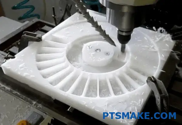
Is UHMWPE Machinable?
Have you ever tried machining UHMWPE only to find your tools gumming up or the material deforming under pressure? I’ve seen many engineers struggle with this unique plastic. Its exceptional properties make it valuable but also create significant machining challenges that can lead to project delays and quality issues.
Yes, UHMWPE (Ultra-High Molecular Weight Polyethylene) is machinable, but requires specific techniques. Its low friction coefficient and high molecular weight demand sharp tools, slower speeds, proper cooling, and specialized fixturing to achieve precision results.
I’ve worked with UHMWPE for many projects at PTSMAKE, and I can tell you it’s worth mastering its machining requirements. This material offers incredible wear resistance and impact strength that few other plastics can match. If you’re considering UHMWPE for your next project, you’ll want to understand the specific challenges and solutions for effectively machining this versatile material.
What Are The Disadvantages And Advantages Of UHMWPE?
Have you ever wondered why some materials seem perfect for one application yet problematic for another? UHMWPE presents this exact paradox – offering exceptional properties that make engineers excited while simultaneously creating challenges that can drive manufacturing teams crazy.
UHMWPE (Ultra-High Molecular Weight Polyethylene) combines remarkable wear resistance, impact strength, and chemical stability with low friction properties. However, it suffers from difficult machinability, poor heat resistance, susceptibility to UV degradation, and challenging bonding characteristics that limit certain applications.
Understanding UHMWPE’s Fundamental Properties
UHMWPE stands out among engineering plastics due to its unique molecular structure. With molecular chains that can be 10-100 times longer than standard polyethylene, this material achieves exceptional mechanical properties. The extraordinarily high molecular weight (typically 3.5-7.5 million g/mol) creates a material with interlocking chains that provide superior wear resistance and toughness.
In my 15+ years at PTSMAKE, I’ve seen firsthand how this material outperforms many metals and other plastics in high-wear applications. The molecular structure gives UHMWPE its characteristic combination of:
- Extremely low coefficient of friction (similar to PTFE)
- Outstanding abrasion resistance
- High impact strength, even at cryogenic temperatures
- Chemical resistance to most acids, bases, and solvents
- Self-lubricating properties
- Excellent fatigue resistance
Key Advantages of UHMWPE
Superior Wear Resistance and Durability
UHMWPE offers exceptional wear properties that make it ideal for components exposed to constant friction. This tribological performance1 translates to longevity in applications like:
- Conveyor components and chute liners
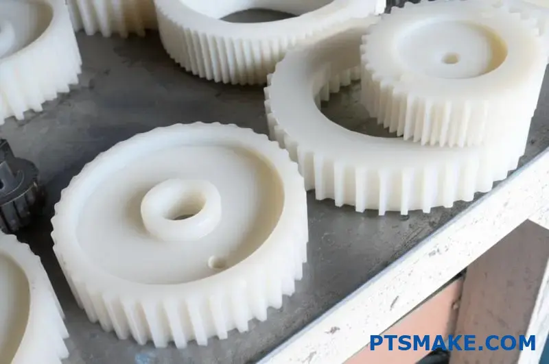
- Gears and sprockets
- Wear strips and guides
- Mining equipment components
When machining UHMWPE parts for high-wear environments, we consistently achieve 3-5 times longer service life compared to traditional materials like nylon or acetal.
Chemical Resistance
Another significant advantage is UHMWPE’s remarkable chemical stability. It resists:
- Acids and bases
- Organic solvents
- Alcohols and ketones
- Moisture and water
This makes it perfect for chemical processing equipment, storage tanks, and laboratory components where other materials would quickly degrade.
Exceptional Impact Strength
UHMWPE’s ability to absorb impact energy without cracking or breaking sets it apart from most engineering plastics. I’ve seen UHMWPE components withstand impacts that would shatter other materials, especially in low-temperature environments where many plastics become brittle.
Disadvantages of UHMWPE
Manufacturing Challenges
Despite its impressive properties, UHMWPE presents significant processing difficulties:
| Manufacturing Method | Challenges with UHMWPE |
|---|---|
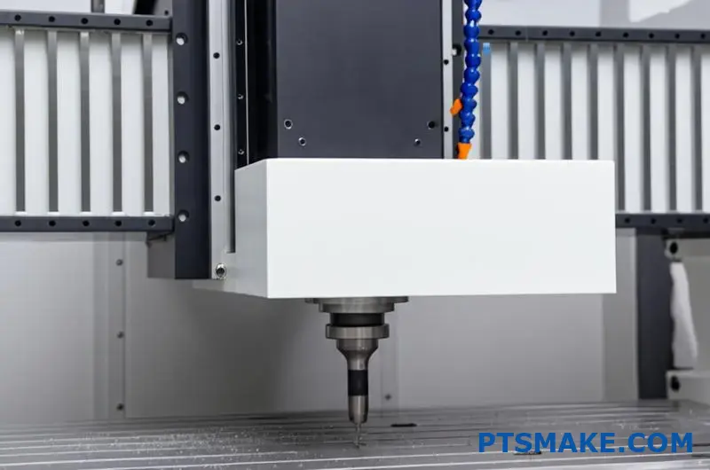
| CNC Machining | Tough to machine cleanly, tends to gum up tools, poor dimensional stability |
| Injection Molding | Nearly impossible due to extremely high melt viscosity |
| Extrusion | Requires specialized equipment and expertise |
| Compression Molding | Primary processing method but slow and limited to simple shapes |
At PTSMAKE, we’ve developed specialized machining protocols for UHMWPE to overcome these challenges, but they require precision equipment and experienced operators.
Limited Temperature Range
While UHMWPE performs exceptionally well at low temperatures, it suffers when exposed to heat:
- Begins to soften around 80°C (176°F)
- Shape distortion occurs at relatively low temperatures
- Cannot be used in high-temperature applications
This temperature limitation restricts its use in many industrial environments where heat exposure is common.
Poor UV Resistance
UHMWPE degrades when exposed to ultraviolet light, making it unsuitable for outdoor applications without additives or protective coatings. The material can become brittle and develop fine surface cracks after prolonged UV exposure.
Bonding and Joining Difficulties
The same properties that make UHMWPE chemically resistant also make it extremely difficult to bond:
- Conventional adhesives don’t adhere well
- Cannot be solvent welded like other plastics
- Requires special surface treatments for effective bonding
- Mechanical fastening is often the only reliable joining method
Cost Considerations
While not the most expensive engineering plastic, UHMWPE comes at a premium compared to standard plastics. This cost difference is justified when the material’s performance advantages align with application requirements, but can be prohibitive for projects where its unique properties aren’t essential.
Balancing Advantages and Disadvantages
Choosing UHMWPE requires careful consideration of both its strengths and limitations. From my experience at PTSMAKE, the most successful applications leverage UHMWPE’s wear resistance, impact strength, and chemical stability while mitigating its processing challenges through proper design and manufacturing techniques.
For many clients, the extended service life and reduced maintenance costs ultimately justify the higher initial investment in UHMWPE components. However, applications requiring heat resistance, UV stability, or complex joining methods may benefit from alternative materials or composite solutions.
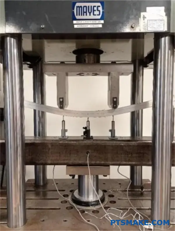
How Flexible Is UHMW?
Ever wondered if that tough UHMW plastic could bend without breaking for your application? Many engineers face this dilemma when selecting materials for parts that need both durability and flexibility, often compromising one quality for another and ending up with components that fail prematurely.
UHMW (Ultra-High Molecular Weight Polyethylene) offers moderate flexibility with excellent memory properties. While not as flexible as rubber or elastomers, UHMW can flex under load and return to its original shape, making it ideal for applications requiring both impact resistance and some degree of bend without permanent deformation.
Understanding UHMW Flexibility Characteristics
UHMW polyethylene occupies a unique position in the spectrum of engineering plastics. Its long-chain molecular structure gives it a combination of rigidity and flexibility that few materials can match. This balance makes it particularly valuable for applications where some degree of flex is necessary, but outright elasticity would compromise functional requirements.
The flexibility of UHMW stems from its semi-crystalline structure. Unlike fully crystalline polymers that tend to be brittle, or completely amorphous polymers that can be too soft, UHMW has regions of both ordered (crystalline) and disordered (amorphous) molecular arrangements. This structural characteristic allows the material to flex under load while maintaining overall dimensional stability.
Measuring UHMW Flexibility
When discussing flexibility in engineering terms, we often refer to specific mechanical properties that can be measured and compared. For UHMW, these key properties include:
| Property | Typical Value Range | Comparison to Other Materials |
|---|---|---|
| Flexural Modulus | 0.7-1.5 GPa | Lower than nylon (2-3 GPa), much lower than aluminum (69 GPa) |
| Elongation at Break | 200-350% | Higher than acetal (25-75%), lower than TPEs (300-700%) |
| Flex Life | Excellent (10⁶+ cycles) | Superior to most rigid plastics, inferior to elastomers |
| Cold Temperature Flexibility | Maintains flexibility to -40°F | Better than most plastics, which become brittle at low temperatures |
In my years at PTSMAKE, I’ve found that these numerical values only tell part of the story. The real-world flexibility of UHMW becomes most apparent when designing parts that must absorb impact, accommodate slight misalignments, or provide vibration dampening properties.
UHMW Flexibility in Different Form Factors
The flexibility of UHMW varies significantly depending on its thickness and form factor. This is a critical consideration when designing parts that require specific flexibility characteristics.
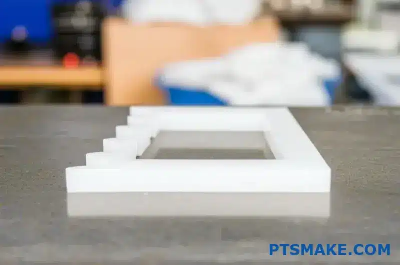
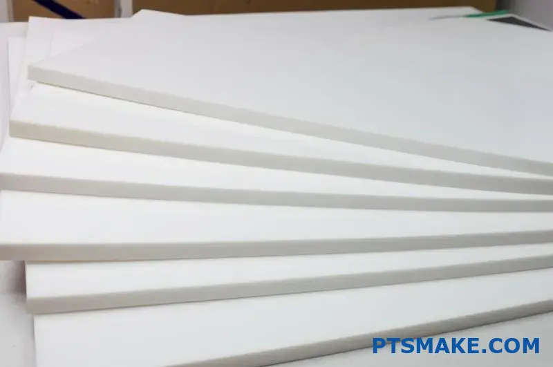
Sheet Thickness and Flexibility Correlation
UHMW sheets display a predictable relationship between thickness and flexibility:
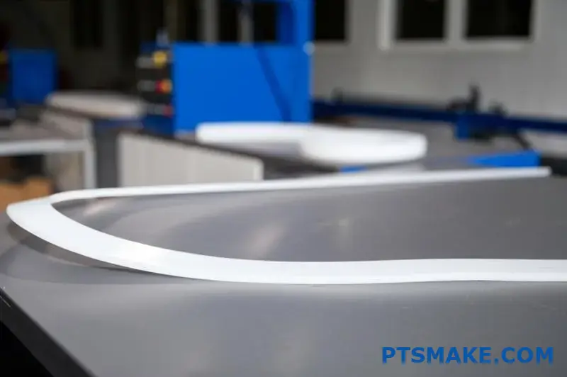
- Thin sheets (1/16" to 1/8"): Highly flexible, can be bent by hand
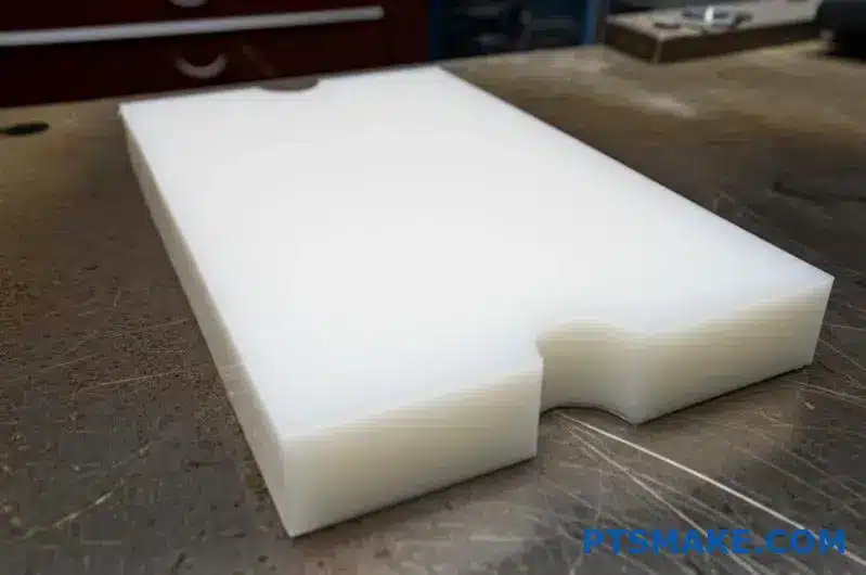
- Medium sheets (1/4" to 1/2"): Moderate flexibility, will bend under significant force
- Thick sheets (3/4" and above): Minimal flexibility, primarily rigid
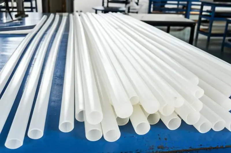
Rod and Tubular UHMW
UHMW in rod or tubular form presents unique flexibility characteristics. Solid rods are relatively rigid in shorter lengths but can exhibit significant flex when longer spans are unsupported. Tubular UHMW, which we occasionally produce for specialized applications, offers increased flexibility compared to solid profiles of similar outer diameter.
This property makes UHMW tubing particularly valuable for applications requiring both wear resistance and the ability to navigate bends and curves, such as material handling systems with curved paths.
Temperature Effects on UHMW Flexibility
One of the most remarkable aspects of UHMW’s flexibility is how it maintains performance across a wide temperature range. Unlike many plastics that become brittle in cold environments, UHMW retains its flexibility even at extremely low temperatures.
Cold Weather Performance
At temperatures as low as -40°F (-40°C), UHMW maintains most of its room temperature flexibility. This cryogenic resilience2 makes it an excellent choice for outdoor equipment, cold storage applications, and polar environments where other materials would become dangerously brittle.
I’ve worked with several clients in the food processing industry who specifically choose UHMW for freezer conveyor components precisely because it maintains its impact resistance and flexibility in these harsh conditions.
Heat Effects on Flexibility
While UHMW excels in cold environments, its flexibility characteristics change as temperatures rise:
- Below 80°F (27°C): Optimal flexibility with excellent memory
- 80-120°F (27-49°C): Increased flexibility, slightly reduced memory
- Above 120°F (49°C): Significantly increased flexibility, reduced structural integrity
- Approaching 180°F (82°C): Begins to deform permanently, flexibility no longer a relevant property
Application-Specific Flexibility Considerations
The appropriate level of flexibility for UHMW depends entirely on the application requirements. At PTSMAKE, we help clients evaluate whether UHMW’s flexibility characteristics align with their specific needs.
Ideal Applications for UHMW’s Flexibility
UHMW’s moderate flexibility makes it particularly well-suited for:
- Impact absorption components (bumpers, guards, wear pads)
- Material handling surfaces requiring slight give (chutes, liners)
- Parts spanning gaps that experience occasional loading
- Components that need to accommodate thermal expansion/contraction
- Applications where vibration dampening is beneficial
When UHMW Flexibility May Be Insufficient
For applications requiring extreme flexibility or elasticity, UHMW may not be the optimal choice:
- Highly flexible seals or gaskets (elastomers typically better)
- Applications requiring repeated extreme bending (>90° angles)
- Components that must stretch significantly (elastomers preferred)
- Parts requiring progressive resistance (rubber compounds better)
Enhancing or Controlling UHMW Flexibility
Through careful engineering and material selection, we can influence the flexibility characteristics of UHMW components to better match application requirements.
UHMW is available in several formulations that offer modified flexibility properties:
- Standard UHMW: Baseline flexibility
- UHMW with additives (silicone, etc.): Slightly increased flexibility
- Cross-linked UHMW: Reduced flexibility, increased heat resistance
- Fiber-reinforced UHMW: Significantly reduced flexibility, increased rigidity
Design features can also be incorporated to create controlled flexibility in otherwise rigid UHMW structures. These include thinned sections, living hinges, accordion patterns, and strategic void areas that allow for predictable flex patterns while maintaining overall structural integrity.
Is UHMW Better Than HDPE For Machinability?
Have you struggled with choosing between UHMW and HDPE for your machining projects? Many engineers face this dilemma when balancing material properties against manufacturing feasibility, often wondering if the premium price of UHMW translates to better machinability or if they’re just making their lives unnecessarily complicated.
When comparing machinability, standard HDPE is generally easier to machine than UHMW polyethylene. HDPE produces cleaner cuts, better finishes, and maintains tighter tolerances with less tool wear. However, UHMW offers superior end-product performance in wear applications despite being more challenging to machine.
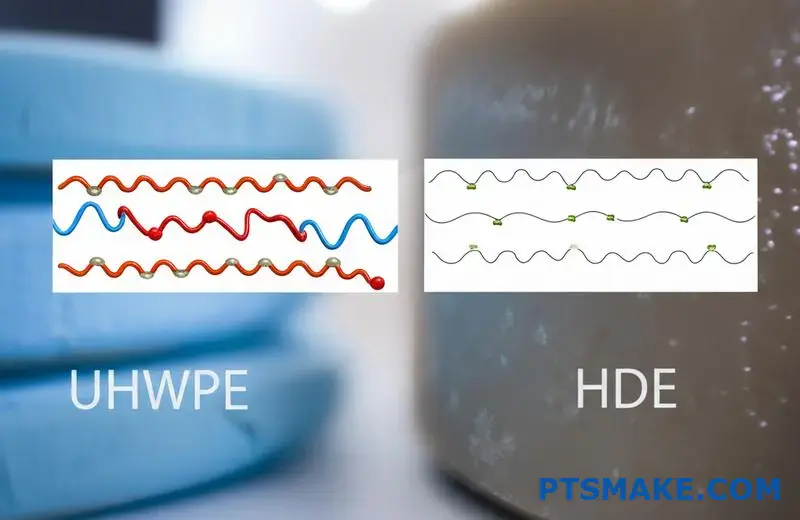
Comparing UHMW and HDPE Molecular Structures
The fundamental difference between UHMW and HDPE begins at the molecular level, which directly impacts machinability. UHMW (Ultra-High Molecular Weight Polyethylene) has extremely long polymer chains with molecular weights typically between 3.5-7.5 million g/mol, while standard HDPE (High-Density Polyethylene) has shorter chains with molecular weights around 0.05-0.25 million g/mol.
These molecular differences create distinct material characteristics that affect machining:
Molecular Chain Length Effects on Machining
UHMW’s exceptionally long molecular chains give it outstanding wear resistance and impact strength but create challenges during the machining process. The long, entangled chains behave somewhat like tangled fishing line when cut, making clean separation difficult.
In contrast, HDPE’s shorter molecular chains allow for cleaner cutting action. The material separates more predictably under the cutting tool, resulting in less gumming and smoother finished surfaces.
Tool Engagement and Chip Formation
HDPE Machining Characteristics
When machining HDPE, chips form and break away more readily from the workpiece. This characteristic results in:
- Reduced heat generation during cutting
- Less tool loading and gumming
- More predictable material removal rates
- Better surface finish directly off the machine
From my experience at PTSMAKE, HDPE generally allows for faster cutting speeds and higher feed rates compared to UHMW, making it more economical for high-volume production runs.
UHMW Machining Challenges
UHMW presents several distinctive challenges during machining operations:
- Tendency to gum up cutting tools
- Higher friction and heat generation
- Material "push-back" against cutting edges
- Greater difficulty maintaining tight tolerances
- More pronounced tool wear
These issues stem from UHMW’s remarkably high abrasion resistance and self-lubricating properties – the very characteristics that make it valuable in end applications often make it troublesome during manufacturing.
Tolerance Control Comparison
Maintaining dimensional accuracy represents one of the most significant differences between machining these materials.
| Aspect | HDPE | UHMW |
|---|---|---|
| Dimensional Stability | Good | Fair to Poor |
| Tight Tolerance Capability | ±0.003" relatively easy | ±0.005" challenging |
| Warping Tendency | Low | Moderate |
| Heat Sensitivity During Machining | Lower | Higher |
| Post-Machining Dimensional Change | Minimal | More pronounced |
HDPE generally exhibits better dimensional stability during and after machining. UHMW has a greater tendency to "relax" after machining as internal stresses redistribute, sometimes resulting in slight dimensional changes hours or even days after completing the machining operation.
Surface Finish Capabilities
The quality of surface finish achievable is another important consideration when choosing between these materials for machined parts.
HDPE Surface Finish
HDPE typically produces better surface finishes with standard machining practices:
- Smoother as-cut surfaces
- Less "fuzziness" along edges
- Better thread definition
- More consistent appearance
- Fewer visual defects
Most conventional machining techniques work well with HDPE, producing predictable and aesthetically pleasing results with minimal secondary operations.
UHMW Surface Finish
UHMW often requires additional considerations to achieve comparable surface quality:
- May exhibit "stringiness" along cut edges
- Requires sharper tools to minimize surface roughness
- Often needs slower cutting speeds for better finish
- Sometimes requires secondary finishing operations
- Can develop surface imperfections from heat during machining
At PTSMAKE, we’ve developed specialized techniques for machining UHMW to overcome these issues, including cryogenic cooling approaches for particularly demanding applications.
Tool Selection and Wear Considerations
The choice of cutting tools significantly impacts success when machining either material, but the differences are pronounced.
Tool Requirements for HDPE
HDPE is relatively forgiving regarding tool selection:
- Standard HSS tools perform adequately
- Conventional geometries work well
- Normal rake and clearance angles are effective
- Tool life is generally good
- Less specialized tooling required
Tool Requirements for UHMW
UHMW demands more specific tooling considerations:
- Extremely sharp cutting edges required
- Higher rake angles beneficial
- Polished tool surfaces reduce friction
- PCD (polycrystalline diamond) tools sometimes necessary for production runs
- More frequent tool replacement or resharpening needed
The abrasive nature of UHMW, despite its seemingly soft character, accelerates tool wear significantly compared to HDPE. This increases machining costs for UHMW components beyond just the higher material cost.
Machining Parameters Comparison
The optimal machining parameters differ significantly between these materials, with HDPE generally allowing for more aggressive cutting conditions.
| Parameter | HDPE | UHMW |
|---|---|---|
| Cutting Speed | Faster (500-1000 SFM) | Slower (300-700 SFM) |
| Feed Rate | Higher | Lower |
| Depth of Cut | More aggressive possible | More conservative recommended |
| Cooling Requirements | Minimal | More critical |
| Tool Engagement | Can be higher | Should be limited |
These differences translate directly to production efficiency. In our shop, we can typically machine HDPE components 20-30% faster than equivalent UHMW parts, which significantly impacts production costs.
Thermal Management During Machining
Heat management represents a crucial difference when machining these materials.
Heat Dissipation in HDPE
HDPE conducts heat better than UHMW and has a slightly higher melting point, making it more forgiving during machining operations:
- Less prone to localized melting
- Better heat dissipation from cutting zone
- Lower friction coefficient during cutting
- Less tendency to adhere to tools when heated
- More tolerance for aggressive machining parameters
Heat Challenges with UHMW
UHMW’s poor thermal conductivity creates significant challenges:
- Heat concentrates at the cutting interface
- Material can readily gall to cutting tools
- More likely to experience thermal deformation
- Requires more conservative cutting approaches
- Often needs additional cooling strategies
The thermal challenges with UHMW often necessitate reduced material removal rates and increased cycle times, further impacting the economic aspects of machining this material.
Cost-Benefit Analysis for Machining Applications
When deciding between these materials, several factors beyond pure machinability must be considered:
- Raw material cost (UHMW typically 2-3× higher than HDPE)
- Machining time (20-30% longer for UHMW)
- Tool consumption (higher for UHMW)
- End-use requirements (wear resistance, impact strength, etc.)
- Production volume and timeline
For applications where the superior performance characteristics of UHMW aren’t critical, HDPE often represents the more economical choice, offering better machinability at a lower material cost. However, in applications where wear resistance, impact strength, or chemical resistance are paramount, the machining challenges of UHMW may be worthwhile despite the higher processing costs.
Optimizing Machining Approaches for Both Materials
Based on my experience at PTSMAKE, I’ve found several strategies effective for improving results when machining either material:
For HDPE:
- Use sharp, properly designed plastic-cutting tools
- Maintain moderate speeds and feeds
- Ensure adequate chip evacuation
- Support thin-walled sections during machining
- Allow for slight material spring-back in precision applications
For UHMW:
- Use extremely sharp cutting tools with polished surfaces
- Employ cooler cutting speeds and conservative feed rates
- Provide abundant cooling, especially for deep cuts
- Design fixtures to minimize workpiece deflection
- Allow extra material for final finishing passes
Both materials benefit from proper workholding strategies that minimize clamping deformation while providing adequate support throughout the cutting operation.
What Is The Difference Between UHMW And HDPE Machining?
Ever wondered why two similar-looking polyethylenes require completely different machining approaches? Many engineers mistakenly treat UHMW and HDPE as interchangeable in their CNC programs, only to discover ruined parts, damaged tools, and missed deadlines when the machines start running.
The key difference between UHMW and HDPE machining lies in their molecular structures. HDPE machines more predictably with better surface finish and dimensional stability, while UHMW’s extremely long polymer chains cause material gumming, tool loading, and require slower speeds with sharper tools to achieve comparable results.
Fundamental Material Differences Affecting Machinability
When comparing UHMW (Ultra-High Molecular Weight Polyethylene) and HDPE (High-Density Polyethylene), we’re essentially looking at relatives in the polyethylene family with dramatically different characteristics. These differences stem primarily from their molecular structures and directly impact how they respond to machining operations.
Molecular Weight Comparison
The most significant distinction between these materials is their molecular weight:
| Material | Molecular Weight (g/mol) | Chain Length | Crystallinity |
|---|---|---|---|
| HDPE | 200,000-500,000 | Moderate | 70-80% |
| UHMW | 3,000,000-6,000,000 | Extremely long | 45-55% |
This substantial difference in molecular weight creates unique machining challenges. HDPE’s moderate chain length allows the material to cut cleanly, with chips breaking away predictably during machining operations. In contrast, UHMW’s extremely long molecular chains become entangled, causing the material to resist clean cutting and instead "smear" or deform when machined with standard techniques.
Thermal Behavior During Machining
Temperature management represents another crucial difference when machining these materials:
- HDPE: Better thermal conductivity allows heat to dissipate more effectively during machining, reducing the risk of localized melting or deformation.
- UHMW: Poor thermal conductivity causes heat to concentrate at the cutting interface, potentially leading to material gumming, tool adhesion, and dimensional inaccuracies.
At PTSMAKE, we’ve developed specialized cooling techniques for UHMW machining that help manage these thermal challenges, particularly for precision components with tight tolerances.
Tool Engagement and Cutting Dynamics
Chip Formation Differences
The way each material forms chips during machining operations reveals much about their machinability:
- HDPE Chip Formation: Forms discrete chips that break cleanly from the workpiece, allowing for efficient material removal with minimal heat generation.
- UHMW Chip Formation: Tends to form continuous, stringy chips that can wrap around tools, causing interruptions and potential damage to both the tool and workpiece.
In our machining centers, we’ve installed specialized chip management systems specifically for handling UHMW’s challenging chip characteristics.
Cutting Forces and Tool Pressure
The resistance to cutting also differs significantly between these materials:
- HDPE: Requires moderate cutting forces, responds predictably to tool pressure.
- UHMW: Exhibits higher resistance to cutting, sometimes "pushes back" against the cutting edge due to its elasticity and toughness.
Surface Finish and Quality Considerations
One of the most noticeable differences when machining these materials is the quality of surface finish achievable with standard techniques.
Surface Finish Capabilities
| Aspect | HDPE | UHMW |
|---|---|---|
| As-Machined Finish | Smooth, consistent | Often rough, may show tooling marks |
| Edge Quality | Clean, well-defined | Can be fuzzy or have hanging strands |
| Surface Uniformity | Highly uniform | May show variations in texture |
| Polishability | Good | Limited |
HDPE generally produces superior surface finishes right off the machine, while UHMW often requires additional finishing operations to achieve comparable results. This difference impacts both the aesthetics and functional characteristics of the finished components.
Dimensional Stability During and After Machining
Another critical difference lies in how well these materials maintain their dimensions:
- HDPE: Exhibits good dimensional stability during machining, with minimal post-machining movement.
- UHMW: Tends to "relax" after machining as internal stresses redistribute, sometimes resulting in slight dimensional changes hours or even days after machining.
This characteristic of UHMW requires special consideration in design and machining planning, often necessitating allowances for post-machining dimensional shifts.
Tool Selection and Optimization
The choice of cutting tools significantly impacts success when machining either material, but the requirements differ considerably.
Cutting Tool Geometry
For optimal results with each material:
- HDPE: Standard plastic-cutting geometries work well, with moderate rake angles and conventional clearances.
- UHMW: Benefits from specialized tool geometries with higher rake angles, polished cutting surfaces, and extremely sharp cutting edges.
Tool Wear Patterns
The way tools wear when cutting these materials also differs:
- HDPE: Causes moderate, predictable tool wear primarily through abrasion.
- UHMW: Accelerates tool wear through a combination of abrasion and adhesion mechanisms, often creating uneven wear patterns that can affect part quality.
At PTSMAKE, we’ve found that investing in premium tooling for UHMW machining provides better overall economy than using standard tools that require frequent replacement or resharpening.
Optimizing Machining Parameters
The optimal machining parameters vary significantly between these materials, with HDPE generally allowing for more aggressive cutting conditions.
Speed and Feed Recommendations
| Parameter | HDPE | UHMW |
|---|---|---|
| Cutting Speed | 500-1000 SFM | 300-600 SFM |
| Feed Rate | 0.005-0.020 in/tooth | 0.003-0.012 in/tooth |
| Depth of Cut | Can be aggressive | Should be conservative |
| Tool Rigidity | Standard importance | Critical importance |
These differences directly impact production efficiency and costs. In our machining operations, HDPE components can typically be completed 25-35% faster than equivalent UHMW parts.
Special Considerations for Complex Geometries
When machining intricate features, the differences between these materials become even more pronounced:
Thin Walls and Delicate Features
- HDPE: Maintains better stability during machining of thin walls, allowing for thinner sections.
- UHMW: Requires more substantial minimum wall thicknesses due to its flexibility and machining characteristics.
Thread Machining
Cutting threads presents particular challenges:
- HDPE: Forms clean, well-defined threads with standard threading tools and techniques.
- UHMW: Thread quality is often compromised by material elasticity3, requiring specialized approaches for acceptable results.
Deep Hole Drilling
When creating deep holes:
- HDPE: Allows for standard drilling techniques with good chip evacuation.
- UHMW: Requires specialized "peck" drilling cycles and enhanced cooling to prevent chip packing and hole deformation.
Cost-Effectiveness Analysis
When deciding between these materials for machined components, several factors beyond pure machinability must be considered:
- Material Cost: UHMW typically costs 2-3 times more than HDPE per volume.
- Machining Time: UHMW components take 25-35% longer to machine on average.
- Tool Consumption: Tool costs for UHMW machining are significantly higher due to increased wear and specialized requirements.
- Scrap Rate: The challenging nature of UHMW machining often results in higher rejection rates, particularly for complex parts.
However, these higher production costs must be balanced against the superior performance characteristics of UHMW in demanding applications. For components subject to high wear, impact, or abrasion, the extended service life of UHMW often justifies the additional machining challenges and costs.
Practical Recommendations Based on Application Requirements
Based on my extensive experience at PTSMAKE with both materials, here are my recommendations for material selection based on application requirements:
Choose HDPE when:
- Dimensional precision is critical
- Complex geometries with fine details are required
- Production cost is a primary concern
- Moderate wear resistance is sufficient
- High volume production efficiency is important
Choose UHMW when:
- Extreme wear resistance is needed
- Impact strength is critical
- Chemical resistance is essential
- Low friction properties are required
- Extended component lifespan justifies higher production costs
Understanding these fundamental differences between UHMW and HDPE machining can help engineers make informed material selections that balance manufacturability, cost, and performance requirements for their specific applications.
Can You Laser Cut UHMWPE?
Have you ever faced the challenge of cutting UHMWPE for a project, wondering if laser cutting might offer a clean, precise solution? Many engineers and designers struggle with this material’s unique properties, often finding themselves frustrated when traditional cutting methods produce unsatisfactory results or when experimenting with laser technology yields disappointing outcomes.
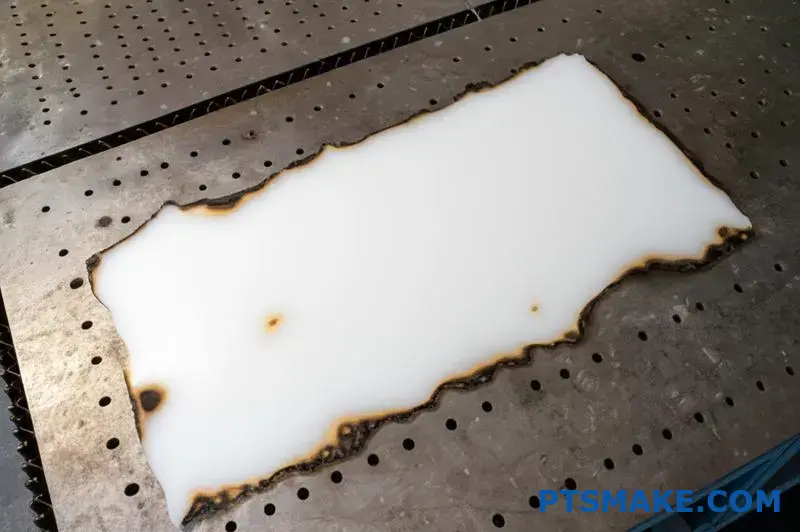
No, conventional CO2 and fiber lasers cannot effectively cut UHMWPE (Ultra-High Molecular Weight Polyethylene). The material’s high reflectivity, low melting point, and thermal properties cause it to melt rather than vaporize, resulting in charred edges, poor cut quality, and potential equipment damage. Mechanical cutting methods are strongly recommended instead.
The Challenges of Laser Cutting UHMWPE
When it comes to fabricating UHMWPE components, laser cutting presents significant challenges that make it generally impractical for this specific material. Understanding why requires looking at both the material properties of UHMWPE and the physics of laser cutting.
Why UHMWPE Resists Laser Cutting
UHMWPE has several inherent properties that make it particularly problematic for laser cutting:
High Reflectivity: UHMWPE reflects a significant portion of laser energy rather than absorbing it, especially when using CO2 lasers. This reflection reduces cutting efficiency and can potentially damage laser equipment by redirecting the beam back into the optics.
Low Melting Point: UHMWPE begins to soften at around 80°C and melts at approximately 135-138°C, which is relatively low compared to other engineering plastics. This low melting point means the material tends to melt rather than cleanly vaporize during laser cutting.
Thermal Behavior: When heated, UHMWPE doesn’t undergo a clean phase transition from solid to gas (sublimation) that would enable clean laser cutting. Instead, it passes through a molten state that results in poor edge quality.
High Thermal Expansion: The material expands significantly when heated, causing dimensional instability during cutting that makes precision difficult to achieve.
What Happens When You Attempt Laser Cutting
When laser cutting is attempted on UHMWPE, several undesirable outcomes typically occur:
| Issue | Cause | Result |
|---|---|---|
| Melting/Charring | Low melting point | Rough, discolored edges with poor dimensional accuracy |
| Incomplete Cutting | Beam reflection | Inability to penetrate through thicker sections |
| Warping | Thermal expansion | Dimensional distortion of the workpiece |
| Material Recombination | Molten material flow-back | Cut lines that reseal behind the beam |
| Smoke/Fumes | Thermal decomposition | Potentially hazardous emissions requiring ventilation |
In my experience at PTSMAKE, we’ve seen numerous cases where clients attempted laser cutting of UHMWPE before coming to us, invariably resulting in unsatisfactory parts with poor edge quality, dimensional inaccuracy, and sometimes heat-affected zones that compromised the material’s properties.
Alternative Cutting Methods for UHMWPE
Since laser cutting is generally not suitable for UHMWPE, several alternative cutting methods offer much better results:
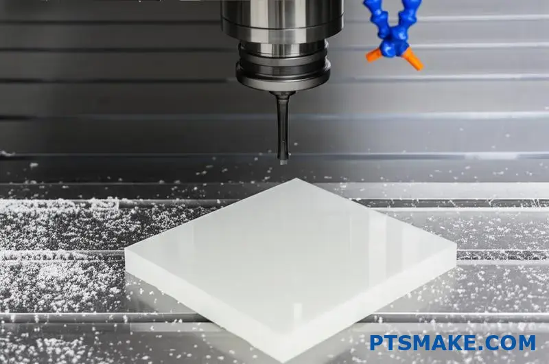
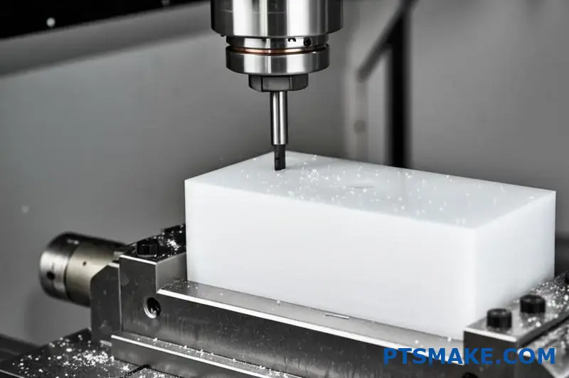
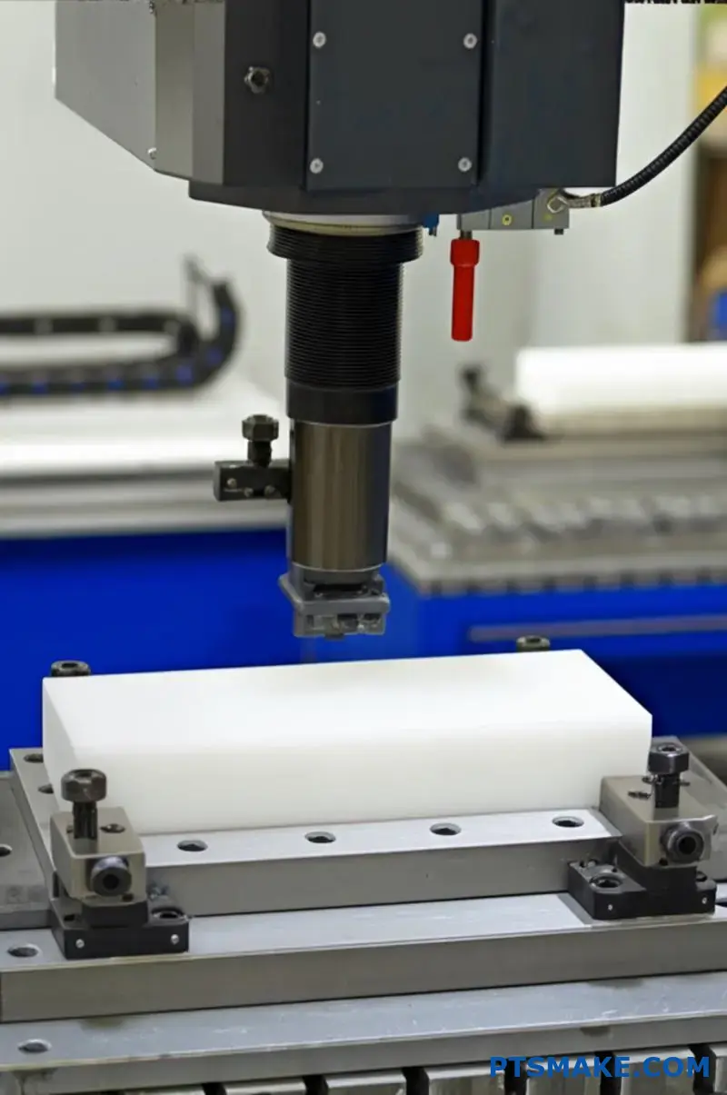
CNC Machining
CNC machining represents the gold standard for producing precision UHMWPE components. While the material can be challenging to machine due to its toughness and elasticity, proper techniques yield excellent results:
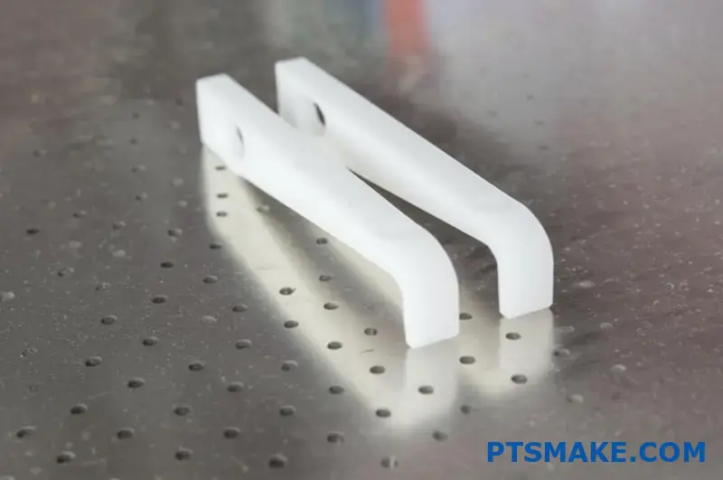
- Advantages: Precise dimensions, excellent edge quality, ability to create complex geometries
- Considerations: Requires sharp cutting tools, proper cooling, and appropriate feed rates
At PTSMAKE, we’ve developed specialized CNC protocols specifically for UHMWPE that minimize material deformation and tool gumming while maintaining tight tolerances.
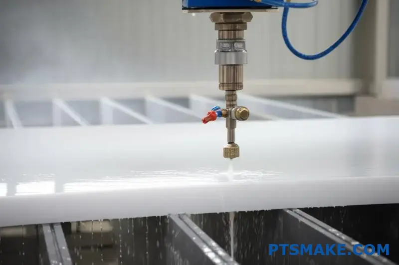
Waterjet Cutting
Waterjet cutting offers a compelling alternative for UHMWPE sheets and plates:
- Advantages: No heat affected zone, clean edges, ability to cut thick sections
- Considerations: Lower precision than CNC for complex features, potential for slight edge taper
The cold-cutting nature of waterjet technology prevents the thermal issues that make laser cutting problematic, making it particularly suitable for straight cuts or simple geometries in UHMWPE.
Band Saw Cutting
For straight cuts and rough dimensioning, industrial band saws can be effective:
- Advantages: Fast, economical, minimal material waste
- Considerations: Limited to straight cuts, requires finishing operations for precision edges
Die Cutting
For high-volume production of thin UHMWPE sheets:
- Advantages: Fast production rates, consistent part dimensions
- Considerations: High initial tooling cost, limited to simpler geometries
Optimizing Mechanical Cutting of UHMWPE
While laser cutting isn’t viable, we can still achieve excellent results with mechanical cutting methods by following these best practices:
Tool Selection for UHMWPE
The right cutting tools make a significant difference when working with UHMWPE:
- For CNC Milling: Use sharp, polished cutting tools with high rake angles
- For Sawing: Choose fine-tooth blades with aggressive rake angles
- For Drilling: Sharp drill bits with proper point geometry to prevent material pushing
Cooling and Lubrication
Proper cooling is essential when cutting UHMWPE:
- Flood Cooling: Helps prevent heat buildup that could cause dimensional issues
- Compressed Air: Can be sufficient for lighter cutting operations
- Avoiding Overheating: Critical to maintain material properties and dimensional stability
Fixturing Considerations
UHMWPE’s flexibility requires proper workpiece support:
- Rigid Support: Prevents material deflection during cutting
- Vacuum Tables: Effective for holding sheet material without distortion
- Custom Fixtures: May be necessary for complex geometries
When Lasers Might Still Be Considered
While conventional CO2 and fiber lasers are generally unsuitable, there are a few specialized scenarios where laser technology might still be considered for UHMWPE:
UV Lasers for Surface Marking
Ultraviolet lasers can sometimes be used for surface marking without cutting:
- Advantages: Can create permanent markings without penetrating deeply
- Considerations: Limited to surface effects, not suitable for cutting
Experimental Laser Technologies
Research into specialized laser systems continues:
- Femtosecond Lasers: Ultra-short pulse lasers might theoretically overcome some UHMWPE challenges
- Custom Wavelengths: Lasers optimized for UHMWPE’s absorption characteristics
- Practical Limitations: Such systems remain extremely expensive and impractical for most applications
Cost-Benefit Analysis of Cutting Methods
When evaluating options for fabricating UHMWPE components, consider these factors:
| Cutting Method | Initial Setup Cost | Per-Part Cost | Edge Quality | Dimensional Accuracy | Throughput |
|---|---|---|---|---|---|
| CNC Machining | Medium-High | Medium | Excellent | Excellent | Medium |
| Waterjet | Medium | Medium-High | Very Good | Good | Medium-High |
| Band Saw | Low | Low | Poor-Fair | Fair | High |
| Die Cutting | Very High | Very Low | Good | Good | Very High |
The most appropriate method depends on your specific application requirements, production volume, and quality needs. For precision components where material properties must be preserved, CNC machining typically provides the best overall value despite its medium cost profile.
Real-World Applications and Considerations
In my years at PTSMAKE, I’ve seen UHMWPE used in numerous applications where its unique properties are essential:
- Wear Components: Bushings, bearings, wear pads
- Food Processing Equipment: Cutting boards, guide rails
- Medical Devices: Implantable components
- Industrial Liners: Chute linings, hopper liners
For these applications, maintaining material integrity during fabrication is crucial. The heat generated during laser cutting would compromise the very properties that make UHMWPE valuable in the first place, such as its wear resistance and molecular cohesion4.
While laser cutting might seem appealing for its speed and precision with other materials, the mechanical cutting methods discussed above consistently deliver superior results for UHMWPE components, preserving the material’s exceptional performance characteristics while achieving the necessary dimensional accuracy.
What Are The Best Practices For CNC Machining UHMWPE?
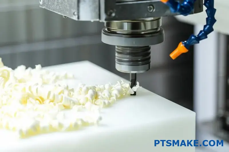
Have you struggled with gummy tools, poor surface finishes, or dimensional inaccuracies when machining UHMWPE? Many manufacturers find themselves fighting against this uniquely challenging material, watching cutting tools become coated with melted plastic while dimensional tolerances slip further out of reach.
Successful CNC machining of UHMWPE requires sharp cutting tools with positive rake angles, slower spindle speeds to prevent heat buildup, adequate cooling, rigid workholding, and proper feed rates. These practices minimize material gumming, maintain dimensional stability, and produce clean cuts in this challenging but valuable engineering plastic.
Understanding UHMWPE’s Unique Machining Challenges
Ultra-High Molecular Weight Polyethylene presents distinctive challenges during CNC machining operations due to its molecular structure and physical properties. With extremely long polymer chains (typically 3.5-7.5 million g/mol), UHMWPE delivers exceptional wear resistance and impact strength but creates significant machining difficulties.
Material Properties Affecting Machinability
To effectively machine UHMWPE, it’s essential to understand how its unique properties impact the cutting process:
High Molecular Weight: The extremely long molecular chains resist clean cutting and tend to smear rather than form chips.
Low Thermal Conductivity: UHMWPE dissipates heat poorly, causing temperature buildup at the cutting interface.
Low Melting Point: The material begins to soften at around 80°C (176°F) and melts at approximately 130-136°C (266-277°F).
High Abrasion Resistance: While beneficial for end-use applications, this property accelerates tool wear during machining.
Viscoelastic Behavior: UHMWPE exhibits both viscous and elastic properties under load, causing dimensional challenges.
These properties combine to create a material that resists conventional machining approaches. At PTSMAKE, we’ve developed specialized techniques to overcome these challenges and consistently produce high-precision UHMWPE components.
Optimizing Cutting Tools for UHMWPE
The selection of appropriate cutting tools is perhaps the most critical factor in successful UHMWPE machining.
Tool Material Selection
My experience has shown these tool materials perform best with UHMWPE:
| Tool Material | Performance | Best Applications |
|---|---|---|
| Carbide | Good all-around performance | General milling and turning |
| PCD (Polycrystalline Diamond) | Excellent edge retention, premium choice | Production runs, precision finishing |
| High-Speed Steel (HSS) | Acceptable for limited use | Prototype work, simple operations |
While standard carbide tools can work for basic operations, I’ve found that premium-grade carbide or PCD tools provide significantly better results for production work. The initial investment in higher-quality tooling pays dividends through extended tool life and superior surface finish.
Critical Tool Geometry Features
Tool geometry significantly impacts UHMWPE machining success:
- Rake Angle: High positive rake angles (10-20°) reduce cutting forces and heat generation
- Relief Angle: Generous relief angles (10-15°) prevent rubbing and material buildup
- Cutting Edge: Extremely sharp cutting edges minimize material pushing and deformation
- Surface Finish: Polished tool surfaces reduce friction and prevent material adhesion
At PTSMAKE, we often use specialized tooling with geometries specifically designed for thermoplastics. These tools feature highly polished surfaces and extremely sharp cutting edges that minimize material smearing and produce cleaner cuts.
Optimal Machining Parameters
Proper cutting parameters are essential for successful UHMWPE machining.
Speed and Feed Recommendations
The tendency of UHMWPE to heat up during machining necessitates conservative cutting parameters:
| Operation | Speed Recommendation | Feed Recommendation |
|---|---|---|
| Milling | 300-700 SFM (surface feet per minute) | 0.003-0.010 inches per tooth |
| Turning | 300-600 SFM | 0.004-0.012 inches per revolution |
| Drilling | 200-400 SFM | 0.005-0.015 inches per revolution |
These parameters should be adjusted based on machine rigidity, tool condition, and specific part requirements. I’ve found that slower cutting speeds generally produce better results with UHMWPE, even though this increases cycle time.
Depth of Cut Considerations
When machining UHMWPE, the depth of cut significantly impacts both heat generation and part quality:
- Roughing Operations: Moderate depths of cut (0.050-0.100") with appropriate feed rates
- Finishing Operations: Light depths of cut (0.010-0.030") with higher feed rates relatively to depth
- Full-Slotting: Avoid when possible; if necessary, reduce speed by 30-40%
The key principle is to balance material removal rate against heat generation. Removing too much material at once generates excessive heat, while taking cuts that are too light can cause rubbing rather than clean cutting.
Effective Cooling Strategies
Proper cooling is critical when machining UHMWPE due to its poor thermal conductivity and low melting point.
Cooling Method Comparison
| Cooling Method | Effectiveness | Best Applications |
|---|---|---|
| Flood Coolant | Very Good | General machining, deep pockets |
| Compressed Air | Good | Light cuts, thin sections |
| Cryogenic Cooling | Excellent | Precision components, difficult features |
| Mist Cooling | Fair | Simple profiling, light duty work |
In my experience at PTSMAKE, flood coolant delivers the most consistent results for most UHMWPE applications. The continuous flow removes heat effectively and helps flush chips away from the cutting zone.
For particularly challenging applications, we sometimes employ cryogenic cooling techniques using liquid nitrogen or CO₂. This approach dramatically reduces thermal issues but requires specialized equipment and safety protocols.
Workholding and Fixturing Best Practices
Proper workholding is essential when machining UHMWPE due to its flexibility and tendency to deform under pressure.
Effective Workholding Strategies
- Vacuum Tables: Ideal for sheet material; provides even, distributed holding force
- Custom Fixtures: Design fixtures with broad contact areas to distribute clamping forces
- Low Clamping Pressure: Use just enough force to secure the workpiece without deformation
- Support Material: Provide complete support under thin sections to prevent deflection
- Uniform Support: Ensure even support across the entire workpiece
When designing fixtures for UHMWPE machining, remember that the material has a much lower modulus of elasticity than metals. Fixtures that would work well for aluminum or steel may cause significant workpiece deflection with UHMWPE.
Chip Evacuation and Management
Effective chip removal is particularly important when machining UHMWPE.
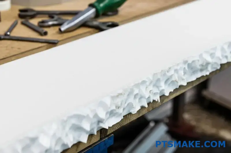
Chip Formation Challenges
Unlike metals that form discrete chips, UHMWPE often produces long, stringy chips that can wrap around tools or fall back into the cutting path. These chips can:
- Recut and damage the workpiece surface
- Wrap around the spindle or tool
- Interfere with coolant delivery
- Cause heat buildup if not removed
To manage these challenges, implement these strategies:
- Use high-pressure coolant directed at the cutting zone
- Program regular tool retractions to break chips
- Consider chip-breaking tool geometries when available
- Incorporate air blasts in conjunction with coolant
At PTSMAKE, we’ve installed specialized chip evacuation systems on our CNC machines dedicated to polymer machining5 to ensure consistent chip removal and prevent the quality issues associated with chip wrapping or recutting.
Dimensional Considerations and Tolerancing
UHMWPE’s viscoelastic properties create unique challenges for maintaining tight tolerances.
Material Behavior Affecting Dimensions
Several factors influence dimensional accuracy when machining UHMWPE:
- Thermal Expansion: UHMWPE has a high coefficient of thermal expansion
- Memory Effect: The material tends to "remember" its original shape
- Stress Relaxation: Internal stresses can cause dimensional changes after machining
- Moisture Absorption: Though minimal, can affect dimensions in precise applications
Practical Tolerance Guidelines
Based on my experience at PTSMAKE, these are practical tolerance capabilities for UHMWPE:
| Feature Type | Practical Tolerance | Challenging but Possible |
|---|---|---|
| External Dimensions | ±0.005" | ±0.002" |
| Hole Diameters | ±0.003" | ±0.001" |
| Positional Tolerance | ±0.007" | ±0.003" |
| Surface Finish | 125 μin Ra | 32 μin Ra |
To achieve the tighter tolerances in the "challenging but possible" column, specialized techniques, premium tooling, and potentially secondary operations may be required.
Surface Finish Optimization
Achieving excellent surface finishes on UHMWPE requires specific techniques.
Strategies for Improved Surface Quality
- Tool Selection: Use extremely sharp, polished cutting tools
- High Surface Speeds: For finishing passes only, slightly higher speeds can improve surface finish
- Light Finishing Passes: Take very light cuts (0.005-0.010") for final dimensions
- Tool Path Strategy: Climb milling generally produces better finishes than conventional milling
- Rigidity: Minimize tool extension and ensure rigid workholding
For applications requiring exceptional surface finish, consider these additional steps:
- Allow machined parts to "rest" for 24 hours before final finishing passes
- Use diamond-polished cutting tools for final operations
- Consider secondary polishing operations for critical surfaces
Post-Machining Considerations
After machining UHMWPE components, several considerations ensure optimal part quality.
Stress Relief and Stabilization
UHMWPE parts may continue to change dimensions slightly after machining as internal stresses equalize. For precision applications, consider:
- Machining to near-final dimensions
- Allowing parts to stabilize for 24-48 hours
- Performing final light finishing cuts after stabilization
Cleaning and Inspection
UHMWPE’s low surface energy can make it difficult to clean:
- Use isopropyl alcohol or specialized plastic cleaners
- Avoid harsh solvents that may cause stress cracking
- Inspect for any embedded chips or debris
- Check for any heat-affected zones (typically visible as glossy areas)
Surface Treatment Options
For specific applications, surface treatments may enhance performance:
- Plasma Treatment: Improves adhesion for bonding or coating
- Corona Discharge: Increases surface energy for better wettability
- Mechanical Texturing: Creates controlled surface patterns for specific functions
Industry-Specific Applications and Considerations
Different industries have unique requirements for UHMWPE components that influence machining approaches.
Medical Industry
For medical applications, additional considerations include:
- Material Certification: Using only medical-grade UHMWPE with appropriate documentation
- Surface Finish: Extremely smooth finishes for implantable components
- Cleanliness: Machining in clean environments to prevent contamination
- Documentation: Maintaining complete traceability throughout the manufacturing process
At PTSMAKE, we maintain separate equipment and tooling for medical-grade materials to prevent cross-contamination and ensure compliance with regulatory requirements.
Industrial and Mechanical Applications
For wear components and mechanical applications:
- Dimensional Stability: Critical for bearing surfaces and moving parts
- Surface Finish: Optimized for specific friction requirements
- Edge Quality: Sharp, clean edges for scraper and guide applications
- Thickness Uniformity: Essential for even wear characteristics
These applications often benefit from UHMWPE’s exceptional wear resistance and low friction coefficient, making the additional machining challenges worthwhile.
Food Processing Equipment
For food-contact applications:
- Surface Texture: Non-porous surfaces to prevent bacterial growth
- Edge Rounding: Elimination of sharp corners that could harbor contaminants
- Material Purity: Using only FDA-compliant grades without additives
- Inspection: 100% visual inspection for any embedded foreign material
Through careful application of these best practices, CNC machining can transform challenging UHMWPE material into high-performance components that leverage its exceptional properties while maintaining precise dimensions and excellent surface quality.
How To Prevent Deformation During UHMWPE Machining?
Have you ever watched your carefully designed UHMWPE part warp before your eyes during machining? Many engineers face this frustrating challenge when working with this exceptional material, finding that conventional machining approaches leave them with distorted parts that fail quality inspections despite following seemingly correct procedures.
To prevent deformation during UHMWPE machining, use sharp cutting tools with positive rake angles, maintain low cutting temperatures, employ adequate workholding without excessive clamping pressure, utilize proper machining parameters with moderate feeds and speeds, and implement stress-relieving techniques between operations for dimensional stability.
Understanding Why UHMWPE Deforms During Machining
UHMWPE (Ultra-High Molecular Weight Polyethylene) presents unique challenges during machining operations due to its specific material properties. This remarkable engineering plastic offers exceptional wear resistance, impact strength, and chemical stability, but these same properties can make it prone to deformation during machining.
Material Properties Contributing to Deformation
The molecular structure of UHMWPE significantly influences its machining behavior:
- Long Polymer Chains: UHMWPE’s extremely long molecular chains (3.5-7.5 million g/mol) create a material that resists clean cutting and tends to deflect under tooling pressure.
- Viscoelastic Properties: The material exhibits both viscous and elastic responses to stress, which can lead to unpredictable deformation during and after machining.
- Low Heat Resistance: With a relatively low softening point around 80°C (176°F), UHMWPE can easily deform when heat builds up during machining operations.
- Thermal Expansion: UHMWPE has a high coefficient of thermal expansion (approximately 1.1 × 10^-4 in/in/°F), causing significant dimensional changes with temperature fluctuations.
- Memory Effect: The material has a tendency to "remember" its original shape, which can cause machined parts to partially revert to previous forms after machining forces are removed.
Types of Deformation in UHMWPE Machining
From my experience at PTSMAKE, I’ve observed several common deformation patterns when machining UHMWPE:
| Deformation Type | Cause | Visual Appearance |
|---|---|---|
| Thermal Warping | Heat buildup during machining | Wavy or concave/convex distortion |
| Clamping Deformation | Excessive workholding pressure | Compressed areas that expand after release |
| Spring-back | Elastic response to cutting forces | Dimensions larger than programmed |
| Residual Stress Distortion | Internal stresses from manufacturing or machining | Gradual warping hours or days after machining |
| Thin Wall Deflection | Insufficient support of flexible sections | Waviness or chatter marks on thin walls |
Understanding these deformation mechanisms is the first step toward developing effective prevention strategies.
Essential Cutting Tool Considerations
The choice of cutting tools dramatically impacts UHMWPE machining success and deformation prevention.
Optimal Tool Geometries
For machining UHMWPE without deformation, tool geometry is critical:
- Rake Angle: Use high positive rake angles (15-20°) to slice through the material rather than pushing it
- Relief Angle: Implement generous relief angles (10-15°) to minimize rubbing and heat generation
- Edge Sharpness: Maintain extremely sharp cutting edges to reduce cutting forces and material deformation
- Tool Surface: Utilize polished tool surfaces to reduce friction and prevent material adhesion
At PTSMAKE, we regularly replace or resharpen tooling used for UHMWPE machining to ensure optimal edge quality throughout production runs.
Tool Material Selection
The right tool material can significantly reduce deformation risks:
- Carbide: Good all-around performance with adequate sharpness and wear resistance
- PCD (Polycrystalline Diamond): Superior edge retention and exceptional surface finish capabilities
- CVD-Coated Tools: Provide low friction coefficients that reduce heat generation
- Specialized Plastic-Cutting Inserts: Designed specifically for polymer machining with optimized geometries
Thermal Management Strategies
Heat is the enemy when machining UHMWPE. Effective thermal management is essential to prevent deformation.
Cooling Methods Comparison
| Cooling Method | Effectiveness | Implementation Difficulty | Best Applications |
|---|---|---|---|
| Flood Coolant | High | Low | General machining, heavy material removal |
| Compressed Air | Medium | Low | Light cutting, finishing operations |
| Cryogenic Cooling | Very High | High | Precision components, challenging geometries |
| Mist Cooling | Medium | Medium | Medium-duty operations with moderate heat generation |
| Refrigerated Air | High | Medium | Precision finishing without liquid contamination |
Optimizing Cutting Parameters for Heat Reduction
Machining parameters must be carefully controlled to minimize heat generation:
- Cutting Speed: Use slower spindle speeds (typically 300-600 SFM) to reduce friction and heat
- Feed Rate: Implement moderate to high feed rates relative to speed to ensure chips carry away heat
- Depth of Cut: Take appropriately sized cuts (0.020-0.100") to balance material removal efficiency and heat generation
- Step-Over: Use conservative step-overs (30-40% of tool diameter) for finishing passes to reduce heat buildup
- Toolpath Strategy: Employ high-efficiency toolpaths that maintain consistent tool engagement
I’ve found that continuous cutting without interruption helps maintain thermal stability in the workpiece. Frequent stopping and starting can create temperature fluctuations that lead to inconsistent dimensions.
Advanced Workholding Techniques
Proper workholding is perhaps the most critical factor in preventing UHMWPE deformation during machining.
Balanced Clamping Approaches
The key to effective UHMWPE workholding is securing the material firmly enough to prevent movement while avoiding excessive pressure that causes deformation:
- Distributed Pressure: Use larger contact areas rather than point contacts to distribute clamping forces
- Consistent Support: Ensure uniform support across the entire workpiece, particularly under areas being machined
- Minimal Clamping Force: Apply only enough pressure to secure the workpiece without visible compression
- Sequential Clamping: Tighten fixtures gradually in a sequential pattern to distribute stress evenly
Specialized Fixturing Solutions
For challenging UHMWPE components, consider these specialized approaches:
- Vacuum Tables: Provide even, distributed holding force ideal for sheet material without localized pressure points
- Custom Nesting Fixtures: Create conformal support that matches the part geometry
- Low-Stress Vises: Use vises with large jaw faces and controlled clamping pressure
- Double-Sided Machining: Employ techniques that minimize reclamping to reduce cumulative stress
- Sacrificial Support Materials: Add temporary features or support structures that are removed in final operations
At PTSMAKE, we often design custom workholding solutions specifically for UHMWPE components with complex geometries or tight tolerance requirements.
Optimized Machining Strategies
Strategic machining approaches can dramatically reduce deformation risk.
Sequential Material Removal
The order and approach to material removal can significantly impact final part stability:
- Balanced Material Removal: Remove material evenly from opposing sides to maintain balance
- Roughing-to-Finishing Progression: Complete all rough machining before beginning finishing operations
- Stress Equalization Pauses: Allow parts to stabilize between significant machining operations
- Multiple Light Finishing Passes: Take several light finishing passes rather than one heavy pass
Critical Machining Sequence Considerations
I’ve developed this general machining sequence for complex UHMWPE parts:
- Initial Facing/Squaring: Establish reference surfaces with light cuts
- Rough Machining: Remove bulk material leaving 0.020-0.040" stock allowance
- Intermediate Stabilization: Allow part to rest (2-24 hours for complex components)
- Semi-Finishing: Machine to within 0.005-0.010" of final dimensions
- Final Stabilization: Allow internal stresses to equalize (typically 12-24 hours)
- Finish Machining: Complete final dimensions with light cuts
- Feature Completion: Add small features and details last
This methodical approach accounts for the material’s tendency to release internal stresses during machining.
Design Considerations to Minimize Deformation
Preventing UHMWPE deformation begins at the design stage.
Part Design Guidelines
When designing parts to be machined from UHMWPE, consider these guidelines:
- Uniform Wall Thickness: Maintain consistent wall thicknesses to promote even cooling and stress distribution
- Generous Radii: Incorporate larger corner radii to reduce stress concentration
- Gradual Transitions: Design gradual thickness transitions rather than abrupt changes
- Symmetrical Features: Create balanced, symmetrical designs where possible
- Reinforcing Structures: Add ribs or supporting features for thin walls when appropriate
- Machining Allowances: Design with adequate machining stock to allow for stress relief between operations
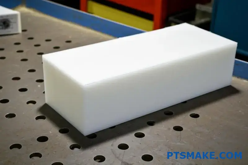
Material Selection Refinements
Not all UHMWPE grades machine identically:
- Virgin vs. Reprocessed: Virgin UHMWPE typically offers more predictable machining characteristics
- Compression Molded vs. Ram Extruded: Compression molded material often has more uniform internal stress distribution
- Additive-Enhanced Grades: Some grades with additives can offer improved dimensional stability
- Crosslinked Varieties: Consider partially crosslinked UHMWPE for reduced deformation tendency in certain applications
Post-Machining Techniques for Dimensional Stability
Even after machining is complete, several techniques can help ensure long-term dimensional stability.
Stress Relief Approaches
For components with demanding dimensional requirements:
- Thermal Cycling: Controlled heating below the material’s critical temperature followed by slow cooling
- Natural Aging: Allowing machined parts to stabilize at room temperature for 24-72 hours before final inspection
- Controlled Storage: Maintaining consistent temperature and humidity during the stabilization period
Inspection and Verification Strategies
To confirm dimensional stability:
- Sequential Measurements: Take measurements immediately after machining, then at 24, 48, and 72 hours
- Environmental Consistency: Ensure inspection conditions match the end-use environment
- Functional Gauging: Use application-specific fixtures to verify performance dimensions rather than just absolute measurements
By implementing these comprehensive strategies, we’ve been able to consistently produce complex UHMWPE components with exceptional dimensional stability at PTSMAKE. While this material presents unique machining challenges, its outstanding performance characteristics make mastering these techniques worthwhile for applications requiring superior wear resistance and impact strength.
What Surface Finish Can Be Achieved With UHMWPE Machining?
Have you ever received a UHMWPE part with an unacceptably rough surface that compromised your entire assembly? It’s a common frustration when working with this exceptional material – balancing its outstanding wear properties against the challenge of achieving the smooth, precise finish your application demands.
UHMWPE machining can achieve surface finishes from 125-250 μin Ra with standard techniques, while optimized processes using sharp tools, proper cooling, and appropriate cutting parameters can reach 32-63 μin Ra. Advanced techniques involving cryogenic cooling and diamond tooling can achieve even finer finishes of 16-25 μin Ra for specialized applications.
Understanding Surface Finish Factors in UHMWPE Machining
When machining UHMWPE (Ultra-High Molecular Weight Polyethylene), numerous factors influence the achievable surface finish. The material’s unique properties – including its extremely long molecular chains, viscoelastic behavior, and thermal characteristics – create specific challenges that must be addressed to achieve optimal results.
UHMWPE’s Material Properties and Their Impact on Surface Finish
UHMWPE’s molecular structure directly affects how it responds to machining operations:
- Molecular Weight: With molecular chains 10-100 times longer than standard polyethylene, UHMWPE’s entangled structure resists clean cutting and can create fibrous or stringy surface artifacts.
- Viscoelasticity: The material’s combined elastic and viscous behavior causes it to deform under cutting pressure and partially recover afterward, potentially leaving an irregular surface.
- Low Thermal Conductivity: UHMWPE dissipates heat poorly, leading to potential localized melting or smearing during machining that affects surface quality.
- Softening Temperature: With a relatively low softening point around 80°C (176°F), thermal effects can quickly compromise surface finish.
These inherent material characteristics create a baseline challenge for achieving fine surface finishes. However, with proper techniques and parameters, excellent results are still achievable.
Typical Surface Finish Ranges
Based on my experience at PTSMAKE, here are the typical surface finish ranges achievable with UHMWPE:
| Machining Method | Standard Practice | Optimized Process | Advanced Techniques |
|---|---|---|---|
| CNC Milling | 125-250 μin Ra | 32-63 μin Ra | 16-25 μin Ra |
| CNC Turning | 125-250 μin Ra | 32-63 μin Ra | 16-25 μin Ra |
| Drilling | 250-500 μin Ra | 125-250 μin Ra | 63-125 μin Ra |
| Reaming | 63-125 μin Ra | 32-63 μin Ra | 16-32 μin Ra |
These values represent achievable results under production conditions rather than laboratory ideals. The significantly better finishes in the "Advanced Techniques" column typically require specialized equipment, premium tooling, and optimized parameters that may not be economically viable for all applications.
Critical Cutting Tool Factors for Optimal Surface Finish
The selection and condition of cutting tools play a crucial role in determining surface finish quality when machining UHMWPE.
Tool Material and Coating Considerations
Different cutting tool materials offer varying performance levels:
- Carbide Tools: Provide good results when extremely sharp and properly designed for plastics machining.
- PCD (Polycrystalline Diamond): Offers superior edge retention and excellent surface finish capabilities, though at higher cost.
- Diamond-Coated Tools: Provide enhanced wear resistance while maintaining sharp cutting edges, beneficial for extended production runs.
- HSS (High-Speed Steel): Generally provides inferior results unless extremely sharp and used only for short durations.
At PTSMAKE, we primarily use premium carbide tools for most UHMWPE applications, reserving PCD tools for components requiring exceptional surface finishes or for high-volume production where the extended tool life justifies the investment.
Critical Tool Geometry Elements
Tool geometry significantly impacts surface finish quality:
- Rake Angle: High positive rake angles (15-20°) allow the tool to slice through the material rather than pushing it, creating cleaner surfaces.
- Relief Angle: Generous relief angles (10-15°) prevent the tool’s trailing edge from rubbing against the workpiece.
- Cutting Edge Sharpness: Extremely sharp edges are essential – even minor dulling can dramatically degrade surface finish.
- Edge Preparation: While sharp is critical, a properly honed edge (typically under 0.0005") provides better durability without sacrificing finish quality.
- Tool Nose Radius: For turning operations, larger nose radii generally produce better surface finishes up to a point, though excessively large radii can cause vibration issues.
Optimizing Machining Parameters for Superior Surface Finish
Carefully selected machining parameters are essential for achieving excellent surface finishes with UHMWPE.
Speed and Feed Relationships
The relationship between cutting speed and feed rate significantly impacts surface finish:
Cutting Speed (Surface Speed): For optimal finishes, moderate surface speeds are typically best – roughly 400-600 SFM (surface feet per minute) for most operations. Excessive speeds generate heat that can melt or smear the material, while insufficient speeds may not allow clean cutting.
Feed Rate: Lower feed rates generally produce better surface finishes but must be balanced against the risk of generating excessive heat through rubbing. For finishing operations, feed rates around 0.002-0.005 inches per revolution (turning) or inches per tooth (milling) typically yield excellent results.
Speed-Feed Balance: The optimal relationship between speed and feed is critical – a good starting point is maintaining chip loads that are slightly lower than those recommended for general-purpose machining of UHMWPE.
Depth of Cut Considerations
The depth of cut affects both heat generation and surface quality:
Roughing Operations: Heavier depths of cut (0.050-0.100") are acceptable for material removal but will not produce fine surface finishes.
Semi-Finishing: Moderate depths (0.010-0.030") with appropriate feeds and speeds begin to establish surface quality.
Finishing Passes: Light depths of cut (0.005-0.010") with optimized parameters produce the best surface finishes. In some cases, even lighter "spring passes" (0.001-0.003") can further improve results.
One effective strategy I’ve employed at PTSMAKE is the use of progressively lighter finishing passes, with each pass removing less material but improving surface quality.
Thermal Management for Enhanced Surface Quality
Controlling heat during machining is perhaps the most critical factor in achieving excellent surface finishes with UHMWPE.
Cooling Methods and Their Effect on Surface Finish
Different cooling approaches yield varying results:
| Cooling Method | Effect on Surface Finish | Best Applications |
|---|---|---|
| Flood Coolant | Good – prevents melting | General machining |
| Compressed Air | Fair – can leave dry, rough texture | Light cutting, where liquids must be avoided |
| Cryogenic Cooling | Excellent – prevents heat-related issues | Critical surface requirements |
| Mist Cooling | Good – balances cooling with minimal cleanup | Finishing operations |
The choice of coolant also matters. At PTSMAKE, we use water-soluble coolants specifically formulated for plastics machining, as these provide excellent heat removal without the risk of chemical interaction with the UHMWPE.
Preventing Heat-Related Surface Defects
Common heat-related surface problems include:
- Smearing: Material flows rather than cuts cleanly, creating a smeared appearance
- Galling: Material transfers to the cutting tool and then back to the workpiece, creating an irregular surface
- Melting: Localized melting creates a glossy, uneven surface
- Burnishing: Excessive friction burnishes rather than cuts the surface
To prevent these issues:
- Ensure adequate coolant flow directly at the cutting interface
- Implement periodic tool retractions during deep cuts to allow cooling
- Avoid dwelling or pausing with the tool in contact with the material
- Consider reducations in speeds and feeds when machining deep pockets where heat buildup is likely
Machine Dynamics and Surface Finish Quality
The stability and precision of the machining system directly influence achievable surface finish.
Vibration Minimization
Even minor vibration can significantly degrade surface finish quality in UHMWPE:
- Tool Overhang: Minimize tool extension from the holder to reduce deflection and vibration
- Machine Rigidity: Stiffer machine platforms produce better surface finishes
- Workpiece Support: Ensure adequate, even support to prevent workpiece movement or vibration
- Balanced Tooling: Use properly balanced tooling, particularly at higher spindle speeds
- Harmonic Avoidance: Select spindle speeds that avoid the natural frequency of the machine-tool-workpiece system
Toolpath Strategy and Surface Quality
How the tool engages with the material affects surface quality:
- Climb Milling vs. Conventional Milling: Climb milling (where the cutter rotation matches the direction of travel) typically produces better surface finishes in UHMWPE
- Constant Engagement: Toolpaths that maintain consistent tool engagement help prevent surface variations
- Direction Changes: Minimize sudden direction changes, which can leave marks on the surface
- Feed Rate Transitions: Implement smooth acceleration/deceleration to prevent surface artifacts at transitions
Post-Machining Surface Enhancement Techniques
When machining alone doesn’t achieve the required surface finish, several post-processing methods can enhance UHMWPE surfaces.
Mechanical Finishing Methods
Several mechanical approaches can improve as-machined surfaces:
- Light Sanding: Using progressively finer abrasives (starting at 320-400 grit) can improve surface finish but should be done carefully to avoid generating heat
- Media Tumbling: Non-abrasive media in vibratory systems can gently smooth surfaces without dimensional impact
- Polishing: Specialized plastic polishing compounds with soft wheels can achieve extremely smooth finishes (under 8 μin Ra) for critical applications
Thermal Smoothing Approaches
For some applications, controlled thermal treatments can enhance surface quality:
- Flame Treatment: Brief exposure to a regulated flame can slightly melt and smooth the surface (requires careful control)
- Hot Air Smoothing: Controlled application of heated air can achieve similar results with less risk
- Vapor Smoothing: Not commonly used for UHMWPE but can be employed in specialized cases
These thermal approaches must be carefully controlled to prevent dimensional changes or material property degradation.
Industry-Specific Surface Finish Requirements
Different applications have varying surface finish requirements for UHMWPE components.
Medical Industry Standards
For medical applications, surface finish requirements are particularly stringent:
- Implantable Components: Often require finishes of 16 μin Ra or better to prevent wear particle generation
- Instrument Components: Typically need 32-63 μin Ra to ensure smooth operation and prevent contamination traps
- Regulatory Compliance: May specify particular surface parameters beyond Ra, including Rz (average maximum height) and Rq (root mean square roughness)
Industrial Applications
Industrial UHMWPE components have application-specific requirements:
- Bearing Surfaces: Usually require 32-63 μin Ra to optimize tribological performance6 and minimize wear
- Sealing Surfaces: Often need 32-63 μin Ra to ensure proper sealing without excessive friction
- Material Handling Components: Can often function well with standard machined finishes (125-250 μin Ra)
- Wear Plates: Typically acceptable with standard finishes unless friction coefficients must be tightly controlled
Case Study: Achieving Premium Finishes in UHMWPE Components
At PTSMAKE, we recently faced a challenging project involving UHMWPE components for a medical device application requiring exceptional surface finish throughout complex geometries. The client specification called for surfaces of 16-25 μin Ra on all critical surfaces, including internal features.
To achieve this demanding requirement, we implemented a comprehensive approach:
- Material Selection: Used premium-grade medical UHMWPE with consistent molecular weight distribution
- Tool Selection: Employed custom PCD tooling with specialized geometries for plastic machining
- Parameter Optimization: Developed specific speeds and feeds through iterative testing
- Thermal Management: Implemented high-pressure coolant delivery with specialized nozzles
- Multiple Finishing Passes: Utilized progressive light finishing passes with decreasing depth of cut
- In-Process Verification: Performed regular surface finish measurements to ensure consistency
Through this systematic approach, we achieved consistent surface finishes of 12-18 μin Ra, exceeding the client’s requirements while maintaining tight dimensional tolerances.
Practical Recommendations for Optimizing Surface Finish
Based on my years of experience machining UHMWPE at PTSMAKE, here are my top recommendations for achieving excellent surface finishes:
- Prioritize Sharp Tooling: Nothing impacts surface finish more than tool sharpness – replace or resharpen tools at the first sign of wear
- Control Heat Generation: Implement effective cooling strategies, as thermal issues are the primary cause of poor surface finishes
- Balance Parameters: Find the optimal balance between speed and feed – neither too aggressive nor too conservative
- Consider Machine Capabilities: Match your approach to your machine’s rigidity and capabilities
- Test and Refine: Develop parameters through systematic testing rather than relying solely on theoretical values
- Implement Appropriate Post-Processing: When necessary, use suitable post-machining techniques to achieve final finish requirements
While UHMWPE presents unique machining challenges, proper techniques can achieve surface finishes that meet or exceed the requirements of even the most demanding applications, from industrial wear components to precision medical devices.
Learn about this critical property for extending component lifespan. ↩
Discover how this remarkable low-temperature performance can benefit your cold-environment applications. ↩
Learn about specialized techniques to overcome elasticity challenges in thread machining. ↩
Discover how this property affects material performance in high-wear applications. ↩
Discover specialized techniques that can drastically improve your UHMWPE machining results. ↩
Learn how surface finish affects wear rates and component lifespan in sliding and bearing applications. ↩