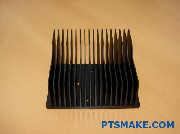
What Makes Aluminum The Preferred Heat Sink Material
Ever wondered why almost every electronic device in your home stays cool under pressure? The secret lies in a humble metal that works silently behind the scenes to prevent your devices from overheating.
Aluminum stands as the cornerstone material in thermal management solutions across industries due to its unique combination of high thermal conductivity, lightweight nature, affordability, and resistance to environmental factors that would compromise other materials.
In my years working with thermal management solutions at PTSMAKE, I’ve seen firsthand how material selection can make or break a product’s performance and lifespan. Aluminum heat sinks have consistently proven themselves as the industry standard, and for good reasons that extend beyond just their cooling capabilities.
The Science Behind Aluminum’s Cooling Power
Aluminum’s thermal conductivity of approximately 167 W/m-K places it among the most efficient commercially viable heat-dissipating materials. This property allows it to rapidly draw heat away from critical components and distribute it across the sink’s surface area. What makes this particularly impressive is that aluminum achieves this while maintaining a density of just 2.7 g/cm³ – nearly one-third that of copper, its closest competitor.
When heat needs to move quickly from a source (like a CPU or power transistor) to the surrounding air, the thermal gradient1 created drives this transfer. Aluminum excels at maintaining this gradient without creating excessive weight burdens on the overall system design.
Physical Properties Comparison
| Material | Thermal Conductivity (W/m-K) | Density (g/cm³) | Relative Cost | Machinability |
|---|---|---|---|---|
| Aluminum | 167-229 | 2.7 | Low | Excellent |
| Copper | 385-400 | 8.96 | High | Good |
| Steel | 43-54 | 7.85 | Medium | Moderate |
| Ceramic | 20-30 | 3.9 | Very High | Poor |
Cost-Effectiveness Without Compromise
The economic advantage of aluminum cannot be overstated. When manufacturing thousands of heat sinks at PTSMAKE, we consistently find that aluminum offers the best performance-to-cost ratio by a significant margin. The material is abundant in the earth’s crust, making up approximately 8% of its mass, which keeps raw material costs relatively stable.
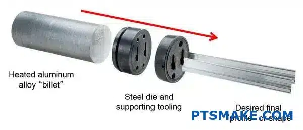
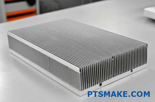
Manufacturing processes for aluminum are also well-established and efficient. The metal’s natural malleability makes it ideal for extrusion – one of the most cost-effective production methods for heat sinks. This allows for complex fin geometries that maximize surface area without expensive machining operations.
Production Efficiency Factors
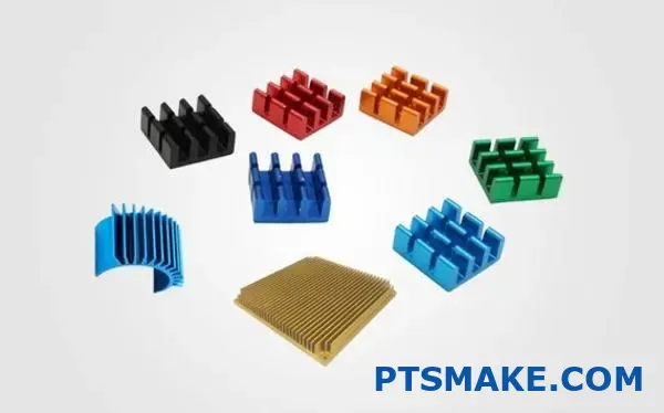
- Formability: Aluminum’s excellent formability allows for varied heat sink designs from simple flat plates to complex finned structures
- Machining Speed: CNC machines can process aluminum 3-5 times faster than harder metals
- Tool Wear: Cutting tools last longer when working with aluminum compared to harder materials
- Secondary Operations: Aluminum requires minimal finishing work after primary manufacturing
Environmental Resilience
One often overlooked advantage of aluminum is its exceptional resistance to environmental factors. The natural formation of aluminum oxide on its surface creates a protective layer that prevents further corrosion – a self-healing characteristic that gives aluminum heat sinks tremendous longevity.
In industries where devices must operate in humid or chemically aggressive environments, this property proves invaluable. I’ve seen aluminum heat sinks from outdoor telecommunications equipment that remained fully functional after a decade of exposure to the elements.
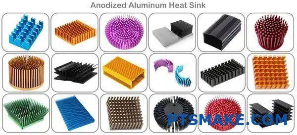
For enhanced protection, aluminum heat sinks can be anodized – an electrochemical process that thickens and strengthens the natural oxide layer. This treatment can also be used to add color for aesthetic purposes without compromising thermal performance.
Versatility in Application
The versatility of aluminum extends to virtually every industry requiring thermal management:
Industry Applications
- Consumer Electronics: From laptops to gaming consoles, aluminum keeps processors running at optimal temperatures
- Automotive: Engine control units, LED headlights, and power inverters for electric vehicles all rely on aluminum cooling
- Industrial: Power supplies, motor drives, and automation equipment depend on aluminum heat sinks
- Telecommunications: Cell towers and network infrastructure equipment use aluminum for passive cooling in remote locations
- Medical Devices: Diagnostic equipment and imaging systems use aluminum to maintain precise operating temperatures
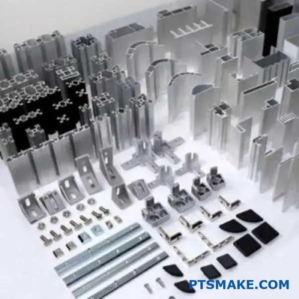
Customization Capabilities
At PTSMAKE, we regularly customize aluminum heat sinks to meet specific thermal challenges. The material lends itself to nearly any manufacturing process – from simple extrusion to complex CNC machining, die casting, or stamping. This flexibility allows engineers to optimize designs for their specific thermal requirements rather than compromising with off-the-shelf solutions.
The ability to create custom fin geometries, mounting features, and surface treatments makes aluminum the most adaptable heat sink material. Whether the application needs maximum airflow in a server farm or silent passive cooling in consumer electronics, aluminum can be engineered to deliver optimal performance.
Common Heat Sink Profiles And Their Applications
Ever seen those metallic fins inside your computer or behind LED lights? Those aren’t just for show – they’re engineering marvels that prevent your favorite devices from burning up during operation.
The heat sink profile you choose can make or break your thermal management system. Each design – from simple extruded shapes to complex pin arrays – serves a specific purpose optimized for airflow patterns, space constraints, and thermal requirements across various applications.
With over 15 years in precision manufacturing, I’ve witnessed firsthand how the right heat sink profile can significantly impact device performance and longevity. At PTSMAKE, we’ve designed and manufactured thousands of custom heat sink solutions, and I’ve come to appreciate the nuanced differences between various profiles and their ideal applications.
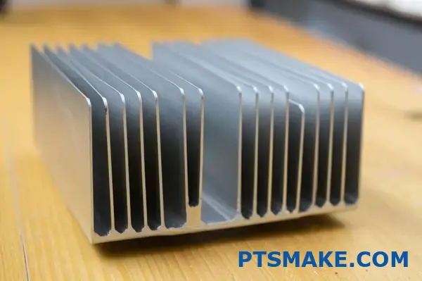
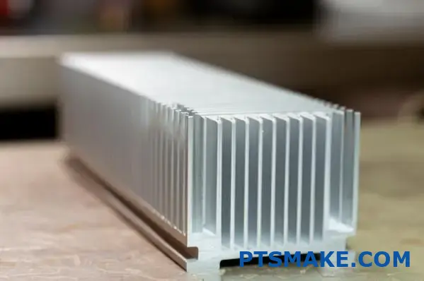
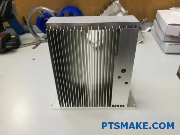
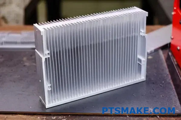
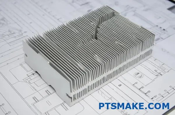
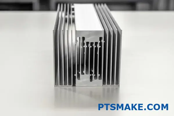
Extruded Heat Sink Profiles
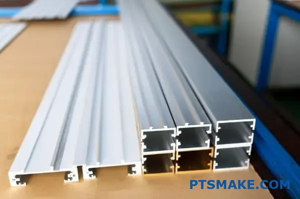
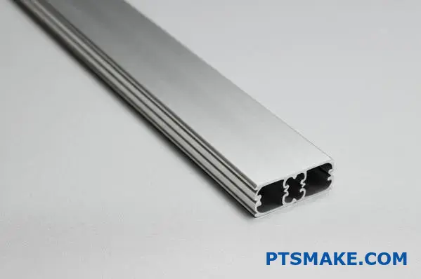
Extruded aluminum profiles represent the most common and cost-effective heat sink design in the market today. The manufacturing process involves pushing aluminum through a die to create continuous profiles with consistent cross-sections.
Advantages of Extruded Profiles
- Cost-Efficiency: The extrusion process allows for high-volume production with minimal waste
- Design Flexibility: Can create various fin heights, thicknesses, and spacings from a single die
- Consistent Quality: Uniform cross-sections ensure predictable thermal performance
Ideal Applications
Extruded profiles excel in applications where airflow is relatively predictable and unidirectional. They’re commonly used in:
- Power supplies and amplifiers
- LED lighting systems
- Telecommunications equipment
- Motor controllers
The limitation of extruded profiles comes from their single-direction fin orientation. When airflow changes direction or becomes turbulent, their cooling efficiency can drop significantly.
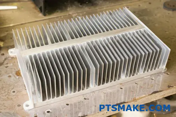
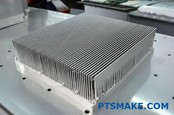
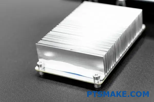
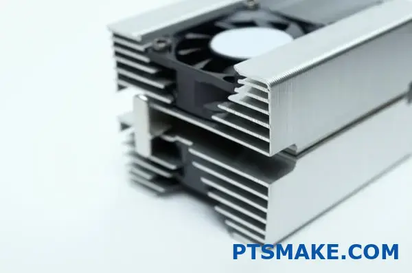
Plate Fin Heat Sink Profiles
Plate fin heat sinks feature multiple thin metal sheets (fins) attached to a base plate. This design allows for greater surface area in compact spaces.
Manufacturing Methods
- Skived Fin: Created by skiving (peeling up) material from the base plate
- Bonded Fin: Individual fins bonded to the base through soldering, brazing, or adhesives
- Folded Fin: Continuous sheet metal folded into accordion-like structures
Performance Characteristics
| Profile Type | Thermal Resistance | Surface Area Density | Weight | Cost |
|---|---|---|---|---|
| Skived Fin | Low | Very High | Medium | Medium-High |
| Bonded Fin | Very Low | High | Medium | High |
| Folded Fin | Low-Medium | High | Low | Medium |
Plate fin heat sinks are ideal for applications requiring high cooling capacity in limited spaces, such as:
- High-performance computing
- Military and aerospace electronics
- Medical imaging equipment
- Power conversion systems
At PTSMAKE, we’ve implemented plate fin designs for clients in the medical device industry where compact, efficient cooling is critical for diagnostic equipment reliability.
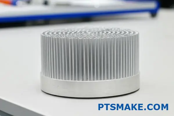
Round Pin Heat Sink Profiles
Round pin heat sinks utilize arrays of cylindrical pins extending from a base plate. This design offers unique advantages for omnidirectional airflow environments.
Key Benefits
- Omnidirectional Cooling: Performs well regardless of airflow direction
- Pressure Drop Reduction: Allows air to flow around pins with less resistance
- Turbulence Generation: Creates beneficial air mixing for enhanced heat transfer
- Dust Resistance: Less prone to dust accumulation compared to tight fin spacing
The manufacturing process typically involves CNC machining for precision applications or casting for higher volume production. At PTSMAKE, our CNC capabilities allow us to create custom pin patterns optimized for specific thermal requirements.
Round pin heat sinks find their place in applications where:
- Airflow direction may change or is unpredictable
- Natural convection is the primary cooling method
- Fan redundancy or failure is a concern
- Dust-rich environments present maintenance challenges
Elliptical Pin Profiles
An evolution of round pin designs, elliptical pin heat sinks represent a middle ground between traditional pins and straight fins.
Comparative Advantages
- Aerodynamic Efficiency: Reduced drag compared to round pins
- Surface Area: Greater surface-to-volume ratio than round pins
- Directional Performance: Better in semi-directional airflow situations
I’ve observed that elliptical designs offer approximately 10-15% better thermal performance than round pins in directed airflow while maintaining about 70% of the omnidirectional capability. This makes them ideal for applications where:
- Airflow has a predominant direction but may fluctuate
- Space constraints limit traditional straight fin designs
- Pressure drop must be minimized while maximizing cooling
Specialized Heat Sink Profiles
Beyond the standard profiles, several specialized designs address unique thermal challenges:
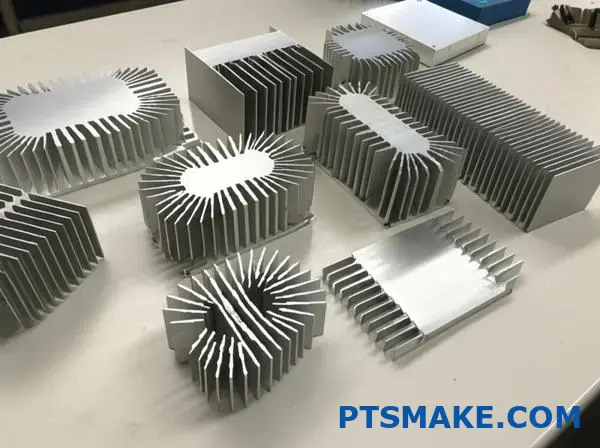
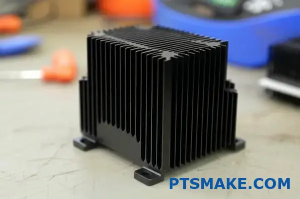
Radial Fin Heat Sinks
These feature fins extending radially from a central point, creating a star-like pattern. They excel in:
- LED spotlights and downlights
- CPU coolers with top-down fans
- Centralized heat source applications
Forged Heat Sinks
Created through metal forging processes, these heat sinks offer exceptional thermal performance through:
- Optimized grain structure for improved conductivity
- Higher fin density in critical areas
- Enhanced mechanical strength for high-stress environments
Through my work at PTSMAKE with aerospace and military clients, I’ve seen forged heat sinks provide up to 20% better thermal conductivity2 in high-reliability applications where failure isn’t an option.
Zipper Fin Designs
A specialized variation of plate fins, zipper fins interlock in alternating patterns to create turbulent airflow. These are particularly effective in:
- High-power density computing
- Telecommunications base stations
- Industrial power conversion equipment
Selecting the right heat sink profile requires balancing thermal requirements, space constraints, airflow characteristics, and budget considerations. At PTSMAKE, we guide our clients through this decision process by analyzing their specific application needs rather than defaulting to a one-size-fits-all approach.
Selecting The Right Size For Maximum Thermal Efficiency
Have you ever watched your laptop shut down from overheating during an important presentation? That frustrating moment illustrates why properly sized cooling systems aren’t just technical details—they’re the difference between reliable operation and costly failures.
Choosing the right heat sink dimensions is a critical engineering decision that balances thermal requirements with practical constraints. The perfect aluminum heat sink isn’t just about material quality; it’s about precisely matching size, fin density, and overall geometry to your specific thermal load and operating environment.
When it comes to thermal management, size truly matters. Through my work at PTSMAKE, I’ve seen countless projects succeed or fail based on heat sink sizing decisions. Let me share what I’ve learned about selecting the optimal dimensions for your aluminum heat sink to achieve maximum thermal efficiency.
Understanding Your Thermal Requirements
Before selecting any heat sink dimensions, you must thoroughly understand your system’s thermal profile. This foundational step ensures your cooling solution matches your actual needs rather than generic specifications.
Heat Dissipation Calculation
The first step is calculating the total heat load your components generate. This requires knowing:
- Power consumption of each heat-generating component
- Efficiency ratings to determine how much power converts to heat
- Duty cycle patterns during typical operation
For most electronic components, the heat generated (in watts) can be estimated using this formula:
Heat Generated = Power Input × (1 – Efficiency)
For example, a 100W power amplifier operating at 75% efficiency will generate approximately 25W of heat that needs dissipation. This becomes your baseline requirement.
Thermal Resistance Targets
Once you know your heat load, the next consideration is the maximum allowable temperature rise. Every component has a maximum operating temperature, and staying well below this threshold improves reliability and longevity.
The thermal resistance required (in °C/W) can be calculated as:
Required Thermal Resistance = (Tmax – Tambient) ÷ Heat Load
Where:
- Tmax is the maximum allowable component temperature
- Tambient is the ambient air temperature
This calculation provides the maximum thermal resistance your heat sink can have while maintaining safe operating temperatures.
Dimensional Factors Affecting Performance
Multiple dimensional factors influence heat sink performance, each creating tradeoffs between thermal efficiency, weight, cost, and space requirements.
Base Plate Dimensions
The base plate serves as the primary heat collector and distributor. Its dimensions are critical for several reasons:
| Dimension | Influence on Performance | Optimization Consideration |
|---|---|---|
| Thickness | Heat spreading capability | Thicker bases improve heat spreading but add weight and cost |
| Surface Area | Contact with heat source | Should match or exceed the footprint of heat-generating components |
| Flatness | Thermal interface quality | Precision machining reduces thermal resistance at contact points |
At PTSMAKE, we typically recommend base plate thicknesses between 3-10mm depending on application requirements. For high-power applications, thicker bases provide better heat spreading, while space-constrained designs may require thinner profiles with higher conductivity alloys.
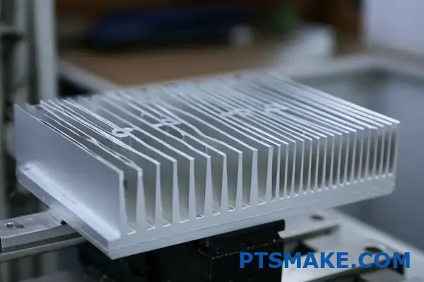
Fin Dimensions and Spacing
Fins dramatically increase surface area for heat transfer to the surrounding air. Their dimensions significantly impact cooling efficiency:
Fin Height
Taller fins provide more surface area but face diminishing returns as height increases. After a certain point (typically when fin height exceeds 10× the spacing between fins), airflow becomes restricted, and efficiency drops.
Fin Thickness
Thinner fins allow for more fins in the same space, increasing surface area. However, excessively thin fins:
- Conduct heat less effectively from the base
- May warp during manufacturing
- Can be damaged during handling
Fin Spacing
The gap between fins is perhaps the most critical dimensional factor affecting real-world performance. Too close, and airflow is restricted; too far apart, and surface area is sacrificed.
For natural convection, optimal fin spacing typically ranges from 8-12mm, while forced convection applications can use much tighter spacing (2-5mm) due to the pressure differential created by fans.
Overall Footprint Considerations
Beyond thermal performance, practical considerations often dictate heat sink dimensions:
- Available mounting space within the enclosure
- Weight limitations for portable or suspended applications
- Clearance for other components and assembly requirements
- Airflow patterns within the system
Application-Specific Sizing Guidelines
Different applications have unique requirements that influence optimal heat sink dimensions.
High-Airflow Environments
In systems with powerful fans or blowers, heat sinks can be designed with:
- Higher fin density (1-2mm spacing)
- Taller fins (up to 50mm in some cases)
- Smaller overall footprint
- Thinner base plates (3-5mm)
These environments permit higher-density designs because the forced air overcomes the resistance created by tightly packed fins.
Natural Convection Applications
For passively cooled systems, heat sink dimensions must be more generous:
- Wider fin spacing (8-12mm)
- Lower profile fins (typically 25mm or less)
- Larger footprint to compensate for lower cooling efficiency
- Thicker base plates (6-10mm) for better heat spreading
Space-Constrained Designs
In the tightest spaces, such as slim laptops or compact medical devices, dimensional optimization becomes critical:
- Custom fin patterns that match available airflow paths
- Vapor chambers integrated into the base plate to improve heat spreading
- Hybrid materials like aluminum-graphite composites for directional heat transfer
- Staggered fin heights to maximize surface area in irregular spaces
At PTSMAKE, we’ve developed specialized anisotropic heat spreaders3 for ultra-thin devices that outperform traditional aluminum solutions by channeling heat in preferred directions.
Balancing Size with Manufacturing Considerations
The perfect thermal design on paper must also be practical to manufacture consistently. Heat sink dimensions should align with available manufacturing methods:
- Extrusion Limits: Standard aluminum extrusions have aspect ratio limitations (typically 10:1 for fin height:thickness)
- CNC Machining Constraints: Deep, narrow fin channels require specialized tooling
- Die Casting Parameters: Wall thickness variations and draft angles must be considered
- Forging Capabilities: Material flow affects achievable geometries
When designing custom heat sinks, working closely with your manufacturer early in the process ensures your thermal requirements align with production capabilities. At PTSMAKE, we provide design-for-manufacturing feedback that often improves both thermal performance and production efficiency.
Scaling Heat Sink Size to Thermal Load
One approach I’ve found effective is scaling heat sink volume proportionally to thermal load while maintaining optimal fin geometry. As a rule of thumb:
- For every doubling of thermal load, increase heat sink volume by approximately 75-100%
- Maintain the same fin spacing for similar airflow conditions
- Increase base plate thickness proportionally to heat load for better spreading
- Consider splitting very large thermal loads across multiple smaller heat sinks
This approach provides predictable scaling of thermal performance while maintaining manufacturing feasibility.
Mounting Options For Secure Thermal Connection
Ever struggled with a device that overheats despite having a premium heat sink? The culprit might not be the heat sink itself, but how it’s attached. A perfect heat sink poorly mounted is like a high-performance tire with loose lug nuts—disaster waiting to happen.
Securing your aluminum heat sink properly is the unsung hero of thermal management. The mounting method you choose directly impacts thermal transfer efficiency, long-term reliability, and maintenance access, making it as crucial as the heat sink material itself.
In thermal management, the connection between heat-generating components and their cooling solutions forms the critical pathway for heat dissipation. Having worked with countless thermal management challenges at PTSMAKE, I’ve found that even the most advanced aluminum heat sink can fail if improperly mounted. Let me share insights on the most effective mounting options and when to use each.
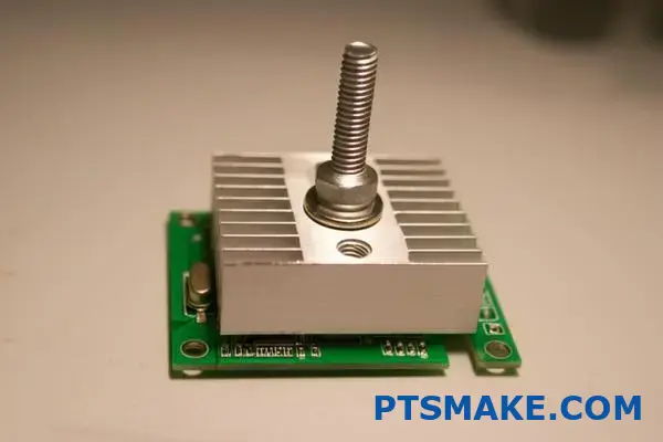
Push Pin Mounting Systems
Push pins represent one of the simplest and most cost-effective mounting solutions for aluminum heat sinks, particularly in high-volume consumer electronics.
How Push Pins Work
Push pins are plastic or metal fasteners designed to snap through pre-drilled holes in both the heat sink and PCB. They feature:
- A flexible body that compresses during insertion
- Barbs or expanding heads that provide retention force
- Pre-loaded spring tension in some advanced designs
The installation process is straightforward:
- Align the heat sink with mounting holes
- Insert pins through the heat sink and PCB
- Apply downward pressure until pins lock into place
Advantages and Limitations
| Advantage | Limitation |
|---|---|
| Tool-free installation | Limited compression force |
| Low cost | Potential for stress relaxation over time |
| Quick assembly/disassembly | Less suitable for high-vibration environments |
| No risk of PCB damage from overtightening | May require access to both sides of PCB |
Best Applications
Push pin mounting works exceptionally well for:
- Consumer electronics like laptops and desktop computers
- Low to medium-power applications (typically under 30W)
- Situations requiring frequent maintenance or part replacement
- Products with strict cost constraints
At PTSMAKE, we’ve optimized push pin designs for clients seeking balance between secure mounting and easy serviceability, particularly in computer hardware and consumer electronics.
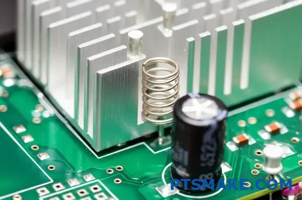
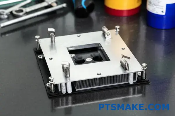
Spring Clip Systems
Spring clips provide excellent pressure distribution while accommodating thermal expansion and contraction cycles.
Types of Spring Clip Mounts
- Z-Clips: Z-shaped metal clips that hook onto a component’s edges
- Tension Clips: Arched metal springs that apply pressure across the heat sink
- Retention Frames: Complete frames that distribute pressure evenly
Spring clips work by applying continuous downward force, maintaining consistent thermal interface contact even through temperature cycles and vibration.
Design Considerations
When implementing spring clip mounting, several factors influence performance:
- Material Selection: Stainless steel offers excellent resilience and corrosion resistance
- Spring Rate: Must provide adequate pressure without risking component damage
- Contact Points: Pressure should be centered over the heat source
- Clearance Requirements: Surrounding components must accommodate clip geometry
Optimal Use Cases
Spring clips excel in:
- High-vibration environments like automotive applications
- Systems undergoing frequent thermal cycling
- Applications where consistent pressure is critical
- Designs where minimal z-height is available for mounting hardware
One notable advantage is the creep resistance4 these systems provide, maintaining consistent pressure over years of temperature fluctuations where other fastening methods might loosen.
Screw Mounting Systems
For high-power applications and situations requiring maximum thermal transfer efficiency, screw mounting remains the gold standard.
Screw Mount Configurations
- Direct Threading: Heat sinks with threaded holes accept screws directly
- Through-Hole Mounting: Screws pass through the heat sink into standoffs or nuts
- Backing Plate Systems: Distribute force across the PCB back side
Critical Installation Practices
The effectiveness of screw mounting depends heavily on proper installation techniques:
- Torque Specification: Apply consistent, specified torque to all fasteners
- Tightening Sequence: Use cross-pattern or star-pattern tightening sequence
- Thread-locking Compounds: Consider medium-strength compounds for vibration resistance
- Thermal Interface Material: Apply proper amount and coverage before mounting
Performance Benefits
Screw mounting provides several key advantages:
- Highest possible mounting pressure (typically 30-70 PSI)
- Precise pressure control through torque specifications
- Excellent long-term stability
- Superior thermal interface compression
In our manufacturing facility at PTSMAKE, we’ve developed specialized torque sequences for different heat sink geometries to prevent warping while ensuring optimal pressure distribution.
Adhesive Mounting Solutions
Thermal adhesives offer unique benefits in specific applications, particularly where mechanical fasteners are impractical.
Types of Thermal Adhesives
- Epoxy-Based Adhesives: Highest bond strength but permanent installation
- Silicone Thermal Adhesives: More flexible, accommodates thermal expansion
- Phase-Change Adhesives: Soften at operating temperatures for improved contact
- Thermally Conductive Tapes: Double-sided adhesive with embedded thermal particles
Application Methodology
Proper adhesive application significantly impacts performance:
- Clean both surfaces thoroughly with isopropyl alcohol
- Apply adhesive in uniform thickness (typically 0.1-0.3mm)
- Use fixturing during curing to maintain position and pressure
- Allow full cure time before subjecting to stress or heat
Situations Favoring Adhesive Mounting
Thermal adhesives are particularly valuable when:
- No mounting holes are available
- Extremely low profile is required
- Components have irregular surfaces
- Vibration isolation is beneficial
- Installation must be performed in awkward orientations
We’ve successfully employed specialized thermal adhesives for clients in the LED lighting industry, where heat sinks must be bonded to challenging surfaces like glass and ceramic substrates.
Hybrid Mounting Approaches
In many real-world applications, combining mounting methods yields superior results.
Common Hybrid Configurations
- Adhesive + Mechanical Retention: Primary bond with mechanical backup
- Central Screw + Peripheral Clips: Concentrated pressure at heat source with distributed retention
- Push Pins + Thermal Adhesive: Mechanical alignment with additional thermal coupling
These approaches provide redundancy while optimizing thermal transfer at critical junctions.
Selecting the Optimal Mounting Method
When advising clients at PTSMAKE, I consider several factors to recommend the best mounting approach:
- Thermal Load: Higher power requires more secure mounting
- Environmental Conditions: Vibration, shock, orientation, and temperature extremes
- Service Requirements: Need for maintenance access or replacement
- Manufacturing Constraints: Assembly process compatibility
- Cost Sensitivity: Budget implications for high-volume production
The decision matrix often looks like this:
| Factor | Push Pins | Spring Clips | Screws | Adhesives |
|---|---|---|---|---|
| Thermal Efficiency | Good | Very Good | Excellent | Good-Excellent |
| Installation Effort | Minimal | Low | Moderate | Moderate |
| Reworkability | Excellent | Very Good | Good | Poor |
| Vibration Resistance | Fair | Very Good | Excellent | Good |
| Cost | Low | Low-Moderate | Moderate | Moderate-High |
Thermal Interface Materials and Their Impact
The mounting method must work in concert with appropriate thermal interface materials (TIMs) to maximize heat transfer:
- Push Pins: Work well with thermal pads that compensate for lower mounting pressure
- Spring Clips: Compatible with phase-change materials that respond to applied pressure
- Screws: Can fully compress thin thermal greases for optimal performance
- Adhesives: Often incorporate their own thermal transfer properties
Proper selection and application of TIMs can compensate for limitations in mounting pressure or surface irregularities.
In my experience at PTSMAKE, the mounting method choice often makes a 15-30% difference in overall thermal performance—a margin that can determine whether a design succeeds or fails in the field.
Custom Solutions vs. Standard Profiles: Making The Right Choice
Have you ever been torn between the convenience of grabbing an off-the-shelf heat sink and the performance promise of a custom solution? This common engineering dilemma affects not just your device’s cooling but potentially its entire market success.
Choosing between standard aluminum heat sink profiles and custom solutions involves balancing immediate costs against long-term performance benefits. While standard options offer faster deployment and lower initial investment, custom designs can deliver optimized cooling specifically tailored to your unique thermal challenges.
When it comes to thermal management decisions, the standard versus custom debate represents one of the most consequential choices you’ll make. Having guided numerous clients through this decision process at PTSMAKE, I’ve developed a framework to help engineers make the right choice for their specific applications.
Standard Profiles: The Case for Off-the-Shelf Solutions
Standard aluminum heat sink profiles offer compelling advantages that make them the right choice for many applications. These pre-designed, readily available options have earned their place in the thermal management toolkit.
Cost Advantages of Standard Profiles
The financial benefits of standard profiles extend beyond just the unit price:
- Lower Tooling Investment: No custom die or tooling costs
- Reduced Engineering Time: Minimal design validation required
- Quick Procurement: Available from distribution channels with short lead times
- Economy of Scale: High-volume production reduces per-unit costs
For startups and companies with budget constraints, these cost savings can be substantial. One project I managed at PTSMAKE saved approximately 40% on initial development costs by adapting a standard profile rather than creating a custom solution.
When Standard Profiles Excel
Standard profiles perform exceptionally well when:
- Thermal loads are moderate: Most standard profiles can handle up to 50-100W depending on size
- Space constraints are flexible: When you can accommodate standard dimensions
- Time-to-market is critical: Launching quickly often outweighs perfect optimization
- Production volumes are low to medium: Custom tooling costs can’t be amortized effectively
- Application is non-specialized: Common cooling needs in standard environments
Industry Applications for Standard Profiles
| Industry | Typical Applications | Benefits of Standard Profiles |
|---|---|---|
| Consumer Electronics | Home routers, audio equipment | Cost-effective, adequate cooling |
| Industrial Control | PLCs, HMI interfaces | Quick replacement, standardization |
| Lighting | LED drivers, low-power fixtures | Readily available, proven designs |
| Telecommunications | Network switches, signal boosters | Reliability through established designs |
Custom Solutions: Optimized for Your Specific Needs
While standard profiles offer convenience, custom-designed aluminum heat sinks provide performance advantages that can prove decisive in challenging applications.
Performance Advantages of Custom Solutions
Custom heat sink designs allow for:
- Optimized Thermal Performance: Precisely matched to your specific heat load
- Space Optimization: Designed to fit your exact mechanical constraints
- Airflow Integration: Tailored to your system’s airflow patterns
- Weight Reduction: Material used only where needed
- Integration of Additional Features: Mounting points, component housing, or structural support
When Custom Solutions Make Financial Sense
Despite higher initial costs, custom heat sinks often deliver superior return on investment when:
- Production volumes are high: Tooling costs are distributed across many units
- Performance requirements are stringent: The thermal margin is critical
- Space is severely constrained: Every millimeter matters
- System reliability is paramount: Failure costs are prohibitively high
- Integration can eliminate other components: Reducing overall system cost
For example, a medical imaging client at PTSMAKE initially balked at the custom tooling costs for a specialized heat sink. However, the optimized design allowed for passive cooling where the standard solution would have required fans, ultimately reducing system complexity, power consumption, and noise while improving reliability.
Production Volume Considerations
The production volume inflection point—where custom solutions become more economical than standard profiles—varies based on several factors:
Low Volume Production (Under 1,000 units)
For prototype runs and limited production, standard profiles almost always make financial sense. The exceptions include:
- Ultra-high-value products where performance justifies engineering costs
- Applications where thermal performance is mission-critical
- Situations where space constraints absolutely cannot accommodate standard profiles
Medium Volume Production (1,000-10,000 units)
This range represents the decision "sweet spot" where careful analysis is essential:
- Custom extrusion dies5 typically become cost-effective around 3,000-5,000 units
- Modified standard profiles (customized finishing on standard extrusions) offer a middle-ground approach
- CNC-machined custom solutions remain expensive but may be justified by performance needs
High Volume Production (10,000+ units)
At high volumes, custom solutions typically deliver better overall value:
- Tooling costs become negligible on a per-unit basis
- Material optimization reduces ongoing production costs
- Performance advantages translate to marketable product benefits
Cost Constraint Analysis
When evaluating cost constraints, consider these often-overlooked factors:
Beyond Initial Price
- Operational Costs: Higher-performing thermal solutions may reduce energy consumption
- Warranty Claims: Improved cooling reduces component failures and returns
- Assembly Time: Custom designs can incorporate features that speed production
- Inventory Management: Standard profiles may require less inventory investment
- Manufacturing Flexibility: Standard profiles allow easier changes to production volumes
Hidden Costs of Standard Profiles
The "bargain" of standard profiles sometimes comes with unexpected expenses:
- Adapters or modifications needed to fit standard profiles
- Additional assembly steps to mount non-optimized solutions
- Potential for overdesign (using larger heat sinks than necessary)
- Performance compromises that affect other system components
Specific Cooling Requirement Factors
Your application’s specific cooling requirements should heavily influence your standard vs. custom decision:
Thermal Performance Requirements
- Maximum Component Temperature: How close to thermal limits can you operate?
- Temperature Uniformity: Do hot spots need to be specifically addressed?
- Transient Performance: How quickly must heat be dissipated during load spikes?
- Ambient Conditions: What are the extremes of the operating environment?
Physical Design Constraints
- Weight Limitations: Is the application weight-sensitive (portable, aerospace)?
- Dimensional Constraints: Are there strict space limitations?
- Orientation Factors: Will the heat sink operate in variable orientations?
- Mounting Interface: What surface area is available for thermal contact?
Decision Framework
At PTSMAKE, we use a structured approach to help clients make the standard vs. custom decision:
- Performance Gap Analysis: Determine if standard profiles meet minimum thermal requirements
- Total Cost of Ownership Calculation: Include all lifecycle costs
- Time-to-Market Assessment: Evaluate schedule impacts
- Volume/Cost Projection: Calculate the crossover point where custom becomes more economical
- Risk Evaluation: Assess consequences of thermal management failure
This systematic approach ensures decisions balance immediate needs with long-term considerations.
Hybrid Approaches
In many cases, the best solution falls between purely standard and fully custom designs:
- Modified Standard Profiles: Standard extrusions with custom machining or features
- Modular Systems: Standard components configured in custom arrangements
- Custom Base with Standard Fins: Optimized contact with standard cooling elements
- Semi-Custom Assemblies: Combining standard profiles in novel configurations
These approaches offer a compelling middle ground, providing many custom benefits while reducing engineering costs and lead times.
Surface Treatments And Their Impact On Performance
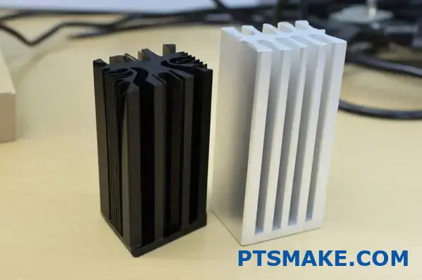
Ever wondered why some aluminum heat sinks look shiny while others appear dull black? These aren’t just aesthetic choices—they’re strategic engineering decisions that can dramatically impact how effectively your device stays cool under pressure.
Surface treatments for aluminum heat sinks go far beyond mere appearance, directly influencing thermal conductivity, corrosion resistance, and long-term reliability. The right finish can enhance performance by up to 25% while extending service life in harsh environments from years to decades.
When it comes to optimizing aluminum heat sinks, surface treatments represent one of the most powerful yet often overlooked variables in the thermal management equation. With my experience managing countless thermal solutions at PTSMAKE, I’ve seen firsthand how the right surface treatment can make the difference between a device that performs reliably for years and one that fails prematurely.
The Science Behind Surface Treatments
Surface treatments modify the physical and chemical properties of aluminum heat sinks, dramatically affecting how they interact with their environment. These modifications can enhance performance across multiple dimensions simultaneously.
Anodizing: Protection and Performance
Anodizing stands as the most common surface treatment for aluminum heat sinks, creating a controlled oxide layer through an electrochemical process. This treatment transforms the surface into a harder, more durable barrier while providing several key benefits:
Types of Anodizing and Their Properties
| Type | Thickness | Corrosion Resistance | Thermal Impact | Best Applications |
|---|---|---|---|---|
| Type I (Chromic) | 0.5-1.0 μm | Good | Minimal reduction | Aerospace, electronics with tight tolerances |
| Type II (Standard) | 5-25 μm | Very Good | 3-5% reduction | General electronics, consumer products |
| Type III (Hard) | 25-100 μm | Excellent | 5-10% reduction | Military, outdoor, high-wear environments |
Anodizing creates millions of microscopic pores that can be sealed or left open depending on application requirements. At PTSMAKE, we typically recommend Type II anodizing for most electronics cooling applications as it offers an optimal balance between protection and thermal performance.
The color possibilities with anodizing aren’t just for aesthetics—different colors absorb and emit heat differently. Black anodizing increases thermal emissivity (typically 0.8-0.9 compared to 0.1-0.2 for raw aluminum), improving passive radiation cooling by up to 20% in natural convection environments.
Chromate Conversion Coatings
Chromate conversion coatings (often called chem film or Alodine) create a thin, protective layer that offers excellent corrosion protection with minimal impact on thermal performance:
- Layer Thickness: Typically 0.01-0.1 μm (much thinner than anodizing)
- Thermal Impact: Negligible (less than 1% reduction in thermal conductivity)
- Corrosion Protection: Excellent, particularly in salt environments
- Colors: Typically gold/yellow, clear, or iridescent
These coatings are particularly valuable in applications where every bit of thermal conductivity matters but corrosion protection remains essential. Telecommunications equipment often uses chromate conversion coatings due to their excellent electrical conductivity combined with environmental protection.
Powder Coating for Extreme Environments
Powder coating provides the most robust environmental protection for aluminum heat sinks deployed in harsh conditions:
Advantages of Powder Coating
- Extreme Durability: Resistant to impacts, chemicals, and UV radiation
- Thick Protection: Typically 50-100 μm coating thickness
- Electrical Isolation: Provides excellent electrical insulation
- Aesthetic Options: Available in countless colors and textures
The primary drawback is thermal impact—powder coating introduces a significant thermal barrier that can reduce heat sink efficiency by 15-30% depending on thickness and formulation. For this reason, we typically reserve powder coating recommendations for heat sinks with ample thermal overhead operating in truly challenging environments.
Environmental Considerations and Protection
Different operating environments present unique challenges for aluminum heat sinks, with surface treatments offering specific protections.
Marine and High-Humidity Environments
Salt spray and constant moisture represent the most aggressive threats to aluminum heat sinks. In these environments:
- Hard anodizing (Type III) provides the best combination of corrosion resistance while maintaining reasonable thermal performance
- Sealed anodizing prevents moisture ingress into the micropores
- Chromate conversion with additional sealants offers an alternative with better thermal performance
For marine applications, we typically recommend thicker anodizing treatments with hot water or dichromate sealing for maximum long-term protection. One offshore telecommunications client saw heat sink lifespan extend from 3 years to over 12 years after implementing our recommended surface treatment protocol.
Industrial and Chemical Exposure
Manufacturing facilities, chemical processing plants, and industrial environments expose heat sinks to a variety of corrosive substances:
- Chemical resistance matrix should be consulted when selecting treatments
- Powder coating offers the most comprehensive chemical protection
- PTFE-infused anodizing provides excellent resistance to most chemicals while maintaining better thermal properties than standard powder coatings
Outdoor and UV Exposure
Heat sinks used in outdoor applications face unique degradation factors:
- UV radiation can degrade untreated aluminum over time
- Temperature cycling creates expansion and contraction stresses
- Pollution and environmental contaminants accelerate corrosion
For outdoor LED lighting applications, which represent a growing segment at PTSMAKE, we typically recommend black anodizing with UV-resistant sealants. This approach enhances radiative cooling while providing the necessary environmental protection.
Thermal Performance Impacts
Surface treatments inevitably affect thermal performance, creating important tradeoffs between protection and cooling efficiency.
Emissivity Enhancement
One often overlooked benefit of certain surface treatments is improved emissivity—the ability to radiate heat energy. Raw aluminum has relatively poor emissivity (0.1-0.2), while treatments can dramatically improve this property:
| Surface Treatment | Typical Emissivity | Radiation Cooling Improvement |
|---|---|---|
| Raw Aluminum | 0.1-0.2 | Baseline |
| Black Anodize | 0.8-0.9 | 300-400% improvement |
| Black Paint | 0.9-0.95 | 350-450% improvement |
| Chromate Conversion | 0.3-0.4 | 50-100% improvement |
In applications where passive radiation is a significant cooling factor (especially in space-constrained or natural convection designs), the emissivity improvement can actually outweigh the slight thermal conductivity reduction from the surface treatment.
Thermal Interface Considerations
Surface treatments also affect how heat sinks interface with thermal interface materials (TIMs) and heat sources:
- Smoother surfaces (typically achieved with light anodizing) improve contact with thermal interface materials
- Porous anodized surfaces can absorb certain thermal compounds, enhancing surface contact
- Excessively rough treatments may require thicker TIM layers to fill surface irregularities
At PTSMAKE, we often recommend selective masking during anodizing processes to leave the contact surface either raw or with minimal treatment, optimizing thermal transfer at this critical junction.
Aesthetic and Functional Balance
Beyond pure performance considerations, surface treatments significantly impact product aesthetics and user perception.
Color Psychology and Brand Alignment
The color of heat sinks contributes to overall product appearance:
- Black conveys technical sophistication and tends to visually recede
- Silver/natural suggests lightweight performance and precision
- Colored anodizing allows integration with product branding
For consumer products, we often recommend surface treatments that balance thermal performance with visual appeal. One gaming peripheral manufacturer saw a 15% increase in user satisfaction scores after switching from natural aluminum to black anodized heat sinks, despite no change in actual thermal performance.
Special Effects and Branding Opportunities
Advanced surface treatments offer unique branding possibilities:
- Laser etching post-anodizing for permanent logos and information
- Two-tone treatments for visual contrast
- Textured finishes that hide fingerprints and wear
These treatments can transform a utilitarian component into a brand-enhancing feature, particularly in premium consumer electronics.
Making the Right Selection
Choosing the optimal surface treatment involves carefully weighing multiple factors against your specific application requirements.
Decision Matrix Approach
At PTSMAKE, we use a weighted decision matrix to help clients select the right surface treatment:
- Define application requirements (thermal performance, environment, aesthetic needs)
- Weight each factor based on importance to the application
- Rate each treatment option against these weighted factors
- Calculate the weighted score to identify the optimal treatment
This systematic approach ensures all relevant factors are considered rather than focusing exclusively on any single aspect like thermal performance or cost.
Hybrid and Selective Treatments
For the most demanding applications, we often implement hybrid approaches:
- Selective anodizing with masked areas for optimal thermal contact
- Base layer treatments with secondary coatings in exposure areas
- Different treatments on different surfaces of the same heat sink
These customized approaches deliver optimized performance across all critical parameters rather than compromising with a one-size-fits-all treatment.
By selecting the right surface treatment for your aluminum heat sink, you’re not just protecting a component—you’re enhancing system performance, extending product lifespan, and potentially transforming a functional element into a key product differentiator. The right treatment isn’t always the most expensive or most protective, but rather the one that best balances all the specific requirements of your unique application.
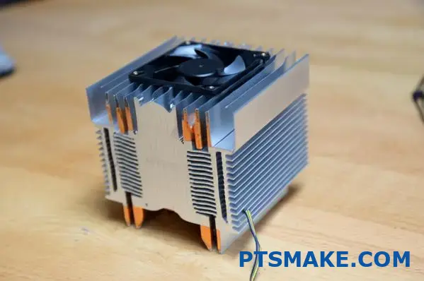
Active vs. Passive Cooling: When To Use Fans With Heat Sinks
Ever faced the frustrating dilemma of choosing between a bulky passive heat sink or adding fans to your design? This critical decision impacts not just thermal performance, but also your product’s noise level, reliability, and even its market success.
The choice between active and passive cooling for aluminum heat sinks fundamentally shapes your thermal management strategy. Understanding when to implement fans versus relying solely on passive solutions requires careful evaluation of thermal loads, space constraints, acoustic requirements, and power availability.
Understanding Active vs. Passive Cooling Fundamentals
Before diving into decision criteria, let’s clarify what distinguishes these two cooling approaches. Passive cooling relies entirely on natural convection and radiation to dissipate heat without moving parts. Active cooling, on the other hand, incorporates fans or blowers to force air movement across heat sink surfaces, dramatically improving heat transfer rates.
Thermal Performance Comparison
The most obvious difference between active and passive solutions is their thermal dissipation capability. This gap can be substantial:
| Cooling Method | Typical Thermal Resistance | Heat Dissipation Capacity | Space Efficiency |
|---|---|---|---|
| Passive Cooling | 1.5-8°C/W | Low-Medium | Low |
| Active Cooling | 0.2-1.5°C/W | Medium-High | High |
When designing cooling solutions at PTSMAKE, I’ve consistently observed that adding even a small fan can reduce thermal resistance by 60-80% compared to passive alternatives of similar size. This performance advantage becomes crucial when dealing with high-power components or space-constrained designs.
Evaluating Thermal Load Requirements
The primary factor driving the active versus passive decision is your system’s thermal load. This assessment must consider not just steady-state operation but also peak loads and thermal transients.
Heat Dissipation Thresholds
As a general guideline based on my experience with aluminum heat sinks:
- 0-15W: Passive cooling is typically sufficient and preferable
- 15-50W: Either approach may work depending on other constraints
- 50W+: Active cooling becomes increasingly necessary unless exceptional space is available
These thresholds aren’t absolute but serve as starting points. A compact device dissipating 30W may require active cooling, while a spacious enclosure might handle 75W passively with sufficient heat sink volume.
Thermal Density Considerations
Beyond raw wattage, the concentration of heat matters significantly. A 20W load concentrated in a 10mm² chip requires different cooling than the same power spread across a 100mm² surface. When thermal density exceeds approximately 1W/cm², active cooling typically becomes the more practical option.
Space Constraint Analysis
Available space often becomes the deciding factor between active and passive approaches. Passive solutions require substantial surface area and volume to match the performance of compact active systems.
Volumetric Efficiency
The space efficiency advantage of active cooling becomes clear when we examine the volume required for equivalent cooling:
- A passive aluminum heat sink might need 3-5 times the volume of an active solution to achieve similar thermal performance
- This volume differential increases as thermal loads rise
For products where compactness is valued (consumer electronics, portable devices, space-constrained installations), this efficiency often makes active cooling the only viable option despite other tradeoffs.
Form Factor Considerations
Beyond raw volume, the shape and orientation requirements differ significantly:
Passive heat sinks perform best with:
- Vertical fin orientation to optimize natural convection
- Wider fin spacing (typically 8-12mm) to allow air movement
- Unobstructed airflow paths above and below
Active heat sinks can function effectively with:
- Any orientation (though some are still optimal)
- Much tighter fin spacing (1.5-3mm)
- Directed airflow paths optimized for fan placement
At PTSMAKE, we’ve designed passive cooling solutions for clients who absolutely required them, but often found ourselves recommending significantly larger enclosures than initially planned to accommodate adequate heat dissipation.
Noise Considerations and Acoustic Requirements
Perhaps the most obvious advantage of passive cooling is silence. This factor alone can drive the decision for numerous applications where acoustic performance matters.
Noise-Sensitive Applications
Applications where passive cooling holds a decisive advantage include:
- Medical diagnostic equipment used in quiet examination rooms
- Audio recording and production equipment
- High-end home theater components
- Bedroom devices (media players, small form-factor PCs)
- Library and educational settings
For these scenarios, the acoustic benefit often outweighs the size penalty of passive solutions.
Fan Noise Mitigation Strategies
When active cooling is thermally necessary but noise is a concern, several strategies can help:
- Larger, slower fans move more air with less noise than smaller, faster alternatives
- PWM fan control allows dynamic speed adjustment based on actual thermal loads
- Vibration isolation mounting prevents fan vibrations from amplifying through the chassis
- Acoustic treatment of airflow paths can reduce turbulence noise
- Quality bearings in premium fans substantially reduce operating noise
Implementing these approaches at PTSMAKE has allowed us to develop active cooling solutions that remain below 25dBA – quiet enough for most environments while still delivering the thermal advantages of forced convection.
Power Availability and Energy Considerations
Active cooling requires power – an obvious but sometimes overlooked constraint, especially in portable or remote applications.
Power Budget Analysis
When evaluating active cooling, consider these power-related factors:
- Fan power consumption typically ranges from 0.5W to 5W depending on size and airflow
- Always factor in startup current which can be 2-3 times the running current
- Consider power supply noise sensitivity as fans can introduce ripple
- Evaluate backup/redundancy requirements for critical systems
For battery-powered devices, the continuous power draw of fans directly impacts runtime. One telecommunications client switched from active to passive cooling for their remote monitoring equipment, extending battery backup time by 22% – a critical improvement for their service reliability metrics.
Energy Efficiency Tradeoffs
In fixed installations, the energy consumption comparison becomes more nuanced:
- Active cooling consumes direct electricity for fan operation
- However, more efficient cooling can allow components to run cooler, potentially improving their efficiency
- For high-power systems, the improved cooling efficiency often outweighs the fan power consumption
The net energy balance depends greatly on the specific application and components involved.
Reliability and Maintenance Requirements
Reliability considerations often favor passive solutions, as fans introduce the only moving parts in many electronic systems.
Failure Mode Analysis
When evaluating cooling options, consider these reliability factors:
- Mean Time Between Failures (MTBF) for quality fans typically ranges from 50,000-200,000 hours
- Failure modes for fans include bearing wear, dust accumulation, and electrical failure
- Passive systems have no moving parts to fail but can still degrade through dust accumulation or corrosion
- System-level consequences of cooling failure should drive redundancy requirements
For mission-critical systems where maintenance access is limited or expensive, the inherent reliability advantage of passive cooling often outweighs performance benefits of active solutions.
Dust and Environmental Considerations
Environmental factors significantly impact the active vs. passive decision:
- Dust-heavy environments accelerate fan failure and reduce cooling efficiency
- Extreme temperatures affect fan reliability and bearing life
- Humidity and corrosive atmospheres can damage fan motors and electronics
- Vibration in industrial settings can accelerate fan bearing wear
In harsh environments, thermal redundancy6 becomes essential for active systems – designing the thermal solution to maintain acceptable (if degraded) performance even if fans fail.
Hybrid Approaches for Optimal Solutions
Rather than viewing active and passive cooling as binary choices, consider hybrid approaches that leverage the advantages of both:
- Passive cooling with active assistance: Design for adequate passive cooling under normal loads, with fans activating only during peak demands
- Redundant passive capacity: Implement active cooling for optimal performance but ensure sufficient passive capacity to prevent damage if fans fail
- Zoned cooling approaches: Use passive cooling for less critical components while targeting active cooling precisely where thermal density is highest
These hybrid strategies often deliver the best overall balance of performance, reliability, and efficiency.
In one medical imaging system we designed at PTSMAKE, we implemented a primarily passive cooling system supplemented by low-speed fans that activated only when internal temperatures exceeded specified thresholds. This approach provided silent operation during most diagnostic procedures while maintaining thermal protection during intensive scanning sequences.
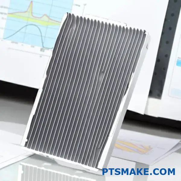
Thermal Interface Materials For Optimal Heat Transfer
Have you ever wondered why some electronics fail prematurely despite having top-quality cooling systems? The secret often lies in an invisible layer between components that many engineers overlook until it’s too late.
Thermal interface materials (TIMs) play a critical role in heat management by filling microscopic air gaps between heat-generating components and aluminum heat sinks. These specialized materials dramatically improve thermal conductivity, ensuring efficient heat transfer and preventing device failure due to overheating.
As someone who has managed countless thermal management projects at PTSMAKE, I’ve seen firsthand how the right thermal interface material can make the difference between a device that runs reliably for years and one that fails within months. Let me share insights from my experience about these essential but often overlooked components of effective cooling systems.
Understanding Thermal Interface Materials
Thermal interface materials serve a fundamental purpose: they eliminate air gaps between mating surfaces. Even perfectly machined surfaces have microscopic imperfections that trap air – a poor thermal conductor. TIMs fill these voids, creating a continuous thermal pathway from heat source to heat sink.
The Physics of Thermal Contact
When two solid surfaces meet, they typically only make actual contact at about 1-5% of their apparent contact area. The rest consists of microscopic air gaps that act as thermal insulators. This phenomenon creates a significant barrier to heat flow known as thermal contact resistance.
TIMs address this problem by:
- Filling microscopic air gaps with thermally conductive material
- Conforming to surface irregularities
- Creating a continuous heat transfer pathway
- Reducing thermal resistance at the interface
Key Performance Metrics
When selecting a thermal interface material, several properties determine its effectiveness:
| Property | Description | Importance |
|---|---|---|
| Thermal Conductivity | Rate at which heat passes through the material (W/m·K) | Primary indicator of heat transfer efficiency |
| Thermal Impedance | Overall resistance to heat transfer (°C·cm²/W) | More practical real-world performance metric |
| Bond Line Thickness | Thickness after application and compression | Thinner is generally better for thermal transfer |
| Conformability | Ability to fill surface irregularities | Critical for eliminating air gaps |
| Compression | Force required for optimal performance | Affects mounting requirements |
| Pump-Out Resistance | Ability to resist migration under thermal cycling | Important for long-term reliability |
Types of Thermal Interface Materials
A wide variety of thermal interface materials exist, each with distinct advantages for specific applications. Understanding their differences is essential for making the right selection.
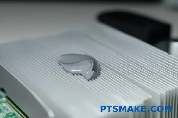
Thermal Greases and Pastes
Thermal greases (also called thermal pastes or compounds) were the first widely used TIMs and remain popular today.
Advantages:
- Excellent conformability to surface irregularities
- Achieve very thin bond lines (typically 0.001"-0.003")
- High thermal conductivity (1-10 W/m·K)
- No curing requirements
- Relatively low cost
Limitations:
- Prone to pump-out during thermal cycling
- Can dry out over time, reducing effectiveness
- Application can be messy and inconsistent
- Not ideal for vertical applications
At PTSMAKE, we’ve found thermal greases particularly effective for high-performance computing applications where achieving the thinnest possible interface layer is critical. For one server manufacturer, switching to a higher-grade thermal grease with better pump-out resistance reduced operating temperatures by 7°C and virtually eliminated thermal throttling issues.
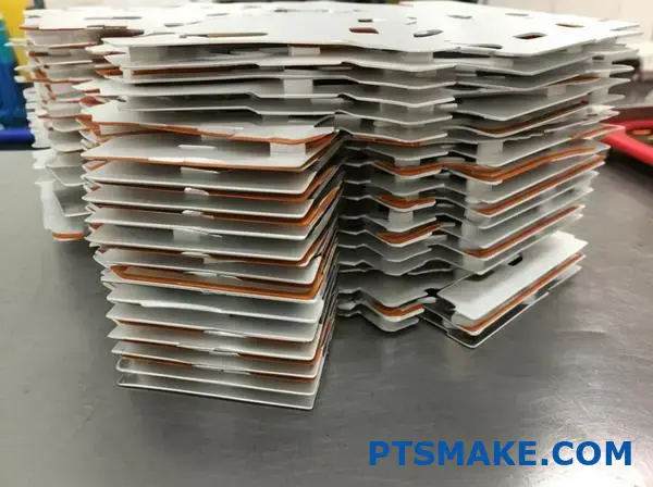
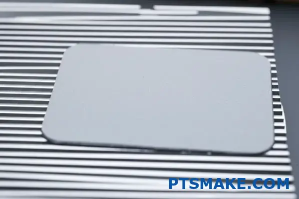
Thermal Pads and Gap Fillers
Thermal pads are pre-formed, solid sheets of compliant material that compress when mounted.
Advantages:
- Clean, pre-cut application
- Fill larger gaps (available in thicknesses from 0.5-10mm)
- Can bridge uneven surfaces or components of different heights
- Good electrical insulation properties
- Consistent performance
Limitations:
- Higher thermal resistance than premium greases
- Require more mounting pressure for optimal performance
- Less effective for microscopic surface irregularities
- More expensive than basic thermal greases
Thermal pads excel in mass-production environments where consistency and assembly speed are priorities. One consumer electronics client at PTSMAKE switched from grease to custom-cut thermal pads, reducing assembly time by 35% while maintaining comparable thermal performance.
Phase Change Materials
Phase change materials (PCMs) combine the best attributes of greases and pads, existing as solid films at room temperature but softening at operating temperatures.
Advantages:
- Solid at room temperature for clean handling
- Become semi-liquid at operating temperatures for excellent surface wetting
- Resist pump-out better than greases
- Achieve very thin bond lines
- Require minimal mounting pressure
Limitations:
- More expensive than basic thermal greases
- Temperature limitations (typically melt around 50-70°C)
- Can be brittle before phase change
- May require special handling
I’ve found PCMs particularly valuable for applications undergoing frequent thermal cycling. For a telecommunications equipment manufacturer, implementing phase change materials reduced mean time between failures by 27% in field-deployed equipment operating in variable temperature environments.
Metal-Based TIMs
For the most demanding thermal applications, metal-based TIMs offer superior performance.
Options include:
- Indium foils and alloys
- Solder thermal interfaces
- Liquid metal compounds
Advantages:
- Extremely high thermal conductivity (20-86 W/m·K)
- Excellent surface wetting
- Long-term stability
- Low thermal resistance
Limitations:
- Highest cost option
- Often electrically conductive (potential short circuit risk)
- Can cause galvanic corrosion with certain metals
- More complex application requirements
While expensive, metal-based TIMs offer unmatched performance for critical applications. In a high-power LED lighting project at PTSMAKE, using indium-based thermal interface material allowed passive cooling where conventional TIMs would have required active fan cooling, resulting in a more reliable, silent solution for architectural lighting applications.
Application-Specific Selection Considerations
Choosing the optimal thermal interface material requires considering various application-specific factors.
Heat Sink Material Compatibility
When using aluminum heat sinks, material compatibility becomes a key consideration:
- Chemical compatibility – Some TIMs contain additives that can accelerate corrosion in aluminum
- Galvanic compatibility – Metal-filled compounds can create galvanic cells with aluminum
- Coefficient of thermal expansion (CTE) – Materials should have compatible expansion rates to prevent interface degradation during thermal cycling
For aluminum heat sinks specifically, silicon-based thermal compounds typically offer the best balance of performance and long-term compatibility. Compounds containing silver particles should be evaluated carefully, as they can potentially accelerate corrosion in the presence of moisture.
Application and Operating Environment
Environmental factors significantly influence TIM selection:
- Temperature range – Some materials degrade or harden at temperature extremes
- Thermal cycling frequency – More frequent cycles increase pump-out risk
- Humidity levels – Can affect long-term stability of some materials
- Expected service life – Longer requirements favor more stable materials
- Vertical vs. horizontal mounting – Affects risk of material migration
- Serviceability requirements – Need for disassembly may favor certain materials
Pressure Considerations
Different TIMs require varying levels of mounting pressure to perform optimally:
- Thermal greases: Minimal pressure required (typically 10-30 PSI)
- Thermal pads: Moderate pressure required (typically 30-100 PSI)
- Phase change materials: Low to moderate pressure (typically 30-50 PSI)
- Metal-based TIMs: Variable, but often require precise pressure control
The available mounting solution often constrains TIM selection. Push pins provide relatively low pressure, making them suitable for greases but potentially suboptimal for thicker thermal pads. Screw mounting systems offer more flexibility in applying appropriate pressure for any TIM type.
Implementation Best Practices
Proper application is as important as material selection for achieving optimal thermal performance.
Application Methods
Each type of TIM has specific application requirements:
For thermal greases:
- Apply a thin, even layer using screen printing, dispensing, or the manual "X" pattern method
- Aim for complete coverage after compression with minimal squeeze-out
- Avoid air bubbles or voids during application
For thermal pads:
- Ensure correct size and thickness
- Remove protective films completely
- Apply to clean, dry surfaces
- Apply even pressure during mounting
For phase change materials:
- Handle carefully in solid state
- Ensure initial heat cycle reaches activation temperature
- Apply recommended mounting pressure
Common Implementation Mistakes
Through my work at PTSMAKE, I’ve observed several common mistakes in TIM implementation:
- Using too much material – "More is better" is a common misconception; excess material increases thermal resistance
- Uneven application – Creates hotspots and reduces overall efficiency
- Contaminated surfaces – Oils, fingerprints, and dust significantly reduce effectiveness
- Insufficient mounting pressure – Prevents optimal material distribution and contact
- Mixing incompatible materials – Can cause chemical reactions and degradation
Long-Term Reliability Considerations
For devices expected to operate for years without maintenance, long-term TIM behavior is critical:
- Dry-out risk – Some greases lose volatiles over time
- Pump-out effects – Material migration during thermal cycling
- Material degradation – Chemical breakdown from heat or environmental factors
- Interface separation – Physical separation due to vibration or CTE mismatches
The best TIM is one that maintains performance throughout the product’s expected lifetime, not just during initial testing. When designing cooling solutions for industrial equipment at PTSMAKE, we typically recommend slightly over-specifying thermal interface materials to accommodate some performance degradation over time while maintaining safe operating temperatures.
The right thermal interface material forms a crucial bridge between your heat-generating components and aluminum heat sink. By understanding the options, carefully evaluating application requirements, and implementing proper application techniques, you can dramatically improve thermal performance and ensure the long-term reliability of your electronic systems.
Learn how optimizing thermal gradients can reduce your cooling costs by up to 30%. ↩
Discover how enhanced conductivity can improve your device’s reliability and lifespan. ↩
Discover how these specialized materials can reduce device thickness while improving cooling efficiency. ↩
Learn how proper mounting prevents performance degradation over time through material settling and deformation. ↩
Learn how custom extrusion dies can be optimized for your specific cooling needs while controlling costs. ↩
Find advanced strategies for building redundancy into your cooling systems to prevent costly failures. ↩