Ever tried to drill a perfectly straight hole through metal, only to find it’s slightly off-center or not perfectly round? In precision manufacturing, even tiny inaccuracies can cause entire assemblies to fail, resulting in costly rework or scrapped parts.
Boring machining is a precision metalworking process that enlarges and finishes existing holes to achieve greater accuracy in diameter, roundness, and alignment than drilling alone can provide. It’s essential for parts requiring high precision in industries like aerospace, automotive, and medical equipment manufacturing.
As someone who works with precision machining every day, I can tell you that boring is one of those critical operations that often goes unnoticed until something goes wrong. While it might seem like a simple hole-making process, proper boring can be the difference between components that fit perfectly and those that fail during assembly. Let me walk you through what makes this process so important and how it works in modern manufacturing.
What Is The Process Of Boring Machining?
Have you ever struggled with achieving precise internal diameters in your machined parts? Or found yourself frustrated when holes don’t align perfectly across components? These common challenges can create serious downstream assembly problems and even cause entire projects to fail.
Boring machining is a precision metal-cutting process that enlarges and finishes existing holes to exact specifications using single-point cutting tools. Unlike drilling which creates holes, boring refines them by removing material from internal surfaces to achieve superior dimensional accuracy, surface finish, and concentricity.
Understanding Boring Machining Fundamentals
Boring is an essential metalworking process that I’ve seen transform countless projects requiring precise internal features. While it might seem similar to drilling at first glance, the differences are significant. Drilling creates initial holes, while boring improves existing ones.
In my experience working with clients at PTSMAKE, boring operations typically follow drilling, reaming, or punching processes. The main purposes of boring include:
- Improving dimensional accuracy of holes
- Enhancing surface finish quality
- Correcting hole alignment issues
- Creating precise concentric features
- Enlarging holes beyond standard drill sizes
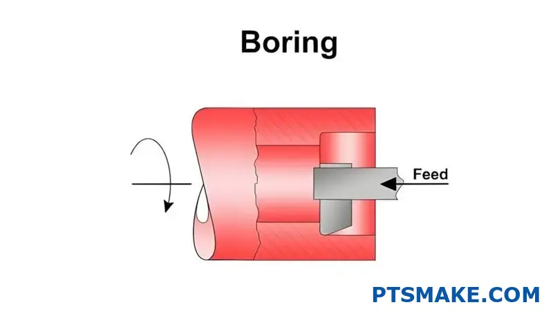
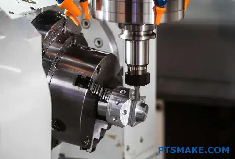
The boring process involves a cutting tool that rotates and moves along an axis to remove material from an internal cylindrical surface. What makes boring particularly valuable is its ability to create extraordinarily precise internal features that would be impossible to achieve with drilling alone.
Types of Boring Operations
Based on my manufacturing experience, boring operations can be categorized into several distinct types:
Line Boring
Line boring creates aligned holes across multiple surfaces or components. This operation is critical in engine blocks, transmission housings, and other assemblies where perfect alignment is essential for proper function.
Back Boring
Back boring accesses hard-to-reach surfaces from the reverse side of a workpiece. This technique proves invaluable when the front face of a part cannot be easily accessed or when creating counterbores and spotfaces on the back side of components.
Precision Boring
When tolerances must be extremely tight (often within ±0.0005 inches or less), precision boring is the technique of choice. This specialized operation uses fine adjustments and vibration-dampening tools to achieve exceptional accuracy.
Boring Tools and Equipment
The tools used in boring operations vary widely depending on the specific application:
Boring Heads
Boring heads are adjustable tools that allow for precise diameter control. They typically feature micrometer adjustments that can be set to remove specific amounts of material with each pass.
Boring Bars
These long, slender tools hold cutting inserts and extend into workpiece holes. They come in various configurations:
- Standard boring bars: Used for general-purpose applications
- Anti-vibration boring bars: Contain dampening mechanisms for deeper holes
- Micro-boring bars: Designed for very small diameter holes
Boring Machines
Several types of equipment can perform boring operations:
| Machine Type | Primary Applications | Key Features |
|---|---|---|
| Horizontal Boring Mills | Large workpieces, complex features | Movable spindle, rotary table |
| Vertical Boring Mills | Large diameter, short depth holes | Rotating table, fixed tools |
| Jig Borers | Ultra-precision work | Coordinate-based positioning |
| CNC Machining Centers | Flexible, automated boring | Programmable tool paths |
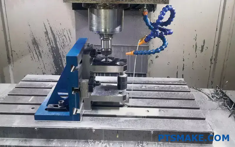
The Boring Process Step-by-Step
At PTSMAKE, our boring processes typically follow this sequence:
Workpiece Preparation: The part is secured firmly to prevent movement during machining.
Initial Hole Creation: A hole is drilled, punched, or cast to provide access for the boring tool.
Tool Setup: The boring bar or head is mounted and adjusted to the correct starting diameter.
Boring Operation: The tool rotates and advances into the workpiece, removing material in a controlled manner.
Measurement: The hole is measured to verify dimensional accuracy.
Final Passes: Additional light cuts may be made to achieve final specifications.
Surface Finishing: Sometimes secondary operations like honing or lapping follow boring to improve surface quality.
The key to successful boring is maintaining rigidity throughout the system. Any deflection1 in the tooling can lead to dimensional inaccuracies, poor surface finish, or even catastrophic tool failure.
Advantages and Limitations of Boring
In my years working with precision manufacturing, I’ve observed these key advantages of boring:
- Exceptional dimensional accuracy and geometric control
- Superior surface finish quality
- Ability to create specialized internal features
- Correction of hole misalignments
- Production of features beyond standard tool sizes
However, boring also has some limitations:
- Generally slower than drilling for initial hole creation
- Requires specialized tools and skilled operators
- Can be challenging for very deep holes due to tool deflection
- Higher cost compared to some alternative processes
Modern Innovations in Boring Technology
Today’s boring technology has evolved significantly. Modern CNC boring operations integrate advanced features like:
- Real-time measurement and feedback systems
- Vibration monitoring and active dampening
- Automated tool compensation for wear
- Multi-axis synchronized movements for complex geometries
At PTSMAKE, we’ve invested in these cutting-edge technologies to deliver consistently precise boring operations for our clients’ most demanding applications.
What Is The Advantage Of Boring Machine?
Have you ever struggled with achieving precise holes in metal parts? Or found yourself frustrated when dimensions aren’t consistent across multiple pieces? Many engineers face these challenges daily, often resorting to less efficient methods that compromise quality.
A boring machine offers significant advantages including enhanced precision, versatility, and efficiency. Unlike drilling, boring can enlarge and finish existing holes with exceptional accuracy, maintain tight tolerances, reduce tool deflection, and create perfectly cylindrical holes even in hard materials.
Understanding Boring Machines
Boring is a machining process that enlarges and finishes holes with high precision. Unlike drilling which creates initial holes, boring refines existing holes to exact specifications. After working with various machining processes for over 15+ years, I’ve found boring machines to be indispensable for precision manufacturing.
Types of Boring Machines
There are several types of boring machines, each designed for specific applications:
Horizontal Boring Machines: These are versatile and commonly used for large workpieces. At PTSMAKE, we use horizontal boring machines for complex parts that need multiple operations without repositioning.
Vertical Boring Machines: Ideal for large, circular workpieces. Think of them as vertical lathes where the workpiece rotates around a vertical axis.
Jig Boring Machines: When extreme precision is needed, jig boring machines are the go-to solution. They can achieve tolerances as tight as ±0.0001 inches.
CNC Boring Machines: Modern CNC boring machines combine precision with automation, allowing for complex boring operations with minimal human intervention.
Key Advantages of Boring Machines
Unmatched Precision
The primary advantage of boring machines is their ability to achieve exceptional precision. When working with critical components like engine cylinders or aerospace parts, even minor deviations can cause significant problems.
Boring machines can maintain concentricity2 between different hole sections, something nearly impossible with other machining methods. In a recent aerospace project at PTSMAKE, we maintained tolerances of ±0.0005 inches across multiple boring operations—a level of precision that directly impacts the performance and safety of the final product.
Superior Surface Finish
Boring operations typically produce excellent surface finishes, often eliminating the need for additional finishing operations. The controlled cutting action of boring tools results in smoother surfaces compared to drilling.
The surface finish quality is measured in Ra (Roughness average) values, and boring can achieve much lower Ra values than drilling:
| Machining Process | Typical Ra Value (μin) | Surface Quality |
|---|---|---|
| Standard Drilling | 63-125 | Fair |
| Precision Boring | 16-32 | Very Good |
| Fine Boring | 4-16 | Excellent |
This superior finish is particularly important for applications where fluid flow, sealing, or bearing fits are critical.
Versatility in Operations
Modern boring machines, especially CNC models, offer remarkable versatility. They can perform multiple operations including:
- Straight boring
- Tapered boring
- Facing
- Grooving
- Threading
- Step boring
This versatility reduces the need to transfer workpieces between different machines, minimizing setup time and potential alignment errors. At PTSMAKE, we’ve integrated these capabilities to reduce production time by up to 40% on complex parts.
Cost Efficiency for Production Runs
While the initial investment in a quality boring machine is substantial, the long-term benefits often outweigh the costs, especially for production runs. Here’s why:
- Reduced Scrap Rates: The precision of boring machines significantly reduces rejected parts.
- Faster Production: Combine multiple operations in a single setup.
- Consistency: Maintain tight tolerances across large production runs.
- Less Manual Intervention: Reduce labor costs through automation.
For one of our automotive clients, switching to CNC boring from conventional methods reduced overall production costs by 27% while improving quality metrics.
Practical Applications
Boring machines excel in several industries:
- Automotive: Engine blocks, cylinder heads, transmission components
- Aerospace: Turbine housings, landing gear components, structural elements
- Energy: Valve bodies, pump housings, turbine components
- General Manufacturing: Precision housings, mold bases, fixture components
The greatest value comes when dealing with high-value materials where mistakes are costly. I recall a titanium component project where each raw material blank cost over $1,200. Using our precision boring capabilities ensured zero scrap rate, saving tens of thousands in potential material losses.
Limitations to Consider
Despite their advantages, boring machines aren’t always the best choice:
- High initial investment costs
- Require skilled operators for setup and programming
- Not economical for very small production runs or simple holes
- Take up significant floor space compared to simpler drilling equipment
For smaller shops or those with limited precision requirements, the investment might be hard to justify. However, working with a manufacturing partner like PTSMAKE that already has these capabilities can provide access to the technology without the capital investment.
Milling vs. Boring: How Do These Processes Compare in Modern Manufacturing?
Have you ever stood watching a CNC machine at work and wondered exactly what operation was happening? Or perhaps you’ve received a quote for your parts that mentioned both milling and boring operations, leaving you confused about why you need both and what makes them different?
Milling and boring are distinct machining processes with different purposes and capabilities. Milling uses rotating multi-point cutting tools to remove material from the workpiece surface, while boring employs single-point tools to enlarge and finish existing holes with high precision and improved concentricity.
Key Differences Between Milling and Boring
When examining milling and boring processes, several fundamental differences become apparent. These distinctions affect everything from tool selection to the applications where each process excels.
Tool Configuration and Movement
Milling operations use multi-point cutting tools that rotate around their own axis. As the tool rotates, its multiple cutting edges remove material from the workpiece. The cutting action in milling can occur in various directions, allowing for versatile material removal.
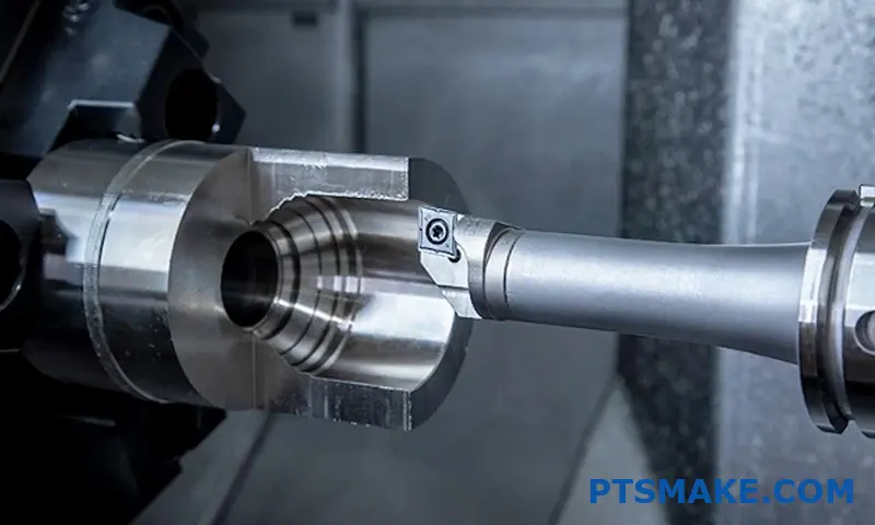
Boring, on the other hand, uses a single-point cutting tool. This tool extends from a boring bar and removes material from the inside surface of an existing hole. The boring bar rotates around its axis while the cutting tip engages with the workpiece material.
Primary Applications and Capabilities
Milling shines in creating complex external features and contours. At PTSMAKE, we utilize milling for:
- Creating flat surfaces
- Cutting slots and keyways
- Machining complex 3D contours
- Producing external threads
- Generating gears and splines
Boring specializes in hole-related operations, particularly when precision is critical. We employ boring when:
- Enlarging existing holes to precise diameters
- Improving hole concentricity
- Creating stepped holes with multiple diameters
- Achieving superior surface finish inside holes
- Establishing precise hole location relationships
Accuracy and Surface Finish Considerations
When comparing accuracy between these processes, boring generally provides higher precision for hole dimensions. This is because the single-point cutting tool can be controlled more precisely and adjusted in very small increments.
The runout3 in milling tools can sometimes limit the ultimate precision, especially with longer tools or when machining deep features. Boring, with its simpler cutting action, can often achieve tighter tolerances for hole diameters.
Material Removal Efficiency
Milling typically offers higher material removal rates than boring. The multiple cutting edges on milling tools allow for more aggressive cutting parameters. This makes milling the preferred choice for bulk material removal.
Boring is more focused on precision than speed. It’s often employed as a finishing operation after drilling or rough boring has established the basic hole. The table below summarizes these efficiency differences:
| Process | Material Removal Rate | Typical Applications | Tool Wear |
|---|---|---|---|
| Milling | High | Roughing, general machining | Moderate to high |
| Boring | Low to moderate | Finishing, precision holes | Low to moderate |
When to Choose Milling vs. Boring
Selecting between milling and boring depends on several factors including the part requirements and manufacturing constraints.
Feature Type Requirements
The most obvious decision factor is the type of feature needed:
- Choose milling for external features, pockets, and complex contours
- Select boring for precise internal hole features, especially when concentricity and surface finish are critical
In my experience at PTSMAKE, we often use both processes on the same part. We might mill an external profile and then bore precise mounting holes that need to maintain tight positional tolerances.
Tolerance and Surface Finish Specifications
When engineering drawings specify particularly tight tolerances for hole diameters (often under ±0.001"), boring is typically the better choice. The controlled, single-point cutting action allows for very precise diameter control.
For surface finish requirements, boring can achieve excellent results inside holes. Milling surface finishes can vary more widely depending on the tool, parameters, and machine rigidity.
Cost and Production Volume Considerations
Cost factors also influence this decision:
- Milling is generally more efficient for bulk material removal
- Boring tools can be more specialized and thus more expensive
- Production volume affects setup costs vs. per-part costs
For high-volume production at PTSMAKE, we often invest in specialized boring tools that can maintain tight tolerances over thousands of parts. For lower volumes, we might adapt milling strategies to minimize tooling costs.
Combining Milling and Boring for Optimal Results
The most effective manufacturing strategies often combine both processes strategically:
- Use milling for initial material removal and establishing basic features
- Follow with boring operations for holes requiring high precision
- Consider the entire process chain when planning machining operations
This combined approach leverages the strengths of each process while minimizing their limitations. I’ve found this strategy particularly effective when producing complex components with both external features and precision holes.
What Is The Difference Between Boring And Fine Boring?
Have you ever found yourself confused when your machinist starts talking about boring versus fine boring operations? Or perhaps wondered why a supposedly "bored" hole doesn’t meet your precision requirements? The subtle differences between these similar-sounding processes can lead to costly misunderstandings and project delays.
Boring and fine boring are both hole-enlarging processes, but fine boring delivers superior accuracy and surface finish. Standard boring typically achieves tolerances of ±0.05mm, while fine boring can reach ±0.01mm or better with significantly smoother surfaces, making it ideal for high-precision applications.
Understanding Basic Boring Operations
Boring is a machining process used to enlarge an existing hole to a specified diameter and finish. Unlike drilling, which creates holes from solid material, boring refines pre-existing holes. At PTSMAKE, we use boring operations daily for components requiring precise internal diameters.
The basic boring process involves a single-point cutting tool that moves parallel to the workpiece’s axis of rotation. The cutting edge removes material from the internal surface of the hole, gradually enlarging it to the desired dimensions. This process is particularly valuable when working with irregular or off-center existing holes that need correction.
Standard boring operations typically achieve tolerances in the range of ±0.05mm to ±0.02mm, depending on the machine capabilities and setup. The surface finish generally falls between 1.6 to 3.2 micrometers Ra (roughness average).
Fine Boring: Taking Precision to the Next Level
Fine boring represents a specialized advancement of the standard boring process. When clients approach us with stringent accuracy requirements4 for critical components, fine boring becomes our go-to solution.
Fine boring employs specialized tools and more controlled cutting parameters to achieve superior precision. The cutting tools used in fine boring typically feature more refined cutting edges, often with special geometries designed to minimize vibration and maximize dimensional stability.
The key differences I observe between standard and fine boring include:
Accuracy and Tolerance Capabilities
Fine boring can achieve tolerances as tight as ±0.005mm to ±0.01mm, making it roughly 2-10 times more precise than standard boring. This level of accuracy is crucial for components like hydraulic valve bodies, engine cylinders, and precision bearings where even micro-deviations can affect performance.
Surface Finish Quality
While standard boring produces acceptable surface finishes for many applications, fine boring can deliver surface finishes as smooth as 0.4 to 0.8 micrometers Ra. This exceptional smoothness reduces friction in moving parts and enhances sealing capabilities in hydraulic components.
Equipment and Tooling Requirements
| Aspect | Standard Boring | Fine Boring |
|---|---|---|
| Machine Rigidity | Moderate | Very High |
| Tool Materials | HSS, Carbide | Premium Carbide, Cermet, PCD |
| Coolant Requirements | Standard | Precise Temperature Control |
| Cutting Speed | Standard | Lower, More Controlled |
| Feed Rate | Standard | Finer, More Precise |
Process Control Factors
Fine boring requires stricter control of machining parameters. Temperature stability becomes crucial as even minor thermal expansions can affect the final dimensions. At PTSMAKE, our fine boring operations include:
- Pre-operation thermal stabilization of workpieces
- More frequent tool inspections and adjustments
- Enhanced vibration monitoring and dampening systems
- Multiple light finishing passes rather than one heavier cut
Practical Applications: When to Choose Fine Boring
Based on my experience working with various industries, here are situations where fine boring proves to be the optimal choice:
Critical Mating Components
Components that must fit together with minimal clearance, such as precision valve assemblies or bearing housings, benefit significantly from fine boring. The enhanced dimensional accuracy ensures consistent performance and extended service life.
High-Performance Applications
Aerospace, automotive racing, and medical device industries often require fine-bored components to achieve optimal performance. The superior surface finish reduces friction and wear while enhancing efficiency.
Cost-Benefit Considerations
While fine boring does involve higher processing costs due to longer machining times and specialized tooling, it often provides substantial value through:
- Reduced assembly time and issues
- Extended component lifespan
- Improved product performance
- Decreased warranty claims and failures
Combining Technology with Traditional Techniques
Modern manufacturing has introduced innovative approaches to fine boring. Computer Numerical Control (CNC) machines now incorporate adaptive control systems that can adjust the boring parameters in real-time based on feedback from monitoring systems.
At PTSMAKE, we’ve integrated these technologies with traditional craftsmanship. Our machinists combine decades of hands-on experience with advanced measurement systems to achieve repeatable precision that meets or exceeds client expectations.
For particularly challenging applications, we sometimes employ hybrid approaches, using standard boring for initial material removal followed by fine boring for the final dimensions and surface finish. This balance of efficiency and precision helps us deliver high-quality components while maintaining competitive pricing.
How To Reduce Ovality In Boring Operation?
Ever struggled with parts that just won’t fit because they’re slightly oval instead of perfectly round? Have you spent hours trying to troubleshoot boring operations only to find your tolerance requirements slipping away with each pass? Ovality can be a persistent headache that compromises precision and functionality.
Reducing ovality in boring operations requires a systematic approach: stabilize the workpiece, use proper tooling with appropriate geometry, maintain optimal cutting parameters, consider tool path strategies, and implement regular monitoring. Each factor must be carefully controlled to achieve cylindrical accuracy.
Understanding the Root Causes of Ovality
Ovality, also called out-of-roundness, is a common geometric defect in boring operations where the cross-section of a hole deviates from a perfect circle. Before implementing solutions, it’s crucial to understand what causes this problem in the first place.
Mechanical Causes
The most common mechanical factors contributing to ovality include:
- Insufficient workpiece rigidity – When the workpiece flexes during machining
- Tool deflection – Cutting forces causing the boring bar to bend
- Machine vibration – Both from the machine itself and the cutting process
- Imbalanced holding fixtures – Creating uneven pressure on the workpiece
I’ve seen countless boring operations fail simply because the fundamentals of mechanical stability weren’t properly addressed. At PTSMAKE, we always begin troubleshooting ovality issues by examining the mechanical setup before considering any other factors.
Process Parameters
Even with perfect mechanical setup, improper cutting parameters can introduce ovality:
| Parameter | Effect on Ovality | Recommended Approach |
|---|---|---|
| Cutting Speed | High speeds can increase vibration | Reduce speed for longer boring bars |
| Feed Rate | Excessive feeds cause deflection | Use conservative feeds, especially for finish passes |
| Depth of Cut | Large cuts create higher forces | Multiple light cuts for final sizing |
| Coolant Application | Inconsistent cooling causes thermal distortion | Ensure steady, adequate coolant flow |
Tooling Considerations
The boring bar itself plays a critical role in controlling ovality. The L/D ratio5 (length-to-diameter) is particularly important – as this ratio increases, rigidity decreases exponentially. In my experience, keeping this ratio below 6:1 with standard tools helps maintain acceptable roundness.
Practical Solutions to Minimize Ovality
Based on my work with precision components, here are the most effective approaches to reduce ovality:
1. Optimize Workholding Strategy
Proper workholding is your first defense against ovality:
- Use 3-jaw chucks with soft jaws for custom-machined contact surfaces
- Apply even clamping pressure to prevent distortion
- Consider thermal effects – allow parts to reach thermal equilibrium before final boring
- Maximize contact area between the workpiece and holding device
For particularly challenging thin-walled components, consider using expanding mandrels or specialized fixtures that support the part uniformly.
2. Select Appropriate Boring Tools
Tool selection dramatically impacts your ability to achieve round bores:
- Anti-vibration boring bars with internal damping mechanisms
- Carbide-shank boring bars offering 3x the rigidity of steel for the same L/D ratio
- Balanced tool assemblies to minimize harmonic vibration
- Positive geometry inserts to reduce cutting forces
When working with larger diameter bores, modular boring systems with multiple cutting edges can help distribute cutting forces more evenly.
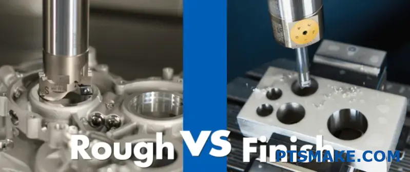
3. Implement Strategic Machining Approaches
The machining strategy itself can compensate for tendencies toward ovality:
- Roughing and finishing passes – remove the bulk of material first, then take light finishing cuts
- Climb vs. conventional cutting – test both approaches as results can vary by application
- Helical interpolation for smaller holes when appropriate
- Multiple spring passes at the same diameter to "polish" the bore
4. Utilize Advanced Monitoring Techniques
Real-time monitoring can help catch ovality issues before they become problems:
- In-process gauging when possible
- Vibration monitoring systems to alert operators to conditions that may cause ovality
- Regular inspection intervals during production runs
- Statistical process control to identify trends before they cause rejects
Case Study: Solving Ovality in Precision Hydraulic Components
At PTSMAKE, we recently faced a challenging ovality issue with hydraulic valve bodies requiring roundness tolerances of 0.005mm. Initial production showed inconsistent results with ovality up to 0.02mm. After systematic analysis, we implemented these solutions:
- Replaced standard boring bars with carbide-shanked vibration-dampening alternatives
- Modified the fixture design to provide better support around the bore area
- Adjusted cutting parameters to include multiple spring passes at final diameter
- Implemented in-process air gauging to monitor results
The result was consistent roundness within 0.003mm, exceeding customer requirements and improving assembly fit and function.
How To Choose The Right Boring Tool For Specific Materials?
Have you ever found yourself staring at a selection of boring tools, unsure which one will give you the perfect finish on your specific material? Or worse, have you experienced the frustration of a ruined workpiece because your boring tool couldn’t handle the material properties?
Choosing the right boring tool for specific materials requires matching tool material, geometry, and coating to the workpiece’s hardness, composition, and required surface finish. For softer materials like aluminum, use sharp, polished HSS tools; for hardened steels, select carbide tools with specialized coatings to ensure optimal performance and longevity.
Understanding Material Properties and Their Impact on Boring Tool Selection
When selecting a boring tool, the material you’re working with is the primary consideration. Different materials have unique characteristics that directly affect how they respond to machining processes. The hardness, ductility, thermal conductivity, and metallurgical structure6 of your workpiece material determine which boring tool will provide optimal results.
In my experience at PTSMAKE, I’ve found that matching the tool to the material isn’t just about getting the job done—it’s about getting it done efficiently with the highest possible quality. Let’s explore how various material properties influence boring tool selection:
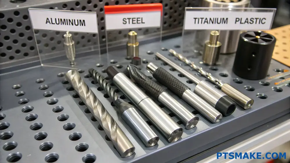
Material Hardness and Tool Material Compatibility
The hardness of your workpiece material dictates the boring tool material you should use:
| Workpiece Material Hardness | Recommended Tool Material | Benefits |
|---|---|---|
| Soft (Aluminum, Brass) | High-Speed Steel (HSS) | Economical, sharp cutting edges |
| Medium (Carbon Steel) | Cobalt-enriched HSS, Carbide | Better wear resistance, higher cutting speeds |
| Hard (Hardened Steel, Inconel) | Carbide, Ceramic, CBN | Superior hardness and heat resistance |
| Very Hard (Hardened Tool Steel) | PCBN, PCD | Extreme wear resistance, long tool life |
When working with softer materials like aluminum, I’ve found that HSS tools with polished flutes can provide excellent chip evacuation and surface finish. For tougher materials, carbide tools with appropriate coatings have proven indispensable.
Thermal Properties and Cooling Considerations
Materials with poor thermal conductivity, like stainless steel and titanium, tend to retain heat in the cutting zone. This can lead to:
- Accelerated tool wear
- Workpiece thermal expansion
- Built-up edge formation
- Poor surface finish
For these materials, I recommend boring tools with:
- Internal coolant delivery systems
- Specialized coatings (TiAlN, AlTiN) that provide thermal barriers
- Geometry designed for lower heat generation
When we machine titanium components at PTSMAKE, we always select tools with these features to ensure consistent quality.
Boring Tool Geometry for Specific Materials
The cutting geometry of a boring tool significantly impacts its performance on different materials. Here’s how to match boring tool geometries to specific materials:
Rake Angle Selection
Tool rake angle should be selected based on material ductility:
- High Positive Rake (15-20°): Ideal for soft, ductile materials like aluminum and copper. Reduces cutting forces and heat generation.
- Moderate Rake (5-15°): Well-suited for medium-hardness materials like carbon steels and cast iron.
- Neutral to Negative Rake (0 to -5°): Best for hardened materials, providing tool edge strength at the expense of higher cutting forces.
Edge Preparation Considerations
The edge preparation of your boring tool is crucial for optimal performance:
- Sharp Edges: Essential for soft, gummy materials to prevent built-up edge formation
- Light Hone (T-land): Provides stability for medium-hardness materials
- Chamfered Edges: Strengthens the cutting edge for interrupted cuts in hard materials
I’ve found that for precision boring operations in aluminum at PTSMAKE, a single-point boring tool with a sharp edge and polished surface produces the best surface finish, while for hardened steels, a multi-point tool with chamfered edges ensures better stability and tool life.
Coating Technologies for Enhanced Performance
Modern coating technologies have revolutionized the performance of boring tools across different materials:
| Coating Type | Best For Materials | Key Benefits |
|---|---|---|
| TiN (Titanium Nitride) | General purpose, steels | Improved hardness, reduced friction |
| TiCN (Titanium Carbonitride) | Carbon steels, cast iron | Better wear resistance than TiN |
| TiAlN/AlTiN | High-temp alloys, hardened steels | Superior heat resistance, oxidation protection |
| Diamond (PCD) | Non-ferrous metals, composites | Exceptional wear resistance, thermal conductivity |
| nACo® | Hardened steels, difficult alloys | Nano-composite structure, extreme hardness |
In our precision machining operations, I’ve seen coating selection make a dramatic difference in tool life and part quality, especially when boring deep holes in difficult materials.
Application-Specific Recommendations
Based on my experience with various materials, here are some specific recommendations:
Aluminum and Non-Ferrous Alloys
- Use PCD or polished carbide tools
- High positive rake angles (15-20°)
- Higher cutting speeds (300-1000 m/min)
- Light honing on cutting edges
Carbon and Alloy Steels
- TiAlN coated carbide tools
- Moderate rake angles (5-10°)
- Medium cutting speeds (100-300 m/min)
- Consider chip breaker geometry for chip control
Stainless Steels
- AlTiN coated carbide tools
- Positive rake angles (5-15°)
- Lower cutting speeds (60-150 m/min)
- Tools with enhanced edge strength
Hardened Materials (>45 HRC)
- CBN or ceramic tools
- Negative rake angles (0 to -5°)
- Appropriate cutting speeds based on tool material
- Rigid setup with minimal overhang
The right boring tool selection can mean the difference between a struggling operation and a smooth, efficient process that delivers exceptional results. At PTSMAKE, we continuously test and evaluate boring tools across different materials to ensure we’re using the optimal combination for each application.
What Are Common Defects In Boring Operations And How To Prevent Them?
Have you ever finished a boring operation only to discover surface irregularities, dimensional inaccuracies, or tool marks that ruin your entire workpiece? These frustrating defects not only waste valuable materials but also cause project delays and increased production costs.
Boring operations commonly suffer from defects like chatter, tapered holes, poor surface finish, and misalignment. These issues typically stem from improper tool selection, inadequate setup, unsuitable cutting parameters, or machine limitations. Prevention requires proper tool selection, rigid workholding, optimal cutting parameters, and regular equipment maintenance.
Common Defects in Boring Operations
Boring operations, despite their precision-oriented nature, often encounter several defects that can compromise the quality of the finished component. After working with countless manufacturing clients at PTSMAKE, I’ve identified several recurring issues that plague boring operations.
1. Surface Finish Problems
Poor surface finish is among the most common defects in boring operations. This manifests as scratches, feed marks, or an overall rough texture that doesn’t meet specifications. The primary causes include:
- Dull cutting edges unable to cleanly shear the material
- Improper feed rates creating visible feed marks
- Inadequate cutting fluid application leading to built-up edge formation
- Vibration and chatter transferring to the workpiece surface
In precision applications, especially for components in the medical or aerospace sectors, surface finish requirements can be extremely stringent. When working with materials like stainless steel or titanium, achieving the desired surface quality becomes even more challenging.
2. Dimensional Inaccuracies
Boring operations often struggle with dimensional precision issues, including:
- Oversized or undersized holes
- Cylindricity7 errors where the hole isn’t perfectly round
- Tapered holes rather than straight cylindrical bores
- Bell-mouthing or barrel-shape defects
These issues typically result from tool deflection, thermal expansion during machining, inadequate rigidity in the setup, or incorrect tool geometry. At PTSMAKE, we’ve implemented rigorous measurement protocols to catch these issues early in the production process.
3. Chatter and Vibration Marks
Chatter marks are wavy patterns on the bored surface caused by vibration during the cutting process. These vibrations create an unstable cutting condition that leaves distinctive marks on the workpiece. Common causes include:
| Cause | Description | Prevention Method |
|---|---|---|
| Excessive tool overhang | Long boring bars tend to vibrate more | Use shortest possible boring bar |
| Inadequate toolholder rigidity | Loose connections amplify vibrations | Ensure secure clamping and consider specialized anti-vibration holders |
| Unsuitable cutting parameters | High speeds with light cuts often induce chatter | Adjust speed/feed ratio for more stable cutting |
| Machine condition | Worn bearings or loose components | Regular machine maintenance |
When boring deep holes or working with long boring bars, managing these vibrations becomes especially critical. I’ve found that anti-vibration boring bars with internal damping mechanisms can make a significant difference in these challenging applications.
4. Positional Errors
Accurate positioning of bored holes is crucial, particularly in complex components where multiple features must align. Common positional defects include:
- Misalignment relative to other features
- Concentricity errors in multi-diameter bores
- Perpendicularity issues where the bore isn’t square to the reference surface
These errors typically stem from improper setup, inaccurate fixturing, or machine alignment issues. In high-precision work, even small temperature fluctuations in the shop environment can contribute to positional errors.
Prevention Strategies for Boring Defects
Having identified the common defects, let’s explore proven strategies to prevent them. These approaches have consistently delivered superior results across various industries we serve at PTSMAKE.
Proper Tool Selection and Setup
The foundation of defect-free boring starts with appropriate tooling:
- Select the correct boring bar material and design for your application
- Consider the length-to-diameter ratio (minimize overhang when possible)
- Use vibration-dampening tools for challenging setups
- Ensure proper insert geometry and grade for the workpiece material
For critical boring operations, I recommend carbide boring bars for shorter operations and composite or dampened steel bars for deeper bores. The additional cost of premium tooling quickly pays for itself through reduced defects and rework.
Optimized Cutting Parameters
Fine-tuning your cutting parameters is essential for defect prevention:
- Start with conservative speeds and feeds, then optimize
- Consider climb boring versus conventional boring for different materials
- Adjust depth of cut based on material properties and setup rigidity
- Implement consistent and appropriate cutting fluid application
The goal is to find the sweet spot where material removal rate is maximized without inducing defects. This often requires experience and sometimes trial runs on non-critical features.
Enhanced Workholding Strategies
Rigid workholding minimizes vibration and ensures positional accuracy:
- Use the most rigid workholding method practical for the operation
- Ensure proper support for thin-walled workpieces
- Eliminate stacked fixtures that can introduce flexibility
- Consider thermal effects in precision applications
At PTSMAKE, we’ve developed specialized fixturing solutions for boring operations that maintain rigidity while allowing for efficient part loading and unloading in production environments.
Advanced Monitoring and Measurement
Implementing in-process monitoring can catch defects before they become costly problems:
- Use acoustic or vibration sensors to detect chatter onset
- Implement in-process gauging where possible
- Establish statistical process control for critical boring operations
- Conduct regular capability studies to understand process limitations
These approaches allow for real-time adjustments before defects occur, significantly reducing scrap rates and improving overall quality.
How Does Boring Machining Impact Production Costs For Custom Parts?
Have you ever received a quote for custom machined parts with boring operations and wondered why the price seemed higher than expected? Or perhaps you’ve struggled to understand how different machining operations affect your bottom line when planning production budgets?
Boring machining significantly impacts production costs for custom parts through multiple factors including setup time, tooling expenses, precision requirements, and machine hourly rates. While initially appearing more expensive than basic operations, boring can actually reduce overall costs by improving part quality, minimizing secondary operations, and extending part longevity.
Understanding Boring Machining and Its Cost Structure
Boring is a precision machining process used to enlarge existing holes to exact specifications. Unlike drilling which creates new holes, boring refines and improves existing ones. In my experience working with thousands of custom parts at PTSMAKE, boring operations often represent a significant portion of machining costs, yet many engineers and procurement professionals don’t fully understand why.
The cost structure of boring operations consists of several key components:
Equipment Investment and Hourly Rates
Precision boring requires specialized equipment that commands higher hourly rates than standard machining centers. The machines capable of high-precision boring often cost:
| Machine Type | Approximate Cost | Typical Hourly Rate |
|---|---|---|
| Standard CNC Mill | $75,000-150,000 | $45-75/hour |
| Precision Boring Machine | $150,000-500,000 | $85-150/hour |
| Jig Boring Equipment | $300,000-800,000 | $120-200/hour |
These higher hourly rates directly impact your part costs, especially for tight-tolerance boring operations that may require the most expensive equipment.
Tooling Costs and Considerations
Boring tools themselves can be a significant cost factor. High-precision boring heads, inserts, and boring bars8 require substantial investment:
- Single-point boring tools: $100-500 each
- Adjustable boring heads: $500-3,000 each
- Precision insert systems: $200-800 plus $20-50 per insert
What many customers don’t realize is that specialized boring operations often require custom tooling setups that can’t be amortized across multiple jobs, meaning your specific project bears the full tooling cost.
Setup Time and Technical Expertise
Setup time for boring operations typically exceeds that of standard machining processes. At PTSMAKE, we’ve found that boring setups can take 1.5-3 times longer than standard milling or turning operations due to:
- Precise alignment requirements
- Tool length offset measurements
- Runout verification procedures
- Test cuts and verification
This additional setup time directly translates to higher costs, as the machine and operator time must be accounted for before the first chip is even cut.
Cost-Saving Opportunities in Boring Operations
Despite the higher upfront costs, boring operations can actually help reduce overall production costs when properly implemented:
Tolerance Improvements and Scrap Reduction
Precision boring can achieve tolerances as tight as ±0.0005" (0.0127mm), which significantly reduces scrap rates for critical components. In our production facility, implementing precision boring rather than drilling and reaming has reduced scrap rates by 15-25% for complex hydraulic components.
Eliminating Secondary Operations
By achieving precise dimensions and superior surface finishes in a single setup, boring can eliminate costly secondary operations:
| Operation | Typical Cost | Can Boring Eliminate? |
|---|---|---|
| Honing | $25-75 per part | Often yes |
| Grinding | $35-100 per part | Frequently |
| Hand Finishing | $20-60 per hour | Usually |
| Additional Setups | $50-200 per setup | Almost always |
For a production run of 1,000 parts, eliminating just one secondary operation worth $30 per part represents a $30,000 savings—often more than offsetting the higher boring costs.
Extended Tool Life Strategies
I’ve implemented several strategies at PTSMAKE to extend boring tool life and reduce costs:
- Using modular boring systems that allow quick insert changes rather than complete tool replacement
- Implementing proper cutting parameters based on material-specific data rather than generic recommendations
- Utilizing appropriate coolant delivery methods to extend tool life by 30-50%
- Developing toolpath strategies that distribute wear evenly across cutting edges
These approaches have consistently resulted in 25-40% reductions in tooling costs for our boring operations.
Balancing Precision and Cost in Production Planning
When planning production that includes boring operations, I recommend considering these cost-optimization approaches:
- Evaluate whether all bored features truly require high precision, as relaxing non-critical tolerances can significantly reduce costs
- Consider designing parts to minimize the number of boring operations required
- Group similar boring operations across multiple parts to reduce setup costs
- Analyze whether alternative processes like reaming might be sufficient for some applications
- Determine if modern CNC mills with high-precision capabilities can perform boring operations adequately without requiring specialized boring equipment
By carefully analyzing these factors for each production run, you can often reduce boring-related costs by 15-30% without compromising part quality.
The Long-Term Cost Equation of Precision Boring
While the immediate costs of boring operations appear higher, the long-term value often outweighs these expenses:
- Precision-bored components typically have 20-40% longer operational lifespans
- Assembly time can be reduced by 15-25% when components have precise bored features
- Warranty claims and field failures decrease significantly with properly bored components
In one automotive application we handled at PTSMAKE, increasing our boring precision added $12 per part to production costs but reduced warranty claims by over $45 per unit shipped—representing a substantial net savings for our client.
What Are The Best Practices For Maintaining Boring Machine Accuracy?
Ever struggled with boring machines producing out-of-spec parts despite your best setup efforts? Have you faced the frustration of recalibrating your boring equipment repeatedly, watching production schedules slip away while precision continues to drift?
Maintaining boring machine accuracy requires consistent calibration, proper thermal management, regular inspection of wear components, vibration control, and implementing robust preventive maintenance schedules. These practices ensure dimensional stability and extend equipment life while maintaining production quality.
Understanding the Critical Factors Affecting Boring Machine Accuracy
When it comes to precision manufacturing, boring machines are essential for creating accurate internal features. During my years working with manufacturing clients, I’ve observed that maintaining boring machine accuracy isn’t just about occasional maintenance—it’s about understanding the interconnected factors that affect performance.
The accuracy of boring operations depends on multiple variables working together. Temperature fluctuations, mechanical wear, vibration, and even operator practices all play crucial roles. At PTSMAKE, we’ve developed systems to address each of these factors methodically rather than treating symptoms as they appear.
Thermal Stability Management
Temperature variations are among the most significant challenges to boring accuracy. Metal expands and contracts with temperature changes, affecting both the machine structure and the workpiece.
To maintain thermal stability:
- Allow sufficient warm-up time before precision operations
- Monitor ambient temperature in the machining area
- Install thermal compensation systems on critical machines
- Use temperature-controlled coolant systems
- Schedule precision work during periods of stable shop temperature
Even a 1°C temperature change can cause dimensional deviations of several microns in large boring operations. This is why we’ve invested in climate-controlled production areas for our most precise boring operations at PTSMAKE.
Component Wear Monitoring and Replacement
Spindle runout9 and bearing wear significantly impact boring accuracy. Establishing a monitoring system helps catch issues before they affect production quality.
Key components to monitor include:
- Spindle bearings
- Guide ways and slides
- Ball screws and drive systems
- Tool holders and boring bars
- Clamping mechanisms
I recommend implementing a wear component tracking system that forecasts replacement needs based on usage hours rather than waiting for failure. This approach has reduced our unplanned downtime by nearly 35% in our precision boring operations.
Calibration and Measurement Best Practices
Regular calibration is essential but must be performed correctly to be effective. Here’s what works best:
Calibration Schedule and Methods
Maintaining precise calibration requires both routine and condition-based approaches:
| Calibration Type | Frequency | Tools Required | Notes |
|---|---|---|---|
| Geometric Accuracy | Monthly | Precision levels, dial indicators | Check for squareness, parallelism |
| Positional Accuracy | Quarterly | Laser interferometers | Verify X, Y, Z positioning |
| Thermal Drift Check | Weekly | Temperature sensors, test cuts | Measure under various conditions |
| Spindle Analysis | Semi-annually | Dynamic balancing equipment | Test at various speeds |
The frequency should increase for machines working on tight-tolerance components. At PTSMAKE, we perform calibration checks 30% more frequently on boring machines dedicated to aerospace components compared to those used for general industrial applications.
Measurement Systems and Feedback
Modern boring machines benefit tremendously from integrated measurement systems:
- In-process probing to verify dimensions during machining
- Post-process measurement with immediate feedback to the control system
- Statistical process control to identify drift before tolerance limits are exceeded
- Digital twins that compare actual performance against expected results
Implementing closed-loop feedback systems has allowed us to achieve tolerances within ±0.005mm consistently on deep boring operations.
Vibration Control and Structural Integrity
Vibration is often overlooked but can significantly undermine boring accuracy. Effective vibration management includes:
- Using vibration damping boring bars for deep hole applications
- Ensuring proper foundation isolation for precision boring machines
- Regular checks of machine mounting and leveling
- Optimizing cutting parameters to minimize chatter
- Using balanced tooling assemblies
At PTSMAKE, we’ve found that vibration analysis can detect potential issues weeks before they become visible in finished parts. This predictive approach has become central to our maintenance strategy.
Preventive Maintenance Scheduling
A structured preventive maintenance program is essential for sustained accuracy:
Daily Operator Checks
Train operators to perform quick daily checks:
- Coolant levels and condition
- Lubrication systems
- Visual inspection of chips and tool condition
- Basic accuracy verification with simple test cuts
Comprehensive Maintenance Intervals
Develop a tiered maintenance schedule:
- Weekly: Lubrication system checks, way wiper inspection, coolant filtration
- Monthly: Geometric accuracy verification, backlash checks
- Quarterly: Complete alignment verification, electrical system checks
- Annually: Full rebuilding of critical components, control system updates
Following this structured approach at PTSMAKE has extended our boring machine life cycles by approximately 30% while maintaining original accuracy specifications.
Data-Driven Accuracy Management
Modern manufacturing requires leveraging data to maintain precision:
- Implement machine monitoring systems that track performance metrics
- Analyze trends in accuracy data to predict maintenance needs
- Document all calibration results in a central database
- Use statistical analysis to identify patterns in accuracy drift
- Correlate environmental factors with performance changes
This data-driven approach transforms maintenance from reactive to predictive, ensuring boring operations remain within specification consistently.
How To Optimize Boring Parameters For Different Material Hardness?
Ever found yourself struggling with unexpected chatter marks or poor surface finish after a boring operation? Or perhaps you’ve broken expensive tooling because the boring parameters weren’t quite right for that hardened steel workpiece? Material hardness can make or break your machining process—literally.
Optimizing boring parameters for different material hardness involves adjusting cutting speed, feed rate, depth of cut, and tool selection based on the workpiece hardness. Softer materials allow faster speeds and feeds, while harder materials require slower parameters, rigid setups, and more durable cutting tools.
Understanding the Relationship Between Material Hardness and Boring Parameters
Material hardness significantly impacts how we approach boring operations. Hardness—measured typically in Rockwell, Brinell, or Vickers scales—indicates a material’s resistance to deformation and directly influences the cutting forces required during machining.
In my experience at PTSMAKE, I’ve learned that treating all materials with the same boring parameters leads to costly mistakes. A parameter set that works beautifully on aluminum will likely fail catastrophically on hardened tool steel. This relationship isn’t linear either; as hardness increases, the necessary parameter adjustments don’t follow a simple proportional pattern.
Key Boring Parameters Affected by Material Hardness
When adapting boring operations to different material hardness levels, we need to consider four primary parameters:
- Cutting Speed (Vc): The velocity at which the cutting edge moves against the workpiece
- Feed Rate (f): The distance the tool advances per revolution
- Depth of Cut (ap): How deep the tool penetrates into the material
- Tool Selection: Including geometry, coating, and material
These parameters require careful calibration10 depending on whether you’re boring soft aluminum or hardened steel.
Optimizing Parameters for Soft Materials (< 200 HB)
Soft materials like aluminum, brass, and mild steel allow for more aggressive boring parameters. Here’s how I approach these materials:
Speed and Feed Considerations
For softer materials, I typically use:
- Higher cutting speeds (300-1000 m/min for aluminum)
- Increased feed rates (0.1-0.3 mm/rev)
- Larger depths of cut (up to 5mm in some cases)
This approach maximizes material removal rates while still maintaining acceptable tool life and surface finish.
Tool Selection for Soft Materials
When boring soft materials, I recommend:
| Tool Material | Coating | Edge Preparation | Application |
|---|---|---|---|
| HSS | Uncoated/TiN | Sharp | General purpose, aluminum |
| Carbide | TiAlN | Light hone | Steel, higher production |
| PCD | Uncoated | Sharp | Non-ferrous, high volume |
The key is using sharp cutting edges with positive rake angles to reduce cutting forces and heat generation. Unlike harder materials, chip evacuation becomes particularly important as the chips are typically long and stringy.
Parameter Optimization for Medium-Hard Materials (200-400 HB)
Medium-hard materials represent the transitional zone where parameter selection becomes increasingly critical. Materials like pre-hardened mold steels and alloy steels fall into this category.
Speed and Feed Adjustments
For these materials, I find this balance works well:
- Moderate cutting speeds (100-250 m/min)
- Medium feed rates (0.05-0.15 mm/rev)
- Reduced depths of cut (0.5-2mm)
The goal here is balancing productivity with tool wear. In my projects, I’ve found that pushing speed or feed too aggressively in this hardness range leads to rapid tool deterioration.
Tool Considerations for Medium-Hard Materials
My tool selection strategy shifts significantly:
| Tool Material | Coating | Edge Preparation | Application |
|---|---|---|---|
| Carbide | AlTiN/TiCN | Medium hone | General purpose |
| Cermet | TiN | Light hone | Finishing passes |
| CBN | Uncoated | Medium hone | Hardened sections |
Edge preparation becomes increasingly important as material hardness increases. A properly honed edge will resist chipping better than a sharp edge in these materials.
Hard Material Boring Strategies (> 400 HB)
Hardened steels, tool steels, and hardened superalloys present the greatest challenges. At PTSMAKE, we frequently machine these materials for aerospace and automotive tooling applications.
Conservative Parameter Selection
For hard materials, I strictly adhere to:
- Low cutting speeds (30-100 m/min)
- Reduced feed rates (0.02-0.07 mm/rev)
- Minimal depths of cut (0.1-0.5mm)
- Increased rigidity in the entire setup
Tool life becomes the limiting factor, so prioritizing stable, conservative parameters pays dividends in consistency and total machining cost.
Specialized Tooling Requirements
Hard material boring demands specialized tooling:
| Tool Material | Coating | Edge Preparation | Application |
|---|---|---|---|
| Carbide | AlTiCrN multi-layer | Strong hone | Roughing |
| CBN | Specialized | Chamfered edge | Semi-finishing |
| Ceramic | SiAlON | T-land | High-speed finishing |
The insert geometry typically features negative rake angles for strength, and tool holders must provide maximum rigidity to minimize vibration and deflection.
Practical Application: Boring Parameter Calculation
When establishing parameters for different material hardness levels, I use this practical formula:
Vc = Vc₀ × (Hₘₐₓ ÷ Hₐ)^n
Where:
- Vc = Adjusted cutting speed
- Vc₀ = Base cutting speed for reference material
- Hₘₐₓ = Reference hardness
- Hₐ = Actual material hardness
- n = Material-specific exponent (typically 0.3-0.7)
This formula provides a scientific starting point, but I always make real-world adjustments based on the actual machining behavior.
Monitoring and Adjustment Strategies
Successful boring operations across varying hardness levels require ongoing monitoring and adjustment. I look for:
- Chip formation and color
- Tool wear patterns
- Surface finish quality
- Audible feedback from the cutting process
These indicators often reveal whether parameters need fine-tuning before catastrophic failure occurs. For instance, blue chips indicate excessive heat, suggesting an immediate reduction in cutting speed.
Case Study: Adaptive Boring for Variable Hardness Materials
In a recent project at PTSMAKE, we faced a challenging component with case-hardened sections (58-62 HRC) surrounding a softer core (25-30 HRC). Rather than compromising with a single parameter set, we developed a variable-parameter approach that adjusted speed and feed based on the specific zone being machined. The result was 43% faster cycle time with improved tool life compared to conventional approaches.
Learn how tool deflection affects precision and how to minimize it in your projects. ↩
Learn how this critical boring machine parameter ensures high-quality parts. ↩
Learn how proper runout management can improve your part quality and reduce costs. ↩
Click to learn about tolerance specifications for your critical components. ↩
Click for detailed explanation of length-to-diameter ratios in boring applications. ↩
Learn about material structures that affect machining performance. ↩
Click to learn more about cylindricity measurement techniques for precision boring. ↩
Learn about specialized boring equipment that can reduce your machining costs by 30%. ↩
Click to learn about advanced spindle measurement techniques for critical boring operations. ↩
Real-time adjustment of machine parameters based on material properties and cutting conditions. ↩