Many engineers struggle with the decision to CNC machine polycarbonate parts. The material’s tendency to warp, melt, and crack during machining often leads to costly mistakes and project delays. I’ve seen promising projects fail simply because of poor material handling.
Yes, polycarbonate (PC) can be CNC machined, but it requires specific cutting parameters and proper cooling techniques. The key is maintaining low cutting speeds, using sharp tools, and implementing adequate cooling to prevent material deformation and ensure precise results.
I understand you might be hesitant about CNC machining polycarbonate due to its unique challenges. Let me share our proven techniques for successful PC machining. We’ll explore the essential cutting parameters, tool selection, and cooling methods that make the difference between project success and failure.
What Does Polycarbonate(PC) Stand For?
Have you ever been confused by the term "PC" in manufacturing specifications? Many engineers and designers struggle with understanding polymer materials, especially when abbreviations like PC appear in technical documents. This confusion can lead to costly material selection mistakes and project delays.
Polycarbonate (PC) stands for a versatile thermoplastic polymer characterized by excellent durability, optical clarity, and impact resistance. It’s widely used in engineering applications, from automotive parts to medical devices, due to its outstanding mechanical properties.
Understanding the Chemistry Behind PC
The name "polycarbonate" comes from its chemical structure, which contains carbonate groups (-O-(C=O)-O-) in its backbone. When these molecules undergo [polymerization]1, they form long chains that give PC its unique properties. I’ve worked with various polymer materials, and PC consistently stands out for its molecular stability.
Key Properties of Polycarbonate
Mechanical Properties
PC offers an impressive combination of physical properties that make it ideal for demanding applications:
- Impact Resistance: 250 times stronger than glass
- Tensile Strength: 55-75 MPa
- Heat Deflection Temperature: 140°C
- Light Transmission: Up to 90%
Chemical Resistance
In my experience at PTSMAKE, I’ve noticed that PC demonstrates excellent resistance to:
| Chemical Type | Resistance Level |
|---|---|
| Acids (Mild) | Good |
| Alcohols | Excellent |
| Oils | Good |
| UV Radiation | Fair |
Common Applications of PC
Consumer Electronics
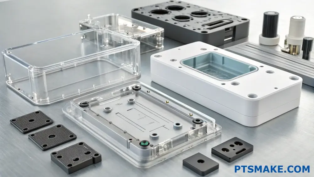
PC is extensively used in electronic devices due to its electrical insulation properties and durability. At PTSMAKE, we frequently manufacture PC components for:
- Smartphone cases
- Laptop housings
- Display screens
- Electronic enclosures
Automotive Industry
The automotive sector values PC for its impact resistance and thermal stability:
- Headlight lenses
- Interior components
- Instrumental panels
- Safety shields
Medical Devices
PC’s biocompatibility makes it perfect for medical applications:
- Surgical instruments
- Medical device housings
- Laboratory equipment
- Sterilizable containers
Manufacturing Considerations
Processing Methods
PC can be processed through various manufacturing methods:
| Method | Advantages | Common Applications |
|---|---|---|
| Injection Molding | High volume, complex shapes | Electronic housings |
| CNC Machining | Precision, low volume | Prototypes, custom parts |
| Thermoforming | Large panels, cost-effective | Signage, displays |
Design Guidelines
When designing PC parts, consider these crucial factors:
- Wall thickness uniformity
- Proper draft angles
- Adequate radii on corners
- Stress concentration avoidance
Material Grades and Selection
Different grades of PC are available for specific applications:
Optical Grade
- Used for lenses and transparent components
- Features 90% light transmission
- Requires careful processing to maintain clarity
Flame Retardant Grade
- Meets UL94 V-0 standards
- Ideal for electrical applications
- Contains special additives for fire resistance
Medical Grade
- FDA approved
- Sterilization compatible
- Enhanced purity standards
Sustainability Aspects
PC offers several environmental benefits:
- Recyclable material
- Long service life
- Energy-efficient processing
- Reduced transportation weight
At PTSMAKE, we prioritize sustainable manufacturing practices and offer recycling solutions for PC components.
Cost Considerations
The total cost of PC parts depends on several factors:
| Factor | Impact on Cost |
|---|---|
| Material Grade | Medium to High |
| Production Volume | High |
| Processing Method | Medium |
| Part Complexity | High |
Technical Support and Quality Assurance
As a manufacturer, PTSMAKE provides comprehensive support:
- Material selection guidance
- Design optimization
- Quality control processes
- Production efficiency improvements
Through years of experience in polymer processing, I’ve learned that successful PC part manufacturing requires attention to detail and proper technical knowledge. We ensure each project meets specific requirements while maintaining cost-effectiveness.
What Is the Best Plastic for CNC Machining?
Choosing the right plastic for CNC machining can be overwhelming with dozens of materials available. Many engineers and designers struggle to balance material properties, machinability, and cost-effectiveness, often leading to costly mistakes or suboptimal performance.
The best plastic for CNC machining depends on your specific application requirements. Generally, Polycarbonate (PC) stands out for its excellent combination of mechanical strength, dimensional stability, and machinability, making it ideal for many precision engineering applications.
Understanding Material Properties for CNC Machining
When selecting plastics for CNC machining, we need to consider several key properties. At PTSMAKE, I’ve found that understanding these fundamental characteristics helps make informed decisions:
Mechanical Properties
- Tensile Strength
- Impact Resistance
- Flexural Modulus
- Wear Resistance
These properties determine how the material will perform under various conditions. For example, a material with high impact resistance would be suitable for protective covers or housings.
Top Plastic Materials for CNC Machining
Let’s examine the most commonly used plastics in CNC machining and their typical applications:
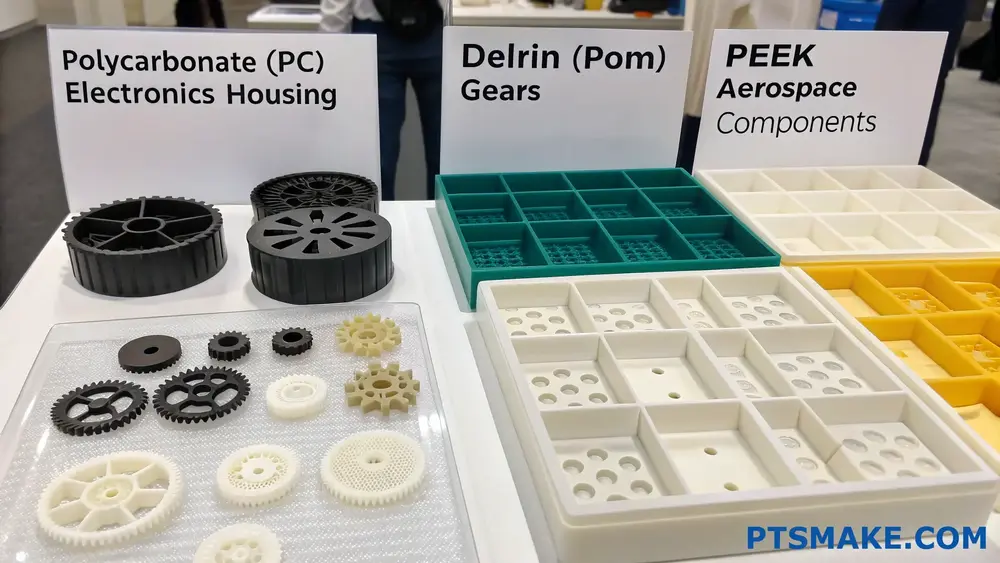
| Material | Key Advantages | Common Applications | Cost Level |
|---|---|---|---|
| Polycarbonate (PC) | High impact strength, optical clarity | Electronics housing, medical devices | Medium-High |
| Delrin (POM) | Low friction, dimensional stability | Gears, bearings, bushings | Medium |
| PEEK | High temperature resistance, chemical resistance | Aerospace components, medical implants | High |
| ABS | Cost-effective, good machinability | Prototypes, consumer products | Low |
| Nylon | Wear resistance, self-lubricating | Moving parts, mechanical components | Medium |
Critical Factors in Material Selection
Temperature Resistance
The [glass transition temperature]2 of the material plays a crucial role in determining its performance under various operating conditions. At PTSMAKE, we carefully consider this factor when recommending materials to our clients.
Chemical Compatibility
Different plastics react differently to chemicals. Consider these aspects:
- Resistance to oils and greases
- Compatibility with cleaning agents
- Exposure to UV radiation
- Resistance to environmental factors
Cost Considerations
The total cost involves more than just material prices:
- Raw material cost
- Machining time and complexity
- Tool wear and replacement
- Production volume requirements
Machinability Factors
From my experience at PTSMAKE, successful CNC machining of plastics requires attention to:
- Cutting speed optimization
- Tool selection and geometry
- Cooling requirements
- Chip formation and evacuation
Industry-Specific Requirements
Different industries have unique requirements for plastic materials:
Medical Industry
- Biocompatibility
- Sterilization capability
- FDA compliance
- Traceability requirements
Aerospace Applications
- Fire retardancy
- Low smoke emission
- High strength-to-weight ratio
- Temperature stability
Automotive Sector
- Impact resistance
- Weather resistance
- Chemical compatibility
- Cost-effectiveness
Material Selection Guidelines
To help you make the right choice, consider these steps:
Define Application Requirements
- Operating temperature range
- Load conditions
- Environmental exposure
- Regulatory requirements
Evaluate Material Properties
- Mechanical specifications
- Chemical resistance
- Thermal characteristics
- Cost constraints
Consider Manufacturing Constraints
- Minimum wall thickness
- Maximum part size
- Surface finish requirements
- Tolerance specifications
At PTSMAKE, we’ve developed a comprehensive material selection process that helps our clients make informed decisions. We consider not only the technical requirements but also practical aspects like cost-effectiveness and production efficiency.
Optimizing Material Performance
To achieve optimal results in CNC machining of plastics:
Design Optimization
- Incorporate appropriate wall thicknesses
- Design for proper tool access
- Include stress-relief features
- Consider thermal expansion
Processing Parameters
- Use appropriate cutting speeds
- Maintain optimal feed rates
- Implement proper cooling strategies
- Select suitable tooling
Quality Control Measures
- Dimensional verification
- Material certification
- Surface finish inspection
- Functional testing
In our facility at PTSMAKE, we maintain strict quality control protocols to ensure consistent material performance across all projects.
What Are the Manufacturing Methods of Polycarbonate(PC)?
Manufacturing polycarbonate parts can be challenging due to the material’s unique properties. Many engineers struggle with choosing the right manufacturing method, leading to quality issues, increased costs, and production delays.
There are three main manufacturing methods for polycarbonate: injection molding, extrusion, and CNC machining. Each method has its specific applications and advantages, making the choice crucial for successful production outcomes.
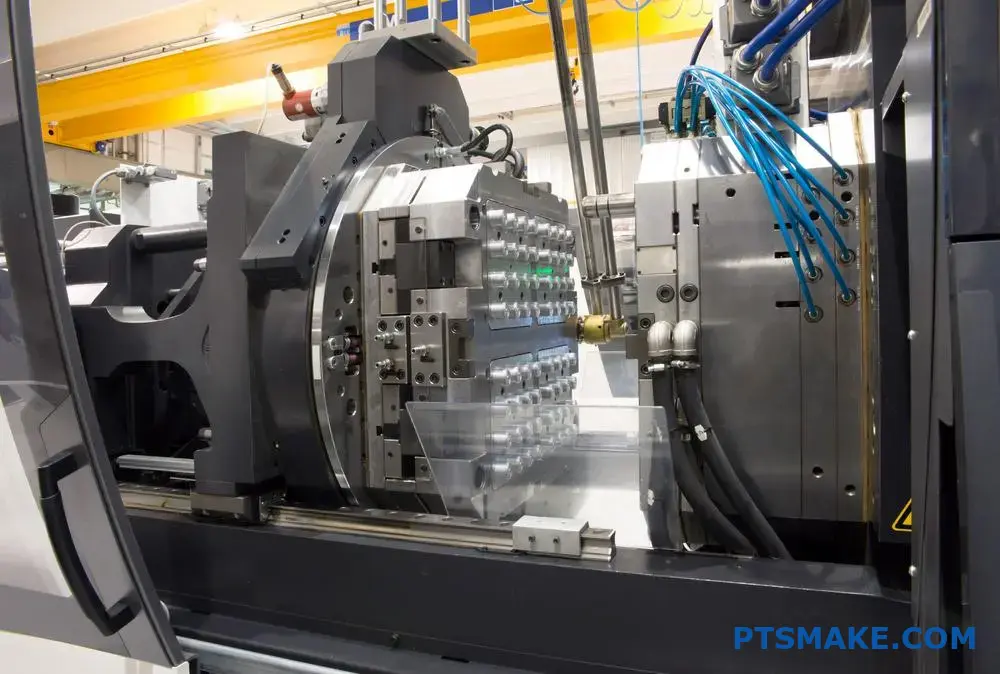
Injection Molding: The Most Versatile Method
Process Overview
Injection molding is a highly efficient manufacturing process for polycarbonate parts. The process involves melting PC pellets at temperatures between 280°C to 320°C and injecting the molten material into a mold cavity under high pressure. The [rheological behavior]3 of PC during this process requires precise control of processing parameters.
Key Advantages
- High production efficiency
- Excellent surface finish
- Complex geometry capability
- Cost-effective for large volumes
- Consistent part quality
Critical Processing Parameters
| Parameter | Recommended Range | Impact on Quality |
|---|---|---|
| Melt Temperature | 280-320°C | Affects flow and crystallinity |
| Mold Temperature | 80-120°C | Influences surface quality |
| Injection Pressure | 70-120 MPa | Determines filling pattern |
| Cooling Time | 3-8 seconds | Affects dimensional stability |
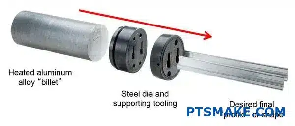
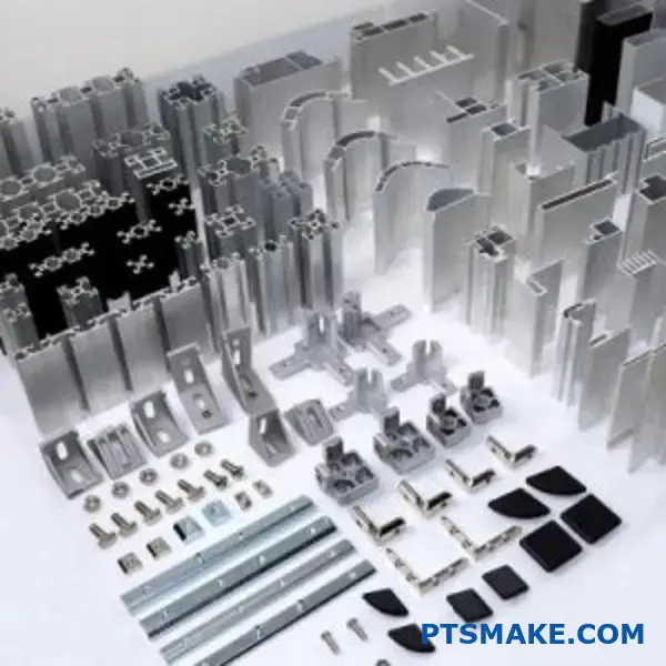
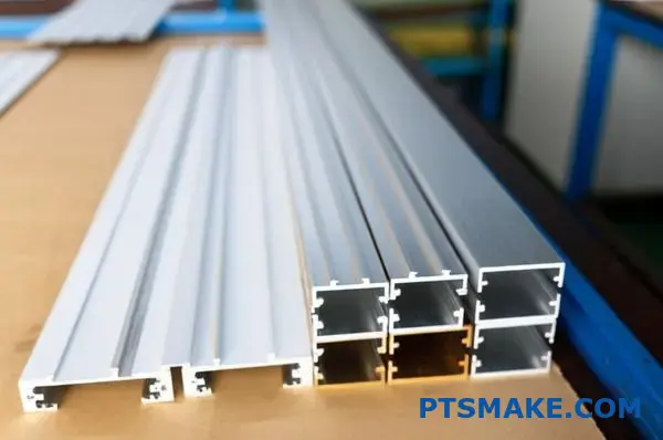
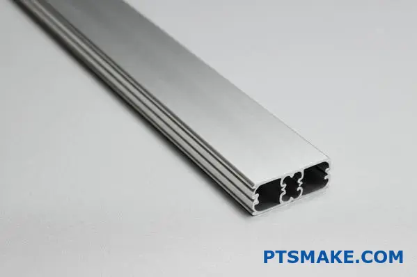
Extrusion: Ideal for Continuous Profiles
Process Characteristics
Extrusion is particularly suitable for producing continuous PC profiles such as sheets, tubes, and rods. At PTSMAKE, we’ve optimized our extrusion lines to maintain consistent material properties throughout the process.
Applications
- PC sheets for glazing
- Optical light guides
- Protection tubes
- Cable insulation
Temperature Control Requirements
| Zone | Temperature Range | Purpose |
|---|---|---|
| Feed Zone | 230-250°C | Material softening |
| Compression Zone | 260-280°C | Melting and mixing |
| Metering Zone | 270-290°C | Homogenization |
| Die Zone | 280-300°C | Final shaping |
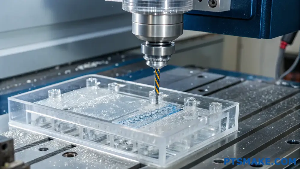
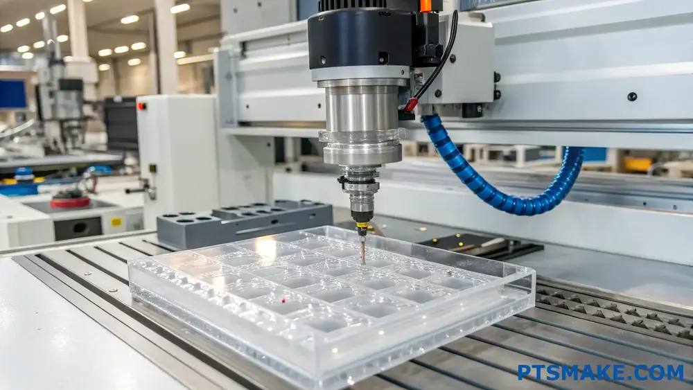
CNC Machining: Precision for Complex Parts
Process Benefits
CNC machining offers unmatched precision for PC parts. With our advanced 5-axis CNC machines, we can achieve tolerances as tight as ±0.025mm. This method is particularly valuable for prototypes and low-volume production runs.
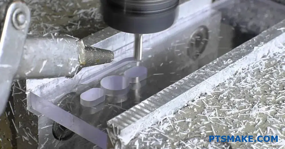
Machining Considerations
- Use sharp, polished cutting tools
- Maintain moderate cutting speeds
- Apply proper cooling techniques
- Consider stress relief before final machining
Recommended Cutting Parameters
| Operation | Speed (m/min) | Feed Rate (mm/rev) | Depth of Cut (mm) |
|---|---|---|---|
| Roughing | 150-200 | 0.2-0.3 | 2-4 |
| Finishing | 200-250 | 0.1-0.2 | 0.5-1 |
| Drilling | 100-150 | 0.1-0.15 | – |
Material Preparation and Handling
Drying Requirements
Proper drying is crucial for all PC manufacturing methods. I always emphasize to our clients that PC must be dried at 120°C for 4-6 hours before processing to prevent quality issues.
Storage Guidelines
- Keep in sealed containers
- Maintain relative humidity below 50%
- Store at room temperature
- Avoid direct sunlight exposure
Quality Control Measures
Testing Methods
- Dimensional inspection
- Impact resistance testing
- Optical clarity assessment
- Stress pattern analysis
To ensure consistent quality, we implement rigorous testing protocols at every stage of production. Our quality control system has earned us ISO 9001:2015 certification and trust from leading companies in various industries.
Environmental Considerations
Sustainability Practices
At PTSMAKE, we’ve implemented several sustainable practices in our PC manufacturing processes:
- Closed-loop cooling systems
- Material recycling programs
- Energy-efficient equipment
- Waste reduction initiatives
Our commitment to environmental responsibility has not only reduced our carbon footprint but also helped our clients meet their sustainability goals.
Through careful selection of manufacturing methods and strict adherence to processing parameters, we consistently achieve high-quality PC parts that meet or exceed customer specifications. The key is understanding each method’s strengths and limitations, then choosing the most appropriate one based on specific project requirements.
What Are the Advantages and Disadvantages of Polycarbonate(PC) Machining?
Are you struggling to decide whether PC machining is the right choice for your project? Many engineers and product designers find themselves overwhelmed when weighing the pros and cons of PC machining, especially when precision and durability requirements are critical.
Polycarbonate (PC) machining offers unique advantages like excellent impact resistance and optical clarity, but also presents challenges such as thermal sensitivity and tool wear. Understanding these factors is crucial for making informed manufacturing decisions.
Advantages of PC Machining
Superior Impact Resistance
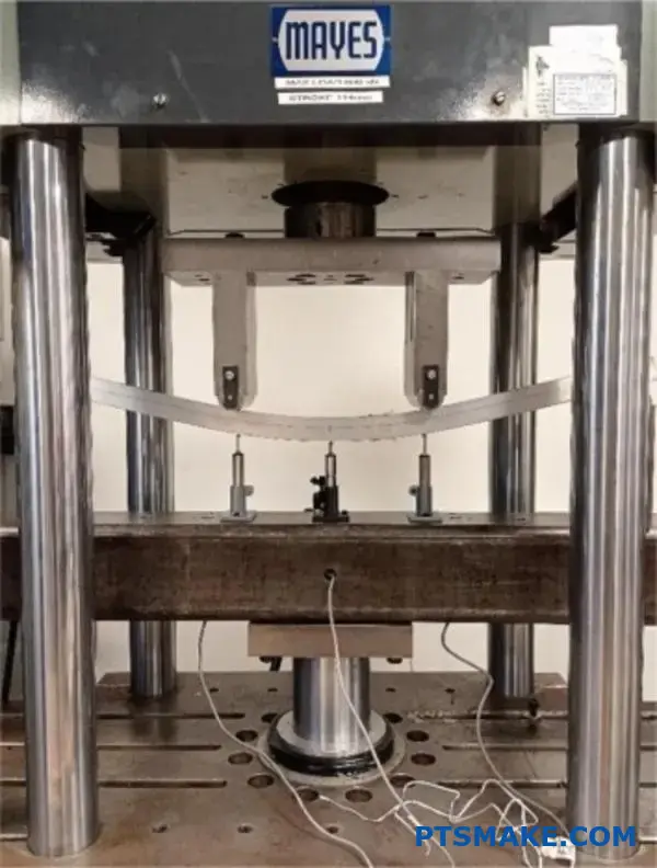
PC’s exceptional impact resistance makes it ideal for demanding applications. The material’s molecular structure4 provides outstanding durability, making it 250 times stronger than glass. At PTSMAKE, we regularly machine PC parts for protective equipment and high-stress applications.
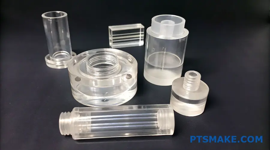
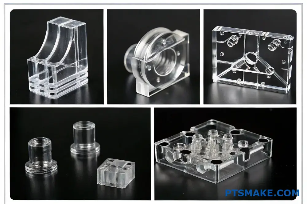
Optical Clarity
One of PC’s most valuable properties is its outstanding optical transparency, reaching up to 89% light transmission. This makes it perfect for:
- Transparent prototypes
- Optical components
- Display windows
- Protective covers
Dimensional Stability
PC maintains its shape and dimensions across a wide temperature range (-40°C to 120°C). This stability ensures:
- Consistent part performance
- Reliable assembly fit
- Reduced warpage issues
Disadvantages of PC Machining
Heat Sensitivity During Machining
Temperature control is critical when machining PC. The material can:
- Soften at relatively low temperatures
- Develop stress marks if overheated
- Require specific cutting parameters
To address these challenges, we use specialized cooling techniques and optimized cutting speeds at our facility.
Tool Wear Considerations
PC can be abrasive on cutting tools, leading to:
| Issue | Impact | Solution |
|---|---|---|
| Rapid tool wear | Increased costs | Regular tool replacement |
| Surface finish degradation | Quality issues | Optimized cutting parameters |
| Edge quality problems | Dimensional accuracy | Specialized tooling |
Cost Implications
PC machining can be more expensive than other plastics due to:
- Higher material costs
- Specialized tooling requirements
- Longer machining times
- Cooling system needs
Advanced Considerations
Surface Treatment Options
Post-machining treatments can enhance PC parts:
- Flame polishing for optical clarity
- Anti-scratch coatings
- UV protection layers
- Chemical resistance treatments
Material Grade Selection
Choosing the right PC grade is crucial:
| Grade Type | Best For | Key Features |
|---|---|---|
| Optical Grade | Lenses, displays | Highest clarity |
| Medical Grade | Healthcare devices | FDA compliant |
| Industrial Grade | Structural parts | Enhanced durability |
| UV-Stabilized | Outdoor applications | Weather resistance |
Design Optimization for PC Machining
To achieve the best results, consider these design aspects:
Wall Thickness
- Minimum: 1.5mm for structural stability
- Maximum: 12mm to prevent internal stress
- Optimal: 3-6mm for most applications
Corner Radii
- Internal: Minimum 1mm
- External: Minimum 0.5mm
- Larger radii improve strength
Feature Spacing
- Minimum 0.8mm between features
- Allow for tool access
- Consider fixturing requirements
Quality Control Measures
At PTSMAKE, we implement rigorous quality control:
- Dimensional inspection using CMM
- Optical clarity testing
- Impact resistance verification
- Stress pattern analysis
Application-Specific Considerations
Different industries require specific approaches:
Medical Industry
- Biocompatibility testing
- Sterilization compatibility
- Documentation requirements
Automotive Sector
- Impact resistance testing
- Temperature cycling
- UV stability verification
Electronics Industry
- EMI shielding options
- Static discharge prevention
- Assembly verification
Best Practices for PC Machining
To ensure optimal results:
Tool Selection
- Use sharp, polished cutting tools
- Maintain proper tool geometry
- Regular tool inspection
Cutting Parameters
- Lower speeds than metal
- Consistent feed rates
- Appropriate depth of cut
Cooling Strategy
- Use compatible coolants
- Maintain steady temperature
- Avoid thermal shock
Through careful consideration of these factors, we can maximize the benefits of PC machining while minimizing its drawbacks. The key is understanding your specific application requirements and implementing appropriate manufacturing strategies.
What Are the Key Parameters for Successful Polycarbonate (PC) CNC Machining?
Many manufacturers struggle with Polycarbonate CNC machining, often encountering issues like melting, chipping, and poor surface finish. These challenges can lead to costly material waste, production delays, and rejected parts that don’t meet specifications.
Successful PC CNC machining requires careful control of cutting parameters, including spindle speed (800-1000 RPM), feed rate (0.1-0.2 mm/rev), and cutting depth (0.2-0.5 mm). Proper cooling and tool selection are also essential for achieving optimal results.
Critical Cutting Parameters
Spindle Speed
The [thermal conductivity]5 of PC makes it particularly sensitive to heat generation during machining. I recommend maintaining spindle speeds between 800-1000 RPM for most applications. Higher speeds can cause material softening and deformation, while lower speeds might result in rough surfaces.
Feed Rate Control
Based on my experience working with various PC grades, optimal feed rates typically fall between 0.1-0.2 mm/revolution. Here’s a detailed breakdown:
| Material Thickness (mm) | Feed Rate (mm/rev) | Recommended Application |
|---|---|---|
| 1-3 | 0.10-0.15 | Precision components |
| 3-6 | 0.15-0.18 | General purpose |
| 6+ | 0.18-0.20 | Heavy-duty parts |
Tool Selection and Management
Cutting Tool Geometry
For PC machining, I’ve found that tools with the following specifications work best:
- Relief angle: 5-7 degrees
- Rake angle: 0-5 degrees
- Helix angle: 30-35 degrees
Tool Material Selection
Different tool materials offer varying advantages:
| Tool Material | Advantages | Best Used For |
|---|---|---|
| Carbide | Long tool life, excellent finish | High-volume production |
| HSS | Cost-effective, good for prototypes | Low-volume runs |
| Diamond-coated | Superior surface finish | Premium components |
Cooling Strategies
Coolant Selection
At PTSMAKE, we primarily use water-soluble coolants with specific characteristics:
- Concentration: 5-8%
- pH level: 7.5-8.5
- Flow rate: 2-3 L/min
Air Cooling Techniques
When liquid coolants aren’t suitable, compressed air cooling can be effective:
- Pressure: 6-8 bar
- Nozzle distance: 50-75mm
- Multiple nozzle positions for complex geometries
Surface Finish Optimization
Roughing Operations
For initial material removal:
- Depth of cut: 0.5-1.0mm
- Step-over: 40-50% of tool diameter
- Higher feed rates acceptable
Finishing Operations
To achieve superior surface quality:
- Depth of cut: 0.1-0.2mm
- Step-over: 10-15% of tool diameter
- Reduced feed rates
Quality Control Measures
Dimensional Accuracy
Maintaining tight tolerances requires:
- Regular tool wear monitoring
- Temperature-controlled environment (20-22°C)
- Proper workpiece fixturing
Common Quality Issues and Solutions
| Issue | Cause | Solution |
|---|---|---|
| Chipping | Excessive feed rate | Reduce feed rate by 20% |
| Melting | High spindle speed | Lower speed, increase cooling |
| Poor finish | Dull tools | Replace or resharpen tools |
Material Handling Considerations
Storage Requirements
Proper PC storage significantly impacts machining success:
- Temperature: 18-24°C
- Humidity: 40-60%
- Protected from UV exposure
Pre-machining Preparation
Steps I always recommend:
- Acclimate material for 24 hours
- Inspect for any existing damage
- Clean surface of contaminants
Cost Optimization
Material Utilization
Efficient material usage strategies:
- Nested part layouts
- Appropriate stock sizing
- Scrap material recovery
Production Efficiency
Ways to maximize throughput:
- Optimized tool paths
- Minimal tool changes
- Efficient workholding solutions
Through implementing these parameters at PTSMAKE, we’ve achieved consistent success in PC machining across various applications. The key is maintaining a balance between speed, accuracy, and surface quality while preventing thermal damage to the material.
How Does Polycarbonate (PC) Compare to Other Plastics in CNC Machining?
Many engineers and designers struggle to choose the right plastic material for their CNC machining projects. With numerous options available, selecting between polycarbonate and other plastics can be overwhelming, especially when considering factors like machinability, cost, and performance requirements.
Polycarbonate (PC) stands out in CNC machining due to its exceptional combination of strength, transparency, and heat resistance. Compared to other plastics, PC offers superior impact resistance and dimensional stability, making it ideal for demanding applications.
Material Properties Comparison
When comparing PC to other commonly machined plastics, several key properties need consideration. Through my experience at PTSMAKE, I’ve found that understanding these differences is crucial for successful project outcomes.
Mechanical Properties
The [crystallinity]6 of different plastics significantly affects their machining characteristics. Here’s how PC compares to other common engineering plastics:
| Property | PC | ABS | POM | PEEK |
|---|---|---|---|---|
| Tensile Strength (MPa) | 65-75 | 40-50 | 62-70 | 90-100 |
| Impact Strength (J/m) | 600-850 | 200-400 | 80-160 | 170-200 |
| Heat Deflection (°C) | 140 | 98 | 110 | 160 |
Machining Characteristics
In my daily operations at PTSMAKE, I’ve observed distinct differences in how various plastics respond to machining:
Cutting Speed and Feed Rates
PC requires specific machining parameters for optimal results:
- Lower cutting speeds compared to softer plastics
- Moderate feed rates to prevent melting
- Sharp cutting tools to minimize heat generation
Tool Wear and Surface Finish
Different plastics affect tooling differently:
| Material | Tool Wear Rate | Surface Finish Quality | Chip Formation |
|---|---|---|---|
| PC | Moderate | Excellent | Continuous |
| ABS | Low | Good | Discontinuous |
| PMMA | High | Excellent | Brittle |
| POM | Low | Very Good | Continuous |
Cost Considerations
The economic aspects of PC machining compared to other plastics include:
Material Costs
- PC: $8-12 per kg
- ABS: $4-6 per kg
- PMMA: $5-8 per kg
- POM: $6-9 per kg
Processing Costs
At PTSMAKE, we’ve optimized our processes to manage costs effectively:
Machine Time
- PC requires moderate cutting speeds
- Additional cooling time may be needed
- Setup time similar to other plastics
Tool Consumption
- Moderate tool wear rate
- Special tooling rarely required
- Regular maintenance schedules
Application-Specific Advantages
PC offers unique benefits in various applications:
Optical Applications
- Superior light transmission
- Excellent clarity
- UV resistance
- Impact resistance
Structural Components
- High strength-to-weight ratio
- Good dimensional stability
- Excellent heat resistance
- Superior impact resistance
Environmental Considerations
Modern manufacturing must consider environmental impact:
Recyclability
- PC is 100% recyclable
- Can be reprocessed multiple times
- Lower energy consumption compared to virgin material
Sustainability Practices
At PTSMAKE, we implement:
- Efficient material usage
- Waste reduction programs
- Recycling initiatives
Industry-Specific Performance
Different industries require specific material properties:
Aerospace
- High strength requirements
- Temperature resistance
- Lightweight solutions
- Precise tolerances
Medical
- Biocompatibility
- Sterilization capability
- Chemical resistance
- Dimensional stability
Consumer Electronics
- Impact resistance
- Aesthetic appeal
- Dimensional stability
- Heat resistance
Practical Recommendations
Based on my experience, here are key considerations:
When to Choose PC
- High impact resistance required
- Optical clarity needed
- Operating temperatures above 100°C
- Outdoor applications
When to Consider Alternatives
- Cost-sensitive projects
- Low mechanical stress applications
- Chemical exposure environments
- High precision tolerance requirements
Through our work at PTSMAKE, we’ve successfully machined thousands of PC components for various industries. The material’s versatility and performance characteristics make it an excellent choice for many applications, though careful consideration of specific project requirements remains essential.
What Surface Finishes Are Achievable With Polycarbonate (PC) CNC Machining?
Getting the perfect surface finish on Polycarbonate CNC machined parts can be challenging. Many manufacturers struggle with achieving consistent surface quality, especially when dealing with this transparent and scratch-sensitive material. The wrong approach can lead to visible tool marks, clouding, or uneven textures.
Polycarbonate CNC machining can achieve various surface finishes ranging from rough (Ra 3.2) to mirror-like (Ra 0.2). The specific finish depends on machining parameters, tooling selection, and post-processing techniques applied to the PC parts.
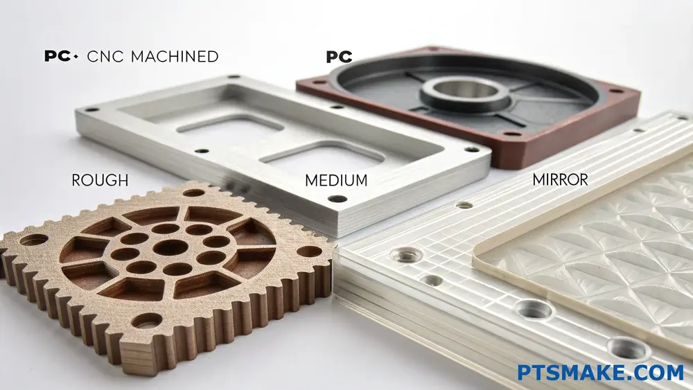
Understanding Surface Roughness Measurements
Surface roughness is measured using the [arithmetical mean roughness]7 value (Ra), which quantifies the microscopic surface variations. For PC CNC machining, we commonly work with Ra values between 0.2 and 3.2 micrometers. At PTSMAKE, we’ve developed specific machining protocols for each level of surface finish.
Standard Surface Finish Options
Here are the most common surface finishes we can achieve with PC CNC machining:
| Finish Type | Ra Value (μm) | Typical Applications | Visual Appearance |
|---|---|---|---|
| Rough | 3.2 | Industrial components | Matte, visible tool marks |
| Medium | 1.6 | General purpose parts | Semi-smooth, slight marks |
| Fine | 0.8 | Consumer products | Smooth, minimal marks |
| Ultra-fine | 0.4 | Optical components | Very smooth, no visible marks |
| Mirror | 0.2 | Display parts | High gloss, reflective |
Machining Parameters for Different Finishes
Cutting Speed and Feed Rate
The relationship between cutting parameters and surface finish is crucial:
- High cutting speeds (500-1000 m/min) with low feed rates produce smoother finishes
- Lower speeds (200-400 m/min) are better for rough cuts
- Feed rates typically range from 0.1 to 0.5 mm/rev depending on the desired finish
Tool Selection
Tool choice significantly impacts surface quality:
- Diamond-coated tools provide the finest finishes
- Carbide tools work well for medium finishes
- HSS tools are suitable for rough cuts
Post-Processing Techniques
Mechanical Polishing
Mechanical polishing can enhance surface finish:
- Progressive grit sandpaper (220-2000 grit)
- Buffing compounds
- Polishing wheels
Chemical Treatment
Some chemical treatments can improve surface appearance:
- Vapor polishing
- Chemical smoothing
- Anti-scratch coatings
Environmental Considerations
Temperature control during machining is critical:
- Optimal machining temperature: 20-25°C
- Proper cooling helps prevent:
- Material deformation
- Surface defects
- Tool wear
Industry-Specific Requirements
Different industries require various surface finishes:
Medical Industry
- Ultra-smooth finishes (Ra 0.2-0.4)
- Biocompatible surface treatment
- Sterilization-compatible finishes
Automotive Applications
- Medium finish (Ra 0.8-1.6)
- Weather-resistant coatings
- UV-stable surface treatments
Consumer Electronics
- High-gloss finishes (Ra 0.2-0.4)
- Scratch-resistant coatings
- Aesthetic consistency
Quality Control Measures
To ensure consistent surface finish:
- Regular tool wear monitoring
- Surface roughness testing
- Visual inspection
- Dimensional verification
Common Challenges and Solutions
Surface Defects
Common issues and their solutions:
| Defect Type | Cause | Solution |
|---|---|---|
| Chatter marks | Tool vibration | Adjust speed/feed rates |
| Burn marks | Excessive heat | Improve cooling |
| Tool marks | Worn tools | Replace/sharpen tools |
| Clouding | Chemical reaction | Adjust coolant mixture |
Material-Specific Considerations
PC requires special attention:
- Proper tool clearance angles
- Appropriate cutting fluid selection
- Temperature monitoring
- Stress relief procedures
Cost Implications
Surface finish quality affects cost:
- Basic finish: Standard pricing
- Medium finish: 20-30% cost increase
- Mirror finish: 50-100% cost increase
Recent Developments
New technologies improving surface finish:
- Advanced CNC controls
- Improved cutting tools
- Better cooling systems
- Automated polishing systems
At PTSMAKE, we continually invest in these technologies to provide better surface finishes for our clients’ PC parts. Our experience shows that achieving the right surface finish is a balance of proper machining parameters, tool selection, and post-processing techniques.
I recommend starting with a clear understanding of your application requirements and working backwards to determine the most cost-effective surface finish that meets your needs. This approach has helped many of our clients optimize their PC part manufacturing processes while maintaining quality standards.
What Industries Commonly Use Polycarbonate (PC) CNC Machined Parts?
Finding the right material for precision parts can be challenging. Many engineers and product designers struggle to identify which industries benefit most from Polycarbonate CNC machined components, leading to missed opportunities and suboptimal material choices.
Polycarbonate (PC) CNC machined parts are widely used in aerospace, medical, automotive, electronics, and consumer goods industries due to their exceptional strength, optical clarity, and thermal resistance. These industries rely on PC parts for critical applications requiring both durability and precision.
Aerospace Industry Applications
The aerospace industry demands materials that can withstand extreme conditions while maintaining structural integrity. I’ve observed that PC CNC machined parts excel in this sector for several reasons:
Aircraft Interior Components
- Cabin window components
- Instrument panel covers
- Lighting fixtures
- Storage compartment parts
The [thermoplastic properties]8 of PC make it ideal for these applications, as it maintains stability across wide temperature ranges typically encountered during flights.
Medical Device Manufacturing
In the medical field, PC CNC machined parts have become increasingly important:
Critical Medical Equipment
- Surgical instrument handles
- Diagnostic device housings
- Medical imaging equipment components
- Laboratory equipment parts
These applications require materials that can withstand sterilization processes while maintaining dimensional stability.
Automotive Industry Implementation
The automotive sector leverages PC CNC machined parts for:
Vehicle Components
- Headlight assemblies
- Interior trim pieces
- Sensor housings
- Dashboard components
| Application | Key Benefits | Common Uses |
|---|---|---|
| Exterior Parts | UV resistance, Impact strength | Lighting covers, Mirror housings |
| Interior Components | Heat resistance, Durability | Dashboard elements, Control panels |
| Under-hood Parts | Chemical resistance, Temperature stability | Sensor housings, Fluid containers |
Electronics Industry Applications
The electronics industry particularly benefits from PC CNC machined parts:
Electronic Device Components
- Protective housings
- Display covers
- Component carriers
- Connector bodies
At PTSMAKE, we regularly produce these components with tight tolerances and complex geometries.
Consumer Goods Manufacturing
Consumer products frequently incorporate PC CNC machined parts:
Common Applications
- High-end appliance components
- Sports equipment parts
- Safety equipment
- Optical devices
| Product Category | PC Properties Utilized | Example Applications |
|---|---|---|
| Safety Equipment | Impact resistance, Clarity | Safety glasses, Face shields |
| Sporting Goods | Durability, Lightweight | Protective gear, Equipment housings |
| Home Appliances | Heat resistance, Strength | Control panels, Display covers |
Industrial Equipment Sector
The industrial sector relies heavily on PC CNC machined parts:
Industrial Applications
- Machine guards
- Control panel covers
- Inspection windows
- Safety barriers
These components must withstand harsh industrial environments while maintaining visibility and strength.
Scientific Research Equipment
Research facilities often require specialized PC CNC machined parts:
Laboratory Equipment
- Test chamber windows
- Analytical instrument housings
- Observation ports
- Sample containers
I’ve seen an increasing demand for these components as research facilities upgrade their equipment.
Robotics and Automation
The robotics industry frequently uses PC CNC machined parts for:
Robotic Components
- Protective covers
- Sensor housings
- Visual system components
- Control interface panels
| Component Type | Critical Properties | Application Examples |
|---|---|---|
| Covers | Impact resistance, Transparency | Robot arm covers, Display shields |
| Housings | Dimensional stability, Durability | Sensor enclosures, Control boxes |
| Interface Components | Clarity, Weather resistance | HMI panels, Visualization windows |
Energy Sector Applications
The energy sector utilizes PC CNC machined parts in various ways:
Energy Applications
- Solar panel components
- Wind turbine parts
- Control system housings
- Inspection windows
These applications require materials that can withstand outdoor exposure while maintaining optical clarity and structural integrity.
At PTSMAKE, we understand these diverse industry requirements and provide precision PC CNC machined parts that meet specific industry standards. Our advanced manufacturing capabilities ensure that each component meets the exact specifications required for its intended application, whether it’s for aerospace, medical, or any other demanding industry.
How to Minimize Costs in Polycarbonate (PC) CNC Machining Projects?
In the competitive world of CNC machining, managing costs for Polycarbonate projects can be a significant challenge. Many manufacturers struggle with balancing quality requirements and budget constraints, often facing unnecessary expenses due to improper planning and material waste.
To minimize costs in Polycarbonate CNC machining projects, focus on optimizing design features, selecting appropriate tooling, and implementing efficient machining strategies. These approaches can reduce material waste, decrease machining time, and lower overall production expenses while maintaining quality standards.
Design Optimization Strategies
Simplify Part Geometry
One of the most effective ways to reduce costs is through thoughtful design optimization. I’ve found that complex geometries often lead to longer machining times and increased tool wear. By incorporating these design considerations:
- Avoid unnecessarily deep pockets
- Use standard corner radii
- Maintain uniform wall thickness
- Eliminate undercuts when possible
The [Design for Manufacturability]9 approach can significantly reduce machining time and complexity.
Material Selection and Usage
Proper material selection plays a crucial role in cost reduction:
| Material Grade | Cost Level | Recommended Applications |
|---|---|---|
| Standard PC | Low | General purpose parts |
| Optical Grade PC | Medium | Transparent components |
| UV-Stabilized PC | High | Outdoor applications |
Tooling Optimization
Tool Selection
Choosing the right cutting tools is essential for cost-effective PC machining:
- High-Speed Steel (HSS) tools for simple operations
- Carbide tools for complex features
- Diamond-coated tools for high-volume production
Cutting Parameters
| Parameter | Recommended Range | Impact on Cost |
|---|---|---|
| Cutting Speed | 300-500 m/min | Moderate |
| Feed Rate | 0.1-0.3 mm/rev | High |
| Depth of Cut | 0.5-2.0 mm | Significant |
Production Process Optimization
Batch Processing
At PTSMAKE, we’ve implemented several strategies to optimize batch processing:
- Group similar parts together
- Utilize multi-fixture setups
- Optimize tool paths for multiple parts
- Schedule similar operations consecutively
Quality Control Integration
Implementing quality control measures early can prevent costly mistakes:
- In-process inspection
- First article inspection
- Regular tool wear monitoring
- Temperature control during machining
Machine Operation Efficiency
Setup Time Reduction
To minimize setup time and associated costs:
- Use standardized workholding systems
- Prepare tools and fixtures offline
- Implement quick-change tooling
- Maintain organized workspace
Programming Optimization
Efficient CNC programming can significantly reduce costs:
- Optimize cutting paths
- Minimize tool changes
- Use appropriate feeds and speeds
- Include proper cooling strategies
Material Handling and Storage
Inventory Management
Proper inventory management helps reduce waste and carrying costs:
- Just-in-time ordering
- Proper storage conditions
- Material tracking systems
- Stock optimization
Scrap Reduction
Implementing effective scrap reduction strategies:
- Nesting parts efficiently
- Reusing larger scrap pieces
- Maintaining proper material storage
- Regular machine maintenance
Cost Monitoring and Control
Project Tracking
Implementing robust tracking systems:
| Cost Factor | Tracking Method | Review Frequency |
|---|---|---|
| Material Usage | Digital inventory | Weekly |
| Machine Time | Automated logging | Daily |
| Tool Wear | Visual inspection | Per batch |
| Quality Issues | Defect tracking | Real-time |
Continuous Improvement
Regular evaluation and improvement of processes:
- Regular process audits
- Employee training programs
- Technology updates
- Feedback implementation
Supplier Relationships
At PTSMAKE, we maintain strong relationships with suppliers to ensure cost-effective solutions:
- Volume pricing agreements
- Quality assurance programs
- Just-in-time delivery
- Technical support services
Environmental Considerations
Implementing environmentally conscious practices can lead to cost savings:
- Coolant recycling systems
- Energy-efficient equipment
- Waste reduction programs
- Sustainable material handling
These comprehensive strategies, when properly implemented, can significantly reduce costs in PC CNC machining projects while maintaining high quality standards. By focusing on these areas, manufacturers can achieve better cost control and improved operational efficiency.
What Design Considerations Are Critical for Polycarbonate (PC) CNC Machining?
Designing parts for Polycarbonate CNC machining often leads to unexpected challenges. Many engineers and designers struggle with warping, tool marks, and dimensional inaccuracies, causing project delays and increased costs that could have been avoided with proper design considerations.
Success in Polycarbonate CNC machining requires careful attention to material properties, design features, and machining parameters. Key considerations include wall thickness, corner designs, hole specifications, and surface finish requirements to ensure optimal part quality and manufacturability.
Material Properties Impact on Design
Understanding PC’s unique characteristics is essential for successful machining. The material exhibits [viscoelastic behavior]10 during machining, which affects how we approach design features. At PTSMAKE, we’ve developed specific guidelines based on PC’s properties:
Thermal Considerations
- Heat deflection temperature: 270°F (132°C)
- Thermal expansion coefficient: 70.2 × 10^-6 in/in/°F
- Cooling requirements during machining
Mechanical Properties
- Tensile strength: 9,500 psi
- Flexural modulus: 345,000 psi
- Impact resistance: 12-16 ft-lb/in
Wall Thickness and Structural Integrity
The proper wall thickness is crucial for maintaining structural integrity while preventing warping. Here’s a detailed breakdown:
| Feature Type | Minimum Thickness | Recommended Thickness | Maximum Thickness |
|---|---|---|---|
| Vertical Walls | 0.040" (1mm) | 0.080" (2mm) | 0.500" (12.7mm) |
| Supporting Ribs | 0.060" (1.5mm) | 0.100" (2.5mm) | 0.250" (6.35mm) |
| Base Sections | 0.080" (2mm) | 0.120" (3mm) | 0.750" (19mm) |
Corner and Edge Design Specifications
Proper corner design prevents stress concentration and ensures machinability:
External Corners
- Minimum radius: 0.020" (0.5mm)
- Optimal radius: 0.040" (1mm)
- Avoid sharp corners to prevent material stress
Internal Corners
- Minimum radius: 0.040" (1mm)
- Recommended radius: 0.080" (2mm)
- Include relief features for tool access
Hole and Thread Specifications
When designing holes in PC parts, consider these guidelines:
Through Holes
- Minimum diameter: 0.020" (0.5mm)
- Maximum depth-to-diameter ratio: 4:1
- Optimal hole spacing: 2x diameter
Threaded Features
- Minimum thread size: M3 or #4-40
- Maximum thread depth: 2.5x diameter
- Use threaded inserts for high-stress applications
Surface Finish Requirements
Surface finish significantly impacts both aesthetics and functionality:
Achievable Finishes
| Finish Type | Ra Value (μin) | Application |
|---|---|---|
| Mirror | 4-8 | Optical components |
| Fine | 16-32 | Visible surfaces |
| Standard | 32-63 | Non-critical surfaces |
| Rough | 63-125 | Hidden surfaces |
Tolerance Considerations
Maintaining tight tolerances requires special attention:
Standard Tolerances
- General dimensions: ±0.005" (0.127mm)
- Critical features: ±0.002" (0.051mm)
- Hole locations: ±0.003" (0.076mm)
Temperature Effects
- Account for thermal expansion
- Consider operating environment
- Plan for material stabilization
Design for Manufacturability (DFM)
I always emphasize these key DFM principles to our clients at PTSMAKE:
Tool Access
- Plan for standard tool lengths
- Consider approach angles
- Allow proper clearance for tool paths
Workholding
- Design appropriate clamping areas
- Include datum surfaces
- Plan for multiple setups if needed
Quality Control Measures
To ensure consistent part quality:
Inspection Points
- Critical dimensions
- Surface finish requirements
- Geometric tolerances
Documentation
- Detailed technical drawings
- Specific callouts for critical features
- Clear finish requirements
Cost Optimization Strategies
Optimize designs for cost-effectiveness while maintaining quality:
Design Simplification
- Minimize complex features
- Reduce setup changes
- Standardize feature sizes
Material Utilization
- Optimize part orientation
- Minimize material waste
- Consider stock sizes
At PTSMAKE, we provide comprehensive design support to ensure your PC parts are optimized for both performance and manufacturability. Our engineering team works closely with clients to refine designs before production begins, saving time and resources while ensuring superior results.
Learn how polymerization affects material properties and enhances the performance of polycarbonate. ↩
Learn about its importance in selecting materials for optimal performance in varied conditions. ↩
Understanding this behavior helps optimize processing parameters for improved production efficiency. ↩
Learn about polycarbonate’s unique properties that make it ideal for various applications. ↩
Understanding thermal conductivity helps enhance machining efficiency and prevents material degradation. ↩
Learn about crystallinity’s impact on machining characteristics for optimized project outcomes. ↩
Learn about surface roughness measurement for improved machining quality. ↩
Learn about the versatility and benefits of thermoplastic properties in CNC machining applications. ↩
Learn how DFM can enhance production efficiency and reduce costs effectively. ↩
Understand how material properties impact machining for enhanced part quality. ↩