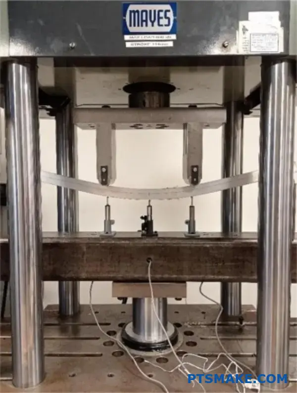
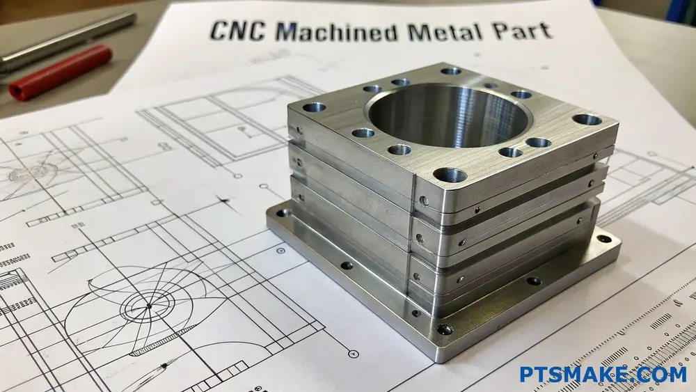
Getting DXF files ready for machining can be frustrating, especially when you discover errors during production. I’ve seen many clients waste time and money because their DXF files weren’t properly prepared, leading to costly revisions and production delays.
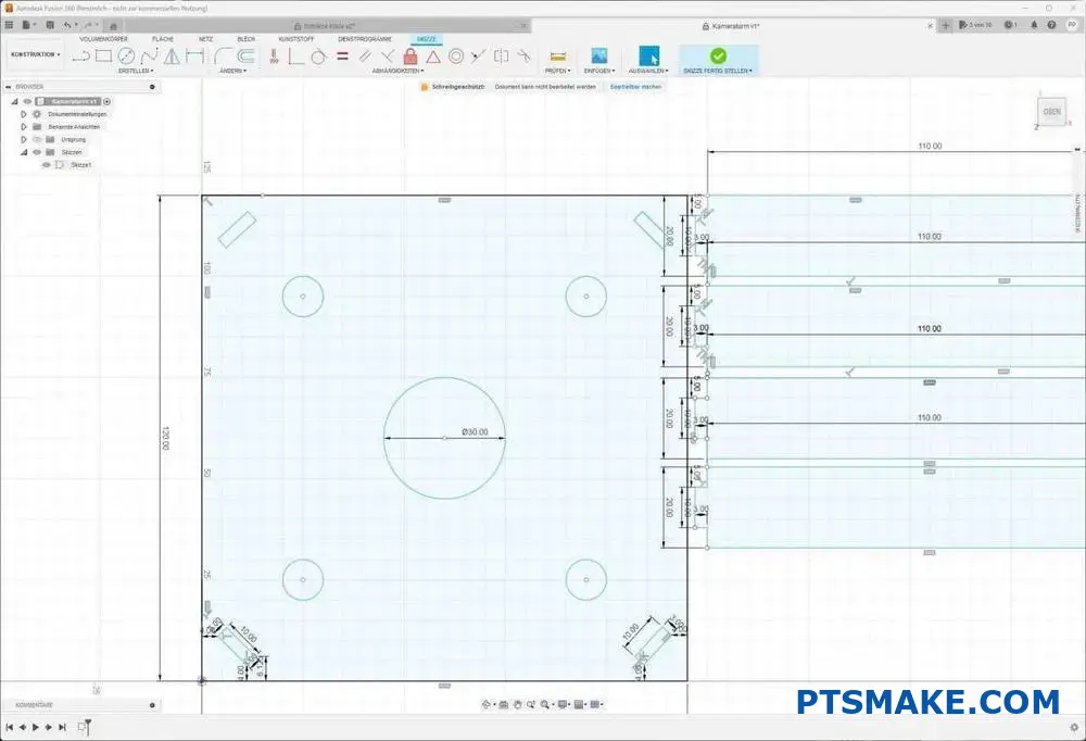
To prepare a DXF file for machining, you need to clean up unnecessary elements, check for overlapping lines, ensure proper scale, and verify all dimensions. Convert text to geometry, merge connecting lines, and save in a compatible DXF version.
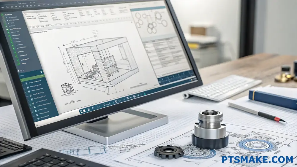
I know preparing DXF files can seem overwhelming, but getting it right is crucial for successful machining. Let me walk you through the essential steps and common mistakes to avoid based on my experience with thousands of customer files at PTSMAKE. The proper preparation will save you time, money, and headaches during production.
What Is The Best Program To Create A DXF File?
Have you ever found yourself staring at your screen, wondering which software to use for creating DXF files? The frustration of choosing between countless options, each claiming to be the best, can be overwhelming, especially when your project deadlines are looming.
The best program for creating DXF files is AutoCAD, offering unmatched precision and industry-standard compatibility. However, for cost-effective alternatives, Draftsight and LibreCAD provide excellent DXF file creation capabilities with user-friendly interfaces.
Understanding DXF File Format
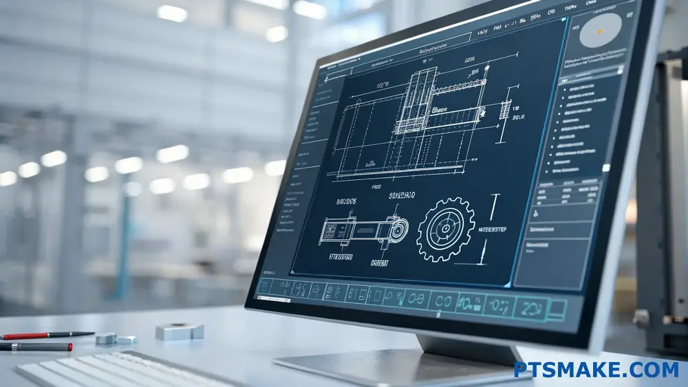
DXF (Drawing Exchange Format) files have become the backbone of modern CAD design and manufacturing. As someone deeply involved in precision manufacturing, I’ve witnessed how crucial proper DXF file creation is for successful production outcomes. The vector-based format1 ensures scalability without losing quality, making it ideal for manufacturing applications.
Key Features of DXF Files
- Universal compatibility across CAD platforms
- Preservation of precise measurements and dimensions
- Support for both 2D and 3D design elements
- Efficient data exchange between different software
Top Programs for Creating DXF Files
1. AutoCAD
AutoCAD remains the industry leader for creating DXF files. At PTSMAKE, we frequently receive AutoCAD-generated DXF files from clients, and they consistently provide excellent results for our CNC machining processes.
Key Benefits:
- Native DXF support
- Comprehensive drawing tools
- Industry-standard compatibility
- Regular updates and improvements
2. DraftSight
DraftSight offers a cost-effective alternative while maintaining professional-grade capabilities.
Key Features:
- AutoCAD-like interface
- Robust 2D design tools
- Excellent DXF export options
- Affordable pricing structure
3. LibreCAD
For those seeking a free option, LibreCAD stands out as a capable solution.
Advantages:
- Open-source platform
- Native DXF support
- Active community support
- Regular updates
Comparison of DXF Creation Software
| Software | Price Range | Learning Curve | Professional Features | File Compatibility |
|---|---|---|---|---|
| AutoCAD | $$$$ | High | Extensive | Excellent |
| DraftSight | $$ | Medium | Good | Very Good |
| LibreCAD | Free | Low | Basic | Good |
| FreeCAD | Free | Medium | Moderate | Good |
| QCAD | $ | Low | Basic | Good |
Industry-Specific Considerations
Manufacturing Requirements
In manufacturing, precision is paramount. When creating DXF files for CNC machining or other manufacturing processes, consider these factors:
- Dimensional accuracy
- Layer organization
- Entity types support
- Scale consistency
Design Workflow Integration
Your chosen software should seamlessly integrate with your existing design workflow. At PTSMAKE, we’ve optimized our processes to handle DXF files from various sources, ensuring smooth production regardless of the creation software.
Tips for Optimal DXF File Creation
Maintain Clean Geometry
- Remove unnecessary entities
- Check for overlapping lines
- Verify closed contours
Use Appropriate Scale
- Work in actual units
- Maintain consistent scale throughout
- Verify dimensions before export
Layer Management
- Organize entities logically
- Use meaningful layer names
- Separate different elements appropriately
Future Trends in DXF Creation
The landscape of DXF creation continues to evolve with emerging technologies:
- Cloud-based CAD solutions
- AI-assisted design tools
- Enhanced collaboration features
- Mobile compatibility
Cost Considerations
When selecting DXF creation software, consider these financial aspects:
Initial Investment
- Software purchase cost
- Training requirements
- Hardware requirements
Long-term Costs
- Subscription fees
- Upgrade costs
- Support services
Return on Investment
- Productivity gains
- Compatibility benefits
- Time savings
Best Practices for Manufacturing
Creating DXF files for manufacturing requires attention to detail:
File Preparation
- Double-check dimensions
- Verify units
- Clean up unnecessary elements
Quality Assurance
- Test file compatibility
- Verify export settings
- Validate geometry
Communication
- Include relevant metadata
- Document special requirements
- Maintain version control
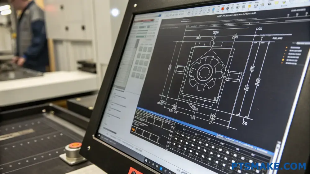
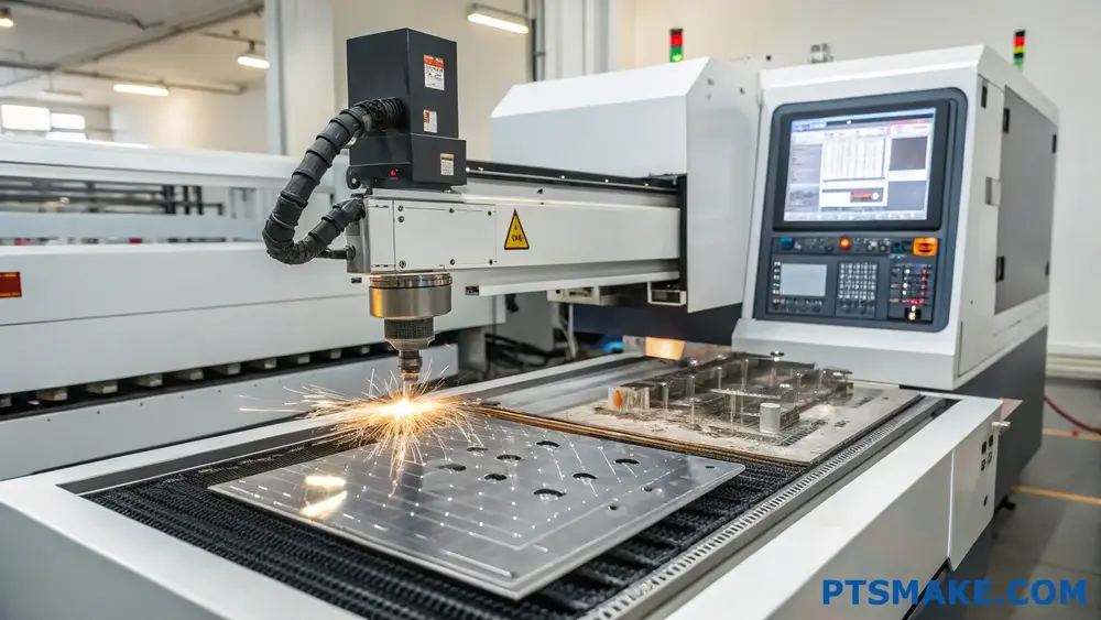
What Are Common Issues With DXF Files in CNC Manufacturing?
Have you ever sent a DXF file to a manufacturer only to hear it’s unusable? Or worse, received parts that don’t match your design specifications? These frustrating scenarios are more common than you might think, often leading to costly delays and wasted materials.
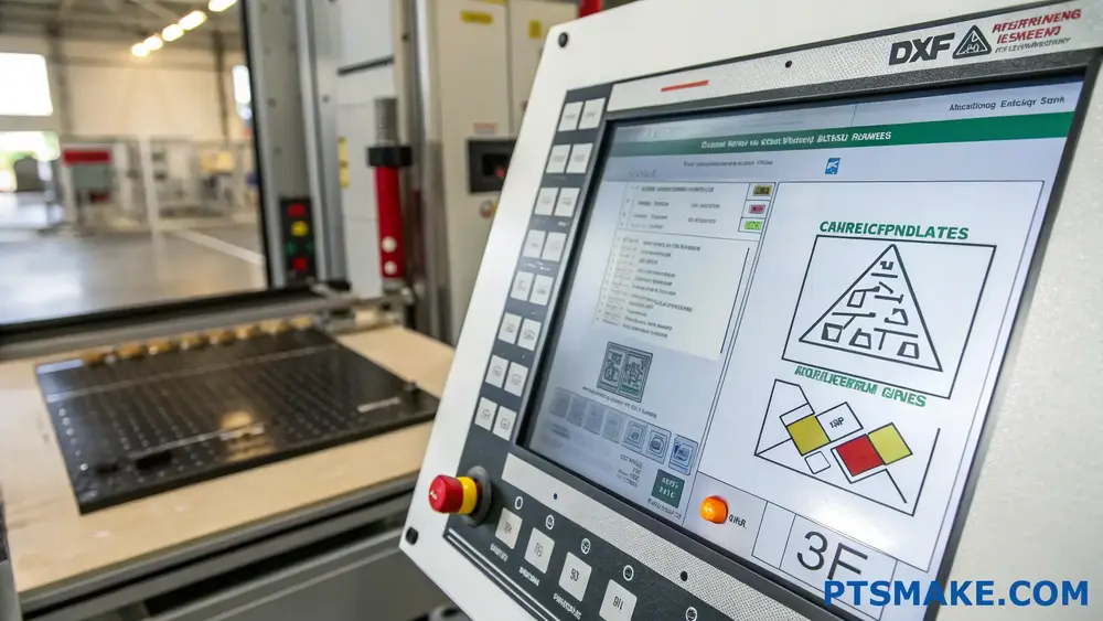
To ensure DXF file compatibility with CNC machines, focus on proper file creation, validation, and conversion. Key aspects include using supported DXF versions, cleaning up unnecessary entities, and maintaining proper scale and units. Regular testing with CAM software before production is essential.
Understanding DXF File Structure
Basic Components
DXF files contain several critical sections that determine their compatibility with CNC machines. The header section defines general file parameters, while the entities section contains actual geometric data. When working with polylines2 and other geometric elements, maintaining clean data structure is crucial.
Version Compatibility
Different CNC machines support various DXF versions. Here’s a compatibility overview:
| DXF Version | Common Usage | Compatibility Level |
|---|---|---|
| R12 | Legacy Systems | High |
| R14 | Standard Usage | Very High |
| 2000 | Modern Systems | Medium |
| 2004+ | Latest Features | Variable |
Essential File Preparation Steps
Clean Geometry
- Remove duplicate lines and points
- Connect fragmented lines
- Delete unused layers
- Merge overlapping entities
Scale and Units Configuration
- Always work in real-world units
- Verify scale factors before export
- Document unit settings for reference
Advanced Compatibility Techniques
Layer Management
Proper layer organization significantly impacts CNC compatibility. I recommend creating separate layers for:
- Cutting paths
- Reference geometry
- Dimensions
- Text annotations
Entity Types and Limitations
Common entity types that require special attention:
- Splines and curves
- Hatching patterns
- Custom line types
- Block references
Validation and Testing Procedures
Pre-Production Checks
Before sending files to production:
- Run geometry validation tools
- Check for closed contours
- Verify entity connections
- Test with CAM software
Common Error Resolution
I’ve developed a systematic approach to resolve frequent issues:
| Error Type | Common Cause | Resolution Method |
|---|---|---|
| Missing Lines | Import Settings | Adjust Import Parameters |
| Scale Issues | Unit Mismatch | Standardize Units |
| Corrupt Geometry | File Conversion | Rebuild Problem Areas |
| Layer Conflicts | Naming Conventions | Implement Standard Names |
File Optimization Strategies
Size Reduction
Optimizing file size improves processing:
- Remove unused definitions
- Purge redundant data
- Compress where possible
- Simplify complex geometry
Performance Enhancement
To improve CNC processing:
- Use simple line segments where possible
- Avoid unnecessary complexity
- Maintain consistent entity types
- Keep file structure organized
Integration with CAM Software
Software Compatibility
Different CAM packages handle DXF files differently. Key considerations include:
- Feature recognition capabilities
- Entity interpretation methods
- Processing algorithms
- Output options
Workflow Optimization
Establish a standardized workflow:
- Initial file review
- Geometry cleanup
- Entity validation
- Test processing
- Production preparation
At PTSMAKE, we’ve implemented these practices across our CNC manufacturing processes, significantly reducing file-related issues and improving production efficiency. Our engineering team regularly updates our compatibility protocols to accommodate new software versions and machine capabilities.
Quality Assurance Methods
Automated Checking
Implement automated checks for:
- Geometry integrity
- Layer consistency
- Scale accuracy
- Entity validity
Manual Verification
Critical manual checks include:
- Visual inspection of geometry
- Toolpath simulation
- Test cuts on sample material
- Final dimension verification
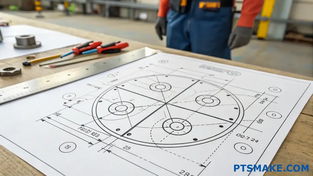
What Are Common DXF File Errors And How To Avoid Them?
Have you ever spent hours preparing a DXF file for CNC machining, only to discover errors that cause production delays and increased costs? The frustration of dealing with corrupted geometry, incompatible layers, or scaling issues can turn a simple project into a manufacturing nightmare.
DXF file errors commonly include missing lines, improper scaling, overlapping entities, and incorrect layer assignments. These issues can significantly impact manufacturing accuracy and efficiency. Understanding these common problems and implementing proper prevention methods ensures smooth CNC machining operations.

Understanding Layer Management Issues
Layer management is crucial for successful DXF file handling. Poor layer organization often leads to manufacturing confusion and errors. At PTSMAKE, we recommend implementing a standardized layer naming convention and structure. This helps maintain consistency across different CAD platforms and ensures proper interpretation during the machining process.
Common Layer-Related Problems:
- Redundant layers causing file bloat
- Inconsistent layer naming conventions
- Empty layers that serve no purpose
- Multiple entities on incorrect layers
Geometry and Entity Problems
The accuracy of geometric elements in DXF files directly impacts machining quality. One frequent issue is the presence of non-manifold geometry3 in the file structure. Here’s a detailed breakdown of common geometry problems:
Line and Arc Issues:
| Problem Type | Description | Prevention Method |
|---|---|---|
| Gaps | Disconnected line segments | Use snap functions |
| Overlaps | Multiple lines on top of each other | Regular cleanup |
| Zero-length | Lines with identical start and end points | Entity verification |
| Micro-lines | Extremely short line segments | Set minimum length |
Scale and Unit Inconsistencies
Scale-related errors can cause significant manufacturing problems. When working with international clients at PTSMAKE, I’ve established a clear protocol for unit specification. Always verify:
- Drawing units (metric vs. imperial)
- Scale factors
- Reference dimensions
- Text and dimension scaling
Best Practices for Scale Management:
- Set default units before starting
- Document scale information
- Use reference blocks for size verification
- Maintain consistent units throughout the project
Text and Annotation Errors
Text elements in DXF files can cause unexpected issues during manufacturing interpretation. Common problems include:
Text-Related Challenges:
| Issue | Impact | Solution |
|---|---|---|
| Font incompatibility | Incorrect text display | Use standard fonts |
| Text scaling | Mismatched dimensions | Maintain consistent scale |
| Special characters | Import errors | Use basic ASCII characters |
| Text placement | Interference with geometry | Separate text layers |
File Format and Version Compatibility
DXF file version compatibility remains a critical concern in manufacturing workflows. To ensure smooth operations:
Version Control Guidelines:
- Save files in widely supported versions
- Test file compatibility before full production
- Maintain backup copies in multiple formats
- Document any special export settings
Entity Cleanup and Optimization
Regular file cleanup ensures optimal DXF performance:
Optimization Steps:
| Task | Purpose | Frequency |
|---|---|---|
| Remove duplicates | Reduce file size | Before export |
| Purge unused | Clean database | Weekly |
| Join segments | Improve continuity | As needed |
| Check references | Maintain integrity | Each revision |
Data Exchange and Translation Issues
When transferring DXF files between different CAD systems, data loss or corruption can occur. Essential checks include:
- File integrity verification
- Entity count comparison
- Layer structure preservation
- Custom property retention
Implementation of Quality Control Procedures
At PTSMAKE, we’ve developed robust quality control procedures for DXF file handling:
Quality Control Checklist:
- Geometric accuracy verification
- Layer organization review
- Scale and unit confirmation
- Entity cleanup validation
- Version compatibility check
Automated Error Detection and Correction
Modern CAD systems offer automated tools for error detection:
Automation Benefits:
| Feature | Advantage | Application |
|---|---|---|
| Error scanning | Quick identification | Pre-processing |
| Auto-correction | Time savings | Basic errors |
| Reporting | Documentation | Quality control |
| Batch processing | Efficiency | Multiple files |
How To Convert CAD Files To DXF Without Losing Data?
Have you ever faced the frustrating experience of converting CAD files to DXF format, only to discover critical design details were lost in the process? This common challenge can lead to costly manufacturing errors and project delays, especially when precision is non-negotiable.
Converting CAD files to DXF format requires selecting the right conversion tool, maintaining proper layer management, and ensuring geometric accuracy. By following specific steps and best practices, you can preserve all essential design data during the conversion process.
Understanding the Importance of Layer Management
When converting CAD files to DXF, proper layer management is crucial. Each layer contains specific design elements, and maintaining their integrity ensures that the layer hierarchy4 remains intact throughout the conversion process. At PTSMAKE, we consistently emphasize the importance of organizing layers before conversion to prevent data loss.
Best Practices for Layer Organization
- Name layers descriptively and consistently
- Group similar elements in appropriate layers
- Remove unused or redundant layers
- Verify layer visibility settings
- Document layer standards for team reference
Geometric Data Preservation Techniques
Vector Elements Management
The preservation of vector elements is essential for maintaining design accuracy. Here’s how to ensure vector data remains intact:
- Convert curves to polylines when necessary
- Maintain proper line weights
- Preserve entity types
- Check for broken or disconnected lines
- Validate geometric relationships
Scale and Unit Configuration
Proper scale and unit settings are vital for accurate conversion:
| Original Format | DXF Unit | Scale Factor |
|---|---|---|
| Millimeters | MM | 1:1 |
| Inches | IN | 25.4:1 |
| Meters | M | 1000:1 |
| Centimeters | CM | 10:1 |
File Optimization Strategies
Cleaning Up the Original File
Before conversion, ensure your CAD file is optimized:
- Remove duplicate entities
- Purge unused blocks and references
- Check for overlapping geometry
- Resolve any constraint conflicts
- Validate drawing boundaries
Handling Special Elements
Special attention must be given to:
- Text and dimensions
- Custom blocks and symbols
- External references
- Attribute definitions
- Viewport configurations
Quality Control Measures
Pre-conversion Checklist
To maintain data integrity, follow this checklist:
- Backup original files
- Verify drawing units
- Check layer status
- Validate block references
- Review dimension styles
Post-conversion Verification
After conversion, verify:
- Geometric accuracy
- Layer structure
- Text readability
- Dimension accuracy
- Scale consistency
Software Selection Guidelines
When choosing conversion software, consider:
- File format compatibility
- Batch processing capabilities
- Custom settings options
- Error handling features
- Support for industry standards
At PTSMAKE, we’ve implemented robust file conversion protocols that ensure seamless translation between different CAD formats. Our engineering team regularly processes complex designs for CNC machining and injection molding projects, maintaining precise specifications throughout the conversion process.
Common Conversion Challenges and Solutions
Error Prevention
Common conversion errors include:
- Missing entities
- Incorrect scaling
- Layer misalignment
- Text formatting issues
- Dimension discrepancies
Solutions:
- Use appropriate export settings
- Maintain consistent naming conventions
- Regular software updates
- Implement quality control checks
- Document conversion procedures
Data Recovery Options
If data loss occurs:
- Access automatic backups
- Use file recovery tools
- Check conversion logs
- Restore from original files
- Apply manual corrections
Industry-Specific Considerations
Different industries require specific attention to detail:
| Industry | Critical Elements | Special Considerations |
|---|---|---|
| Aerospace | Tolerances | High precision requirements |
| Medical | Documentation | Regulatory compliance |
| Automotive | Assembly data | Manufacturing standards |
| Electronics | Component layout | Circuit integration |
Future-Proofing Your Conversion Process
To ensure long-term success:
- Document conversion procedures
- Train team members
- Update software regularly
- Monitor industry standards
- Maintain version control
Through careful attention to these aspects, you can maintain data integrity when converting CAD files to DXF format. At PTSMAKE, we’ve successfully implemented these practices in our manufacturing processes, ensuring precise translations for our clients’ design requirements.
Does A DXF File Need Dimensions For Machining?
Have you ever submitted a DXF file for machining, only to wonder if you’ve included enough information? It’s a common dilemma that can leave you second-guessing your design submission, especially when deadlines are tight and project costs are on the line.
A DXF file doesn’t strictly require dimensions for machining, as it contains inherent geometric data defining part sizes and shapes. However, adding dimensions can help machinists validate measurements and prevent costly errors, particularly for complex parts with critical features.
Understanding DXF Files in Manufacturing
DXF files serve as a universal language in the manufacturing world. When I receive DXF files at PTSMAKE, I focus on their vector-based geometry5 which provides precise coordinates for every point and line. This format ensures accurate translation of design intent into machined parts.
Core Components of a DXF File
The essential elements of a DXF file include:
- Entity data (lines, arcs, circles)
- Layer information
- Coordinate system details
- Scale information
- Drawing boundaries
The Role of Dimensions in Manufacturing
Why Consider Adding Dimensions
While DXF files contain geometric data, adding dimensions offers several advantages:
Quick Reference
- Enables rapid design verification
- Facilitates communication between teams
- Reduces interpretation errors
Quality Control
- Simplifies inspection processes
- Provides clear acceptance criteria
- Supports documentation requirements
Professional Best Practices
In my experience at PTSMAKE, I’ve developed these guidelines for dimensioning:
| Feature Type | Dimensioning Recommendation | Purpose |
|---|---|---|
| Critical Features | Always include dimensions | Ensures accuracy for crucial tolerances |
| Standard Features | Optional dimensions | Provides quick reference |
| Pattern Features | Include at least one reference | Validates repeat spacing |
| Complex Profiles | Strategic dimensions | Highlights key measurements |
Impact on Manufacturing Efficiency
Time and Cost Considerations
Including dimensions can affect manufacturing in several ways:
Setup Time
- Reduces measurement verification
- Streamlines programming process
- Minimizes consultation needs
Cost Implications
- Fewer engineering queries
- Reduced risk of errors
- More accurate quotations
Digital Manufacturing Integration
Modern CNC systems directly interpret DXF geometry, but dimensions serve additional purposes:
CAM Programming
- Reference points for tool paths
- Verification of feature locations
- Setup orientation confirmation
Quality Assurance
- Measurement points for inspection
- Documentation for certification
- Traceability requirements
Industry-Specific Requirements
Different sectors have varying needs:
Aerospace and Medical
- Mandatory dimensional documentation
- Critical feature verification
- Compliance requirements
Consumer Products
- Less stringent dimensioning needs
- Focus on functional features
- Aesthetic considerations
Future Trends in Technical Drawing
The industry is evolving with:
Model-Based Definition (MBD)
- 3D models with embedded dimensions
- Reduced reliance on 2D drawings
- Enhanced digital workflows
Smart Manufacturing
- Automated dimension extraction
- AI-assisted verification
- Digital twin integration
Practical Tips for DXF File Preparation
To ensure successful manufacturing:
File Organization
- Use logical layer structure
- Maintain clean geometry
- Include reference points
Critical Information
- Mark key dimensions
- Note special requirements
- Specify material details
At PTSMAKE, we’ve successfully machined thousands of parts from DXF files, both with and without dimensions. Our experience shows that while dimensions aren’t mandatory, they can significantly improve manufacturing efficiency and accuracy, especially for complex parts requiring tight tolerances.
How To Optimize DXF Files For High-Precision Machining?
Have you ever sent a DXF file to your machinist, only to receive parts that don’t match your expectations? Or worse, faced project delays because your files needed extensive revisions? These issues not only waste time but can also significantly impact your project’s budget.
To optimize DXF files for high-precision machining, ensure clean geometry, remove duplicate lines, set appropriate tolerances, and convert all text to geometry. Additionally, verify that all dimensions are properly scaled and layers are correctly organized for manufacturing.
Understanding DXF File Structure
DXF files serve as a critical bridge between design and manufacturing. When preparing files for precision machining, the entity hierarchy6 plays a vital role in how your design translates to the final product. At PTSMAKE, we’ve developed a systematic approach to file optimization that ensures consistent results.
Essential Elements of a Well-Structured DXF File
- Header Section: Contains general file information
- Classes Section: Defines custom object types
- Tables Section: Includes layer definitions and styles
- Blocks Section: Contains reusable geometry
- Entities Section: Houses the actual drawing elements
Clean Geometry Guidelines
Remove Unnecessary Elements
Before sending your DXF files for machining, eliminate these common issues:
- Duplicate lines and overlapping geometry
- Zero-length entities
- Loose endpoints
- Tiny fragments and artifacts
Layer Organization Best Practices
| Layer Type | Purpose | Recommended Color |
|---|---|---|
| Cutting Lines | Primary machining paths | Red |
| Construction Lines | Reference geometry | Yellow |
| Dimensions | Size specifications | Blue |
| Text | Labels and notes | Green |
Setting Proper Tolerances
Tolerance Considerations for Different Materials
| Material Type | Recommended Tolerance (mm) | Surface Finish (Ra) |
|---|---|---|
| Aluminum | ±0.05 | 1.6 |
| Steel | ±0.02 | 0.8 |
| Plastic | ±0.1 | 3.2 |
| Brass | ±0.03 | 1.2 |
File Preparation Checklist
Pre-Export Verification
- Scale verification
- Unit consistency
- Closed contours
- Proper line weights
- Layer organization
Export Settings Configuration
When exporting your DXF files, configure these settings:
- Version compatibility (AutoCAD 2000 or later)
- Units (metric or imperial)
- Scale factor (1:1)
- Export layers (selected only)
Optimizing for Complex Geometries
Spline and Arc Management
Complex curves require special attention:
- Convert splines to arcs where possible
- Simplify complex curves without compromising design intent
- Verify tangency between connecting elements
Text and Dimension Handling
Convert all text elements to geometry before export:
- Explode dimension objects
- Convert special characters
- Transform fonts to outlines
Quality Control Measures
File Validation Steps
- Open the exported file in a different CAD program
- Check for missing elements
- Verify scale and dimensions
- Review layer structure
- Confirm geometry integrity
At PTSMAKE, we’ve implemented automated checking systems that verify these aspects before manufacturing begins. This extra step has significantly reduced errors and improved production efficiency for our clients.
Common Error Prevention
| Error Type | Prevention Method | Impact on Production |
|---|---|---|
| Missing Lines | Visual inspection | Incomplete parts |
| Scale Issues | Reference checking | Wrong dimensions |
| Layer Problems | Standardization | Manufacturing delays |
| Entity Errors | Validation tools | Quality issues |
Advanced Optimization Techniques
Performance Optimization
- Reduce file size without losing accuracy
- Optimize entity count
- Clean up unnecessary data
- Remove unused definitions
Manufacturing-Specific Considerations
For different machining processes:
- CNC Milling: Include tool compensation data
- Laser Cutting: Optimize kerf compensation
- Plasma Cutting: Account for material thickness
- Wire EDM: Consider wire diameter
File Management Best Practices
Version Control
Maintain clear file naming conventions:
- Include revision numbers
- Date stamps
- Project identifiers
- Material specifications
Documentation Requirements
Create comprehensive documentation:
- Material requirements
- Surface finish specifications
- Critical dimensions
- Special instructions
By following these optimization guidelines, you’ll significantly improve the success rate of your machining projects. At PTSMAKE, we’ve seen how proper DXF file preparation can reduce manufacturing time by up to 30% and virtually eliminate revision requests.
What Layer Settings Are Critical In A Machining-Ready DXF File?
Have you ever sent a DXF file to your machining supplier, only to receive confusing feedback about layer settings? Or worse, gotten parts back that don’t match your design intent? These layer-related miscommunications can lead to costly delays and frustrating revisions.
A machining-ready DXF file requires specific layer settings for different design elements. Critical layers include cutting paths, dimensions, text annotations, and internal features. Proper organization of these layers ensures accurate interpretation and machining of your design.
Understanding Layer Hierarchy in DXF Files
Layer management in DXF files follows a hierarchical structure that helps organize design elements. When preparing files for CNC machining, proper layer organization is crucial for successful manufacturing outcomes. The most important layers typically include:
Primary Cutting Path Layer
The outer profile layer defines the main cutting path for your part. This layer should:
- Be clearly named (e.g., "CUT_PROFILE" or "OUTER_CONTOUR")
- Contain only closed polylines
- Use consistent line types
- Be placed on a separate layer from internal features
Internal Feature Layers
Internal features require careful organization to prevent machining errors. At PTSMAKE, we recommend separating different types of internal features into distinct layers:
- Holes and circular features
- Pockets and slots
- Text engravings
- Thread indicators
Dimension and Annotation Layers
These layers should never interfere with the actual cutting paths. Create separate layers for:
| Layer Type | Purpose | Naming Convention |
|---|---|---|
| Dimensions | Part measurements | DIM_MAIN |
| Notes | Manufacturing instructions | NOTES |
| Center lines | Reference lines | CLINES |
| Hidden lines | Non-visible features | HIDDEN |
Layer Color Conventions
The color-by-layer system7 plays a vital role in CNC programming interpretation. Standard industry practices include:
Traditional Color Assignments
| Feature Type | Color | RGB Code |
|---|---|---|
| Cutting Profiles | Red | (255,0,0) |
| Internal Features | Blue | (0,0,255) |
| Construction Lines | Yellow | (255,255,0) |
| Dimensions | Green | (0,255,0) |
Layer Properties for Manufacturing Success
To ensure optimal machining results, each layer should have specific properties:
Line Weight Considerations
- Cutting paths: 0.35mm
- Internal features: 0.25mm
- Reference lines: 0.18mm
- Dimensions: 0.20mm
Layer State Management
Always verify these layer states before export:
- Turn off construction layers
- Freeze reference geometry
- Lock dimension layers
- Ensure cutting paths are visible and unlocked
Common Layer-Related Issues and Solutions
Based on my experience at PTSMAKE, here are frequent problems we encounter:
Inappropriate Layer Merging
Problem: Multiple feature types on single layers
Solution: Separate features based on manufacturing operations
Inconsistent Layer Naming
Problem: Random or unclear layer names
Solution: Implement standardized naming conventions:
- CUT_* for cutting operations
- DRILL_* for hole features
- DIM_* for dimensions
Layer Property Conflicts
When working with complex designs, maintain consistent properties across similar features:
| Property Type | Recommendation | Purpose |
|---|---|---|
| Line Type | Continuous | Main cutting paths |
| Line Weight | Standard | Visual clarity |
| Color | By feature | Easy identification |
Quality Control Checks for Layer Settings
Before sending your DXF file for manufacturing, perform these essential checks:
Layer Visibility Verification
- Toggle each layer individually
- Confirm feature visibility
- Check for overlapping elements
Layer Property Validation
- Verify line weights
- Confirm color assignments
- Check layer names
- Validate layer hierarchies
Export Considerations
When preparing the final DXF file:
- Use appropriate DXF version (AutoCAD 2013 or later)
- Purge unused layers
- Verify scale settings
- Double-check units (metric vs imperial)
At PTSMAKE, we’ve developed robust processes for handling various DXF file configurations, but following these layer guidelines significantly streamlines the manufacturing process and reduces the likelihood of errors or misinterpretations.
How To Verify DXF File Integrity Before Sending To Manufacturers?
Have you ever sent a DXF file to a manufacturer, only to receive parts that don’t match your design? Or worse, experienced costly delays because your file was corrupted or incomplete? These common scenarios can turn a straightforward manufacturing project into a frustrating ordeal.
To verify DXF file integrity before sending to manufacturers, you should check for common issues like incomplete geometry, scaling errors, and proper layer organization. Using specialized CAD software tools and following a systematic verification checklist ensures your file meets manufacturing requirements.

Understanding DXF File Structure
Before diving into verification methods, it’s crucial to understand the basic structure of DXF files. A properly formatted DXF file contains several essential sections:
- Header Section
- Classes Section
- Tables Section
- Blocks Section
- Entities Section
- Objects Section
Each section plays a vital role in maintaining the file integrity8 of your design data. At PTSMAKE, we’ve developed a comprehensive approach to handle various DXF file issues, ensuring smooth manufacturing processes for our clients.
Essential Pre-verification Steps
Clean Up Your Design
- Remove unused layers
- Delete duplicate entities
- Clean up overlapping lines
- Convert splines to arcs when possible
- Merge coincident points
Check File Properties
| Property | Requirement | Common Issues |
|---|---|---|
| Units | Consistent throughout | Mixed units causing scaling problems |
| Scale | 1:1 ratio | Incorrect scaling leading to size errors |
| Origin | Properly set | Misaligned origin affecting manufacturing |
| Layers | Organized logically | Confused layer structure |
Critical Verification Points
Geometry Validation
The geometry in your DXF file must be complete and properly connected. Key areas to check include:
- Closed contours
- Connected endpoints
- Proper line intersections
- Correct arc definitions
- Valid polyline connections
Layer Management
Proper layer organization is essential for successful manufacturing:
| Layer Type | Purpose | Best Practices |
|---|---|---|
| Cut Lines | Primary cutting paths | Use continuous lines |
| Construction | Reference geometry | Place on separate layer |
| Dimensions | Size information | Keep organized and visible |
| Text | Notes and labels | Ensure readability |
Advanced Verification Techniques
Software Tools Assessment
Using specialized software tools can help identify potential issues:
- AutoCAD’s AUDIT command
- DXF viewers with verification features
- Custom verification scripts
- Third-party validation tools
Common Error Resolution
| Error Type | Potential Impact | Resolution Method |
|---|---|---|
| Zero-length entities | Manufacturing errors | Delete unnecessary entities |
| Self-intersecting geometry | Tool path issues | Rebuild affected areas |
| Invalid text objects | Documentation problems | Recreate text elements |
| Broken references | Incomplete output | Fix or recreate references |
Manufacturing-Specific Considerations
Material Requirements
Different materials require specific considerations in your DXF files:
- Minimum feature sizes
- Corner radius requirements
- Tool accessibility
- Material-specific tolerances
Process-Related Checks
Manufacturing processes influence DXF file requirements:
| Process | Key Considerations | File Requirements |
|---|---|---|
| CNC Milling | Tool paths | Clear cutting boundaries |
| Laser Cutting | Kerf compensation | Proper line weights |
| Plasma Cutting | Material thickness | Edge quality markings |
| Water Jet | Cutting order | Sequential paths |
Quality Assurance Steps
Final Verification Checklist
Before sending files to manufacturers:
- Verify all dimensions
- Check for minimum feature sizes
- Confirm material specifications
- Review tolerance requirements
- Validate manufacturing notes
Documentation Requirements
Maintain proper documentation:
- Revision history
- Material specifications
- Special instructions
- Quality requirements
- Inspection criteria
Best Practices for File Transmission
File Naming Conventions
Implement clear naming conventions:
| Element | Format | Example |
|---|---|---|
| Project Code | XXX-#### | PRJ-0001 |
| Revision | Rev## | Rev01 |
| Date | YYYYMMDD | 20231120 |
| Part Number | P#### | P0001 |
Secure File Transfer
Ensure secure and reliable file transfer:
- Use encrypted transfer methods
- Maintain backup copies
- Verify file checksums
- Document transfer history
At PTSMAKE, we’ve refined these verification processes through years of manufacturing experience, helping our clients avoid common pitfalls and ensure successful production outcomes. By following these comprehensive guidelines, you can significantly reduce the risk of manufacturing errors and delays related to DXF file issues.
What Are The Differences Between DXF For CNC Vs Laser Cutting?
Have you ever sent a DXF file to a manufacturer, only to find that it works perfectly for laser cutting but causes issues with CNC machining? This common frustration can lead to project delays and costly revisions, leaving you wondering what went wrong.
DXF files for CNC machining and laser cutting serve different purposes due to their unique processing requirements. CNC DXF files need tool compensation and 3D considerations, while laser cutting DXF files focus on 2D paths and kerf width adjustment. Understanding these differences ensures optimal results for each process.
Understanding DXF File Basics
The foundation of both CNC machining and laser cutting starts with proper file preparation. At PTSMAKE, we regularly work with DXF files for various manufacturing processes. The key difference lies in how these files are interpreted and executed by different machines.
File Structure Components
- Vector Lines
- Points and Nodes
- Layer Organization
- Scale and Units
- Geometric Elements
Critical Differences in DXF Requirements
Tool Path Considerations
When preparing DXF files for CNC machining, we must account for tool compensation9. The cutting tool’s physical diameter affects how the machine interprets the toolpath. In contrast, laser cutting focuses primarily on the laser beam’s kerf width, which is typically much smaller.
Here’s a comparison table of key parameters:
| Parameter | CNC Machining DXF | Laser Cutting DXF |
|---|---|---|
| Tool Offset | Required | Minimal |
| Path Complexity | Limited by tool size | Highly flexible |
| Corner Treatment | Needs tool radius consideration | Sharp corners possible |
| Scale Accuracy | Must account for tool diameter | Direct 1:1 translation |
Depth and Layer Management
For CNC machining DXF files, depth information becomes crucial when dealing with:
- Multiple cutting depths
- Pocketing operations
- Step-down requirements
- Tool change positions
Laser cutting DXF files typically focus on:
- Single-layer cutting
- Through-cuts
- Etching patterns
- Marking lines
File Optimization Strategies
For CNC Machining
- Clean up unnecessary entities
- Merge overlapping lines
- Check for proper tool clearance
- Verify arc and circle definitions
- Ensure proper entity connections
For Laser Cutting
- Remove duplicate lines
- Optimize cutting sequence
- Set appropriate kerf compensation
- Define entry/exit points
- Organize cutting priority
Common Technical Specifications
When preparing DXF files, consider these specifications:
| Specification | CNC Requirements | Laser Requirements |
|---|---|---|
| File Version | AutoCAD R12/LT2 | AutoCAD R12/LT2 |
| Entity Types | Polylines preferred | Any vector type |
| Minimum Size | Tool diameter dependent | Beam width dependent |
| Layer Structure | Multiple layers needed | Simple layer structure |
Best Practices for File Creation
To ensure optimal results at PTSMAKE, we recommend:
For CNC DXF Files
- Include tool change positions
- Define machining boundaries
- Specify material removal areas
- Account for fixture locations
- Consider machine limitations
For Laser DXF Files
- Optimize cutting sequence
- Minimize heat affected zones
- Plan efficient material usage
- Define power settings zones
- Include alignment marks
Quality Control Considerations
For both processes, quality control starts with proper file preparation:
CNC File Verification
- Tool path simulation
- Collision checking
- Material removal verification
- Machine code generation
- Setup documentation
Laser File Verification
- Vector path continuity
- Power setting verification
- Material thickness compatibility
- Cutting sequence optimization
- Nesting efficiency
Cost Implications
The preparation of DXF files directly impacts manufacturing costs:
| Factor | CNC Impact | Laser Impact |
|---|---|---|
| File Complexity | Higher cost | Minimal impact |
| Setup Time | Longer | Shorter |
| Material Waste | Variable | More predictable |
| Processing Time | Tool dependent | Power dependent |
Industry Applications
Different industries require specific considerations:
Automotive Industry
- Complex 3D components for CNC
- Precision sheet metal for laser
Aerospace Applications
- High-precision machined parts
- Lightweight component cutting
Consumer Electronics
- Small feature machining
- Precise panel cutting
Future Trends
The evolution of DXF file usage continues with:
- Integrated CAM solutions
- Automated file optimization
- Cloud-based verification
- Real-time process monitoring
- Advanced material handling
How To Communicate Design Intent Effectively Through DXF Files?
Have you ever sent a seemingly perfect DXF file to your manufacturer, only to receive parts that don’t match your design intent? It’s frustrating when crucial design details get lost in translation, leading to costly revisions and project delays. The challenge of effectively communicating design requirements through DXF files affects countless engineers and designers.
To effectively communicate design intent through DXF files, ensure proper layer organization, include essential annotations, maintain geometric accuracy, and verify file compatibility with manufacturing systems. Clear communication of critical dimensions, tolerances, and material specifications is crucial for successful production outcomes.
Understanding DXF File Fundamentals
The foundation of effective design communication starts with understanding how DXF files work. The Drawing Exchange Format10 serves as a universal language between different CAD systems and manufacturing equipment. At PTSMAKE, we’ve established a systematic approach to handling DXF files that ensures seamless communication between designers and our manufacturing team.
Essential Elements of a Well-Structured DXF File
- Layer Organization
- Design geometry
- Dimensions
- Notes and annotations
- Manufacturing instructions
- Revision information
Critical Information to Include
A properly prepared DXF file should contain:
| Element | Purpose | Best Practice |
|---|---|---|
| Geometry | Define part shape | Use continuous polylines |
| Dimensions | Specify sizes | Include critical dimensions |
| Tolerances | Define allowable variations | Clearly mark tolerance zones |
| Material | Specify material requirements | Note in dedicated text layer |
Best Practices for Design Intent Communication
1. Geometric Accuracy
When preparing DXF files, maintaining geometric accuracy is paramount. I recommend:
- Using appropriate units (metric or imperial)
- Checking for closed contours
- Verifying scale accuracy
- Eliminating duplicate lines or points
2. Layer Management
Proper layer organization helps manufacturers understand your design:
- Keep different elements on separate layers
- Use consistent naming conventions
- Apply appropriate line weights
- Maintain logical grouping of related elements
3. Annotation Guidelines
Clear annotations enhance communication:
- Place dimensions in easily readable locations
- Include material specifications
- Note surface finish requirements
- Specify critical tolerances
Common Pitfalls to Avoid
Technical Issues
File Format Compatibility
- Save in appropriate DXF version
- Verify compatibility with manufacturer’s systems
- Test file openability in different CAD platforms
Geometry Problems
- Broken lines
- Overlapping entities
- Incorrect scale factors
- Missing reference points
Communication Gaps
Consider these aspects when preparing files:
| Issue | Impact | Solution |
|---|---|---|
| Incomplete specifications | Manufacturing delays | Include comprehensive notes |
| Unclear tolerances | Quality issues | Specify critical dimensions |
| Missing details | Interpretation errors | Add detailed annotations |
| Poor organization | Confusion in production | Structure layers logically |
Advanced Tips for Complex Designs
Handling Special Features
When dealing with complex geometries:
- Break down complicated features into simpler elements
- Provide additional views for clarity
- Include reference dimensions
- Note specific manufacturing requirements
Quality Control Measures
Implement these checks before file submission:
File Verification
- Check for corrupt entities
- Verify scale accuracy
- Confirm dimension consistency
- Validate layer organization
Documentation Review
- Ensure all specifications are included
- Verify tolerance requirements
- Check material notes
- Confirm special instructions
Optimizing Communication with Manufacturers
Establishing Clear Channels
At PTSMAKE, we’ve developed a robust system for handling DXF files:
- Initial file review process
- Dedicated technical support
- Regular feedback loops
- Clear revision protocols
Documentation Requirements
Create comprehensive documentation including:
- Primary specifications
- Quality requirements
- Material certifications
- Special processing instructions
Future-Proofing Your DXF Files
Emerging Technologies
Stay current with evolving standards:
- New file formats
- Enhanced data exchange methods
- Improved collaboration tools
- Advanced manufacturing capabilities
Best Practices for Long-Term Success
File Management
- Maintain version control
- Create backup copies
- Document changes
- Store reference files
Process Improvement
- Regular workflow reviews
- Updated procedures
- Team training
- Technology adoption
Click here to learn how vector formats maintain quality at any scale. ↩
Click to learn advanced techniques for handling complex polyline configurations in CNC manufacturing. ↩
Click to learn advanced techniques for fixing complex geometric issues in CAD designs. ↩
Click to learn more about layer management techniques for optimal CAD-to-DXF conversion. ↩
Click to learn more about vector geometry and its crucial role in precision manufacturing. ↩
Click to learn more about entity hierarchies and their impact on machining precision. ↩
Click to learn about industry-standard color coding systems for manufacturing drawings. ↩
Click to learn advanced techniques for ensuring perfect file integrity in manufacturing. ↩
Click to learn advanced DXF optimization techniques for better manufacturing results. ↩
Click to learn more about DXF file structure and optimization techniques for better manufacturing outcomes. ↩