Choosing the wrong material for your intake manifold can lead to engine performance issues, heat management problems, and reduced fuel efficiency. Many engineers struggle with this decision because the material directly impacts how air flows into your engine, affecting everything from power to fuel consumption.
For intake manifolds, aluminum is generally the best material choice due to its excellent heat dissipation, lightweight properties, good durability, and cost-effectiveness. Composite materials are gaining popularity for their weight reduction and thermal insulation, while steel is chosen when durability is the primary concern.
In my years at PTSMAKE, I’ve worked with many automotive manufacturers on intake manifold projects. The material selection always comes down to specific performance requirements and budget constraints. Let me take you through the main options available, their pros and cons, and which might be best for your particular application. I’ll also share some insights about emerging materials that are changing the game.
What Does A Custom Intake Manifold Do?
Have you ever wondered why some engines sound so aggressive while others just purr along? Or why that modified car just flew past you on the highway despite looking similar to yours? The difference might be hidden under the hood, in a component many overlook: the intake manifold.
A custom intake manifold improves engine performance by optimizing airflow to the cylinders. It can increase horsepower, enhance torque delivery, and improve throttle response compared to stock manifolds. The design modifications in custom manifolds allow for more efficient air distribution and better fuel mixture.
The Fundamental Purpose of an Intake Manifold
At its core, an intake manifold serves as the respiratory system of your engine. It distributes air (or an air-fuel mixture in some systems) to each cylinder. The manifold connects the throttle body or carburetor to the individual intake ports in the cylinder head. This seemingly simple component plays a critical role in determining how efficiently your engine breathes.
In my work at PTSMAKE, I’ve seen firsthand how the design of this component can make or break engine performance. The stock manifolds that come with most vehicles are designed for a balance of performance, fuel economy, noise levels, and manufacturing costs. They’re one-size-fits-all solutions that work adequately but rarely excel in any particular area.
How Custom Intake Manifolds Differ from Stock Options
Custom intake manifolds are designed with performance as the primary goal. Here’s what sets them apart:
Design Optimization
Stock manifolds often have compromises in their design to fit within tight engine compartments or to reduce production costs. Custom manifolds can be designed with ideal runner lengths, diameters, and plenum volumes specific to your engine’s needs.
The plenum volume1 – that central chamber where air first enters before being distributed to runners – can be significantly larger in custom manifolds. This allows for a greater air reservoir, reducing the pressure drop during high RPM operation.
Material Differences
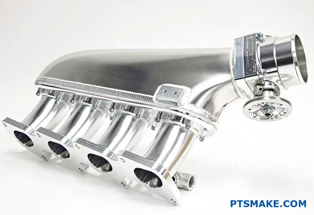
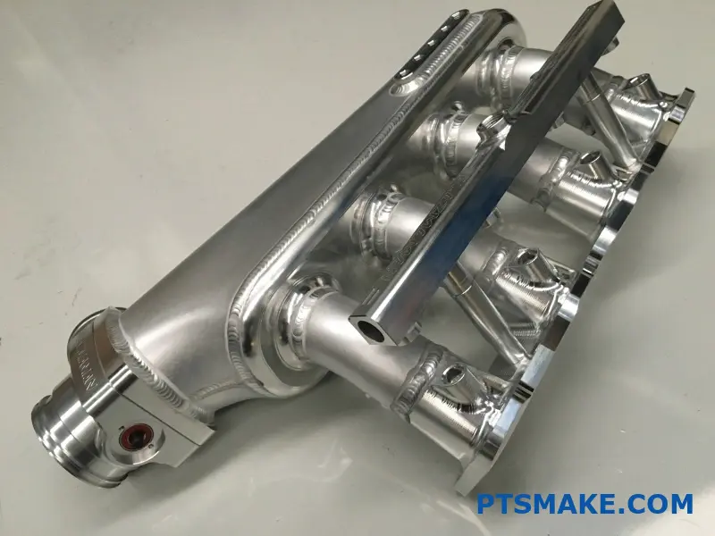
While stock manifolds are typically made from plastic or cast aluminum to reduce costs, custom versions utilize materials like:
| Material | Advantages | Best For |
|---|---|---|
| Billet Aluminum | Superior strength, excellent heat dissipation | High-performance applications |
| Carbon Fiber | Lightweight, good thermal insulation | Racing applications |
| Sheet Metal | Cost-effective customization, good for prototyping | Custom builds with tight budgets |
The material choice affects not just durability but also thermal characteristics. Cooler air is denser and contains more oxygen, which leads to more powerful combustion.
Runner Configuration
The runners (individual tubes leading to each cylinder) in custom manifolds are designed for specific power bands:
- Longer runners: Enhance low-end torque, ideal for street driving
- Shorter runners: Boost high-RPM horsepower, perfect for racing
- Variable length systems: Provide the best of both worlds
Some advanced custom designs incorporate velocity stacks at the runner entrances to smooth airflow transitions, reducing turbulence and improving cylinder filling efficiency.
Performance Benefits of Custom Intake Manifolds
Horsepower and Torque Gains
In my experience working with performance enthusiasts, a well-designed custom intake manifold can deliver power increases ranging from 10-30 horsepower depending on the engine and other modifications. This comes from the improved volumetric efficiency – essentially how effectively each cylinder can fill with air.
The torque curve can also be manipulated through manifold design. By changing runner lengths and plenum volume, the power delivery can be tailored to specific applications, whether that’s low-end grunt for towing or high-end power for track days.
Throttle Response
Many drivers notice improved throttle response immediately after installing a custom manifold. This comes from reduced restrictions in the airflow path and optimized runner designs that allow air to travel more directly to the cylinders.
Sound Characteristics
While not a performance metric in the strict sense, the change in intake sound is often dramatic with a custom manifold. The larger plenum volume and smoother pathways create a deeper, more aggressive induction noise that many enthusiasts appreciate. It’s what gives many high-performance engines their distinctive growl.
Who Needs a Custom Intake Manifold?
Not every vehicle will benefit significantly from a custom intake manifold. Based on projects I’ve overseen, these modifications make the most sense for:
- Competition vehicles where every horsepower matters
- Modified engines that have outgrown their stock airflow capacity
- Specialty builds where the stock manifold design restricts other modifications
- Engines with forced induction (turbochargers or superchargers) that need optimized airflow distribution
For daily drivers with otherwise stock engines, the cost-benefit ratio often doesn’t justify the expense. However, for those building performance-oriented vehicles, a custom intake manifold is often one of the most impactful naturally-aspirated performance modifications available.
Benefits of Plastic Intake Manifolds
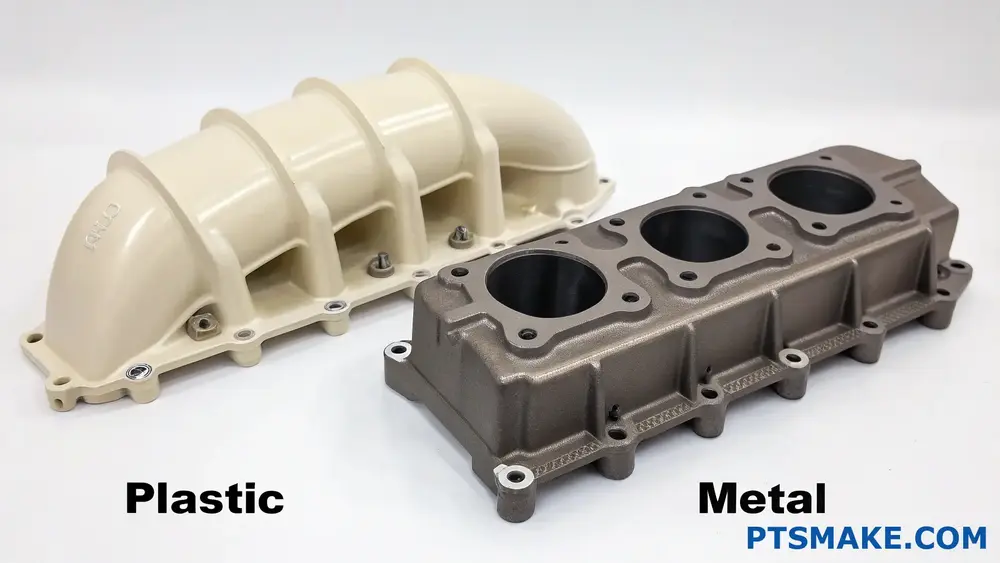
Have you ever wondered why modern vehicles increasingly use plastic intake manifolds instead of traditional metal ones? It’s a shift that’s changed engine design dramatically, yet many still question if plastic can truly outperform the time-tested metal components.
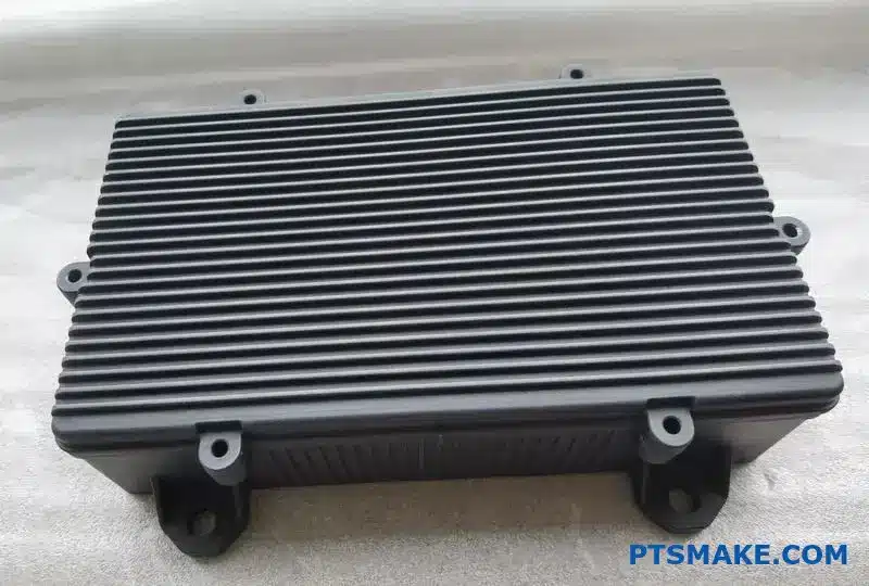
Plastic intake manifolds offer several advantages over metal versions including weight reduction, better fuel efficiency, improved airflow characteristics, lower production costs, and corrosion resistance. However, they may not match metal manifolds in heat resistance and durability under extreme conditions.
Weight Reduction – A Game Changer
The most significant advantage of plastic intake manifolds is their remarkable weight reduction. Depending on design complexity, plastic manifolds typically weigh 30-50% less than their metal counterparts. This weight difference might seem minor when looking at a single component, but it contributes significantly to a vehicle’s overall weight reduction strategy.
In my projects at PTSMAKE, I’ve seen how reducing an intake manifold’s weight by just a few pounds can create a cascade of benefits throughout a vehicle’s design. Engineers can achieve better weight distribution, improved fuel efficiency, and enhanced performance without compromising structural integrity.
Real-World Impact of Weight Savings
To put this in perspective, consider these weight comparisons:
| Material | Average Weight | Percentage Difference |
|---|---|---|
| Aluminum Manifold | 15-20 lbs (6.8-9.1 kg) | Baseline |
| Plastic Manifold | 5-10 lbs (2.3-4.5 kg) | 50-60% lighter |
This weight reduction directly impacts vehicle performance and efficiency metrics that consumers and regulators care about.
Thermal Insulation Properties
Plastic intake manifolds provide superior thermal insulation compared to metal versions. This insulation keeps incoming air cooler, which is crucial for engine performance. Cooler air is denser, containing more oxygen molecules per volume, which allows for more efficient combustion.
When I work with automotive engineers, they often highlight this thermal advantage as a key benefit. The thermal insulation coefficient2 of high-grade engineering plastics can be 500-1000 times higher than aluminum, resulting in intake air temperatures that are 10-15°C cooler at the combustion chamber.
Production Cost Advantages
From a manufacturing perspective, plastic manifolds offer substantial cost benefits:
- Lower material costs – Engineering plastics, despite being sophisticated materials, generally cost less than aluminum or other metals when considering the total production equation.
- Simplified production process – Injection molding allows for complex shapes in a single process, eliminating multiple assembly steps.
- Reduced finishing requirements – Plastic parts typically need minimal post-production finishing compared to cast metal components.
At PTSMAKE, our plastic injection molding capabilities allow us to produce complex manifold designs in a single shot, dramatically reducing production time and assembly costs for our clients.
Design Flexibility
The design freedom offered by plastic manifolds is perhaps their most underappreciated advantage. With injection molding technology, designers can create complex geometries that would be extremely difficult or prohibitively expensive with metal casting or fabrication.
This flexibility enables:
- Smoother internal flow passages
- Optimized runner designs
- Integrated features and mounting points
- Variable wall thicknesses for strength where needed
I’ve worked with design teams who completely rethought their intake manifold concepts once freed from the constraints of metal manufacturing. The ability to create organic, flow-optimized internal passages has led to performance improvements that simply weren’t possible with traditional metal designs.
Noise and Vibration Dampening
Another significant advantage of plastic manifolds is their natural ability to dampen noise and vibration. The material properties of engineered plastics absorb vibrations rather than transmitting them, unlike metals which can resonate and amplify these disturbances.
This dampening effect contributes to:
- Quieter engine operation
- Reduced noise in the passenger compartment
- Less stress on connecting components
- Improved overall NVH (Noise, Vibration, Harshness) characteristics
Our automotive clients frequently comment on how plastic manifolds have helped them meet increasingly stringent noise regulations without adding separate dampening systems.
Corrosion Resistance
Unlike metal manifolds which may corrode over time due to exposure to heat, moisture, and various chemicals present in the engine environment, plastic manifolds remain virtually impervious to corrosion. This resistance ensures consistent performance throughout the component’s lifespan and eliminates the need for protective coatings or treatments.
For vehicles operated in coastal regions or areas where road salt is common, this corrosion resistance can significantly extend the service life of the intake system compared to metal alternatives.
What Are The Advantages Of Plastic Intake Manifolds?
Have you ever wondered why so many modern vehicles use plastic intake manifolds instead of metal ones? It’s a question that puzzles many automotive enthusiasts and engineers alike. The shift from traditional metal to plastic seems counterintuitive in a high-temperature engine environment, yet manufacturers continue this trend.
Plastic intake manifolds offer significant advantages including weight reduction (up to 60% lighter than aluminum), cost efficiency, improved fuel economy, better thermal insulation, design flexibility, and smoother airflow characteristics. These benefits have made them the preferred choice for modern vehicle manufacturers.
Weight Reduction: A Game-Changer for Efficiency
When it comes to automotive design, weight is always a critical factor. Plastic intake manifolds provide remarkable weight savings compared to their metal counterparts. Typically, a plastic manifold weighs 40-60% less than an equivalent aluminum design and up to 80% less than cast iron versions.
This weight reduction directly contributes to overall vehicle performance in several ways:
Improved Fuel Efficiency: Every 100 pounds (45kg) removed from a vehicle can improve fuel economy by approximately 1-2%. When multiplied across millions of vehicles, this represents significant fuel savings.
Enhanced Performance: Lighter vehicles accelerate faster and handle better. Even small weight reductions in engine components can have noticeable effects on overall driving dynamics.
Reduced Emissions: Lighter vehicles require less energy to move, resulting in lower emissions – an increasingly important factor in today’s regulatory environment.
In my experience working with manufacturers, this weight advantage alone often justifies the switch to plastic manifolds in new vehicle designs.
Thermal Management Advantages
One seemingly contradictory benefit of plastic intake manifolds is their thermal management properties. Despite being used in high-temperature environments, plastics offer unique advantages:
Thermal Insulation
Plastic materials, particularly engineering-grade polymers like polyamide3, have inherently lower thermal conductivity than metals. This creates several benefits:
Cooler Air Intake: The insulating properties help maintain lower temperatures for incoming air, resulting in denser air charges and potentially improved power output.
Reduced Heat Transfer: Less heat transfers from hot engine components to the intake air, preventing performance-robbing intake air heating.
More Consistent Performance: Temperature stability leads to more predictable engine behavior across varying operating conditions.
Material Comparison for Thermal Conductivity
| Material | Thermal Conductivity (W/m·K) | Relative Insulating Property |
|---|---|---|
| Cast Iron | 50-80 | Very Poor |
| Aluminum | 120-235 | Poor |
| Nylon 6/6 with 30% Glass Fiber | 0.30 | Excellent |
| Nylon 6/6 with 33% Glass Fiber | 0.36 | Excellent |
This dramatic difference in thermal conductivity creates significant performance advantages in real-world applications.
Cost Efficiency Throughout the Value Chain
The economic benefits of plastic intake manifolds extend beyond just material costs:
Manufacturing Economies
- Lower Production Energy: Plastic molding typically requires less energy than metal casting or machining.
- Reduced Processing Steps: Metal manifolds often need additional machining, surface finishing, and corrosion protection.
- Integration Capabilities: Plastic manifolds can integrate components like sensors, water passages, and mounting brackets directly during molding, eliminating assembly steps.
Lifecycle Cost Benefits
From a total cost perspective, plastic manifolds often prove more economical over a vehicle’s lifetime. While the raw material cost may sometimes be higher than basic metals, the finished component cost typically favors plastic when all factors are considered.
In projects I’ve overseen at PTSMAKE, we’ve consistently found that properly designed plastic components provide better overall value when accounting for all aspects of production and performance.
Design Flexibility and Complexity
Perhaps the most compelling advantage of plastic intake manifolds is the design freedom they provide:
Complex Geometries
Modern intake manifold designs require complex flow paths to optimize engine breathing. Plastic molding technologies enable:
- Curved, organic shapes that would be extremely difficult to produce in metal
- Variable wall thicknesses to optimize strength where needed
- Intricate internal structures for flow management
- Seamless integration of mounting points and accessory features
Rapid Iteration and Customization
When working with automotive clients, I’ve found plastic manifolds allow for faster design iterations during development. The tooling modifications for plastic components are generally less costly and time-consuming than changes to metal casting molds, enabling more design refinement within project timelines.
Performance Benefits
Beyond the structural and manufacturing advantages, plastic intake manifolds can deliver notable performance improvements:
Flow Characteristics
The internal surface of plastic manifolds is inherently smoother than cast metal, creating less turbulence and friction for incoming air. Additionally, more complex runner designs can be created to:
- Balance airflow between cylinders
- Create resonance tuning effects for torque enhancement
- Optimize velocity profiles for better cylinder filling
Noise and Vibration Damping
Plastic materials naturally dampen vibrations better than metals, contributing to:
- Reduced engine noise transmission
- Less vibration-induced component stress
- Improved NVH (Noise, Vibration, Harshness) characteristics
- Enhanced driver comfort and perceived quality
Through consistent testing at PTSMAKE, we’ve documented how properly engineered plastic components can provide superior vibration damping compared to metal alternatives, often eliminating the need for additional sound-deadening materials.
Do Plastic Intake Manifolds Crack?
Have you ever heard that distinctive cracking sound under your hood, followed by rough idling or a sudden drop in performance? It’s a heart-stopping moment for any vehicle owner. Could your plastic intake manifold be giving up on you at the worst possible time?
Yes, plastic intake manifolds can crack due to heat cycling, manufacturing defects, improper installation, or aging. These cracks typically occur at stress points like mounting areas or near heat sources, causing performance issues like vacuum leaks, rough idling, and check engine lights.
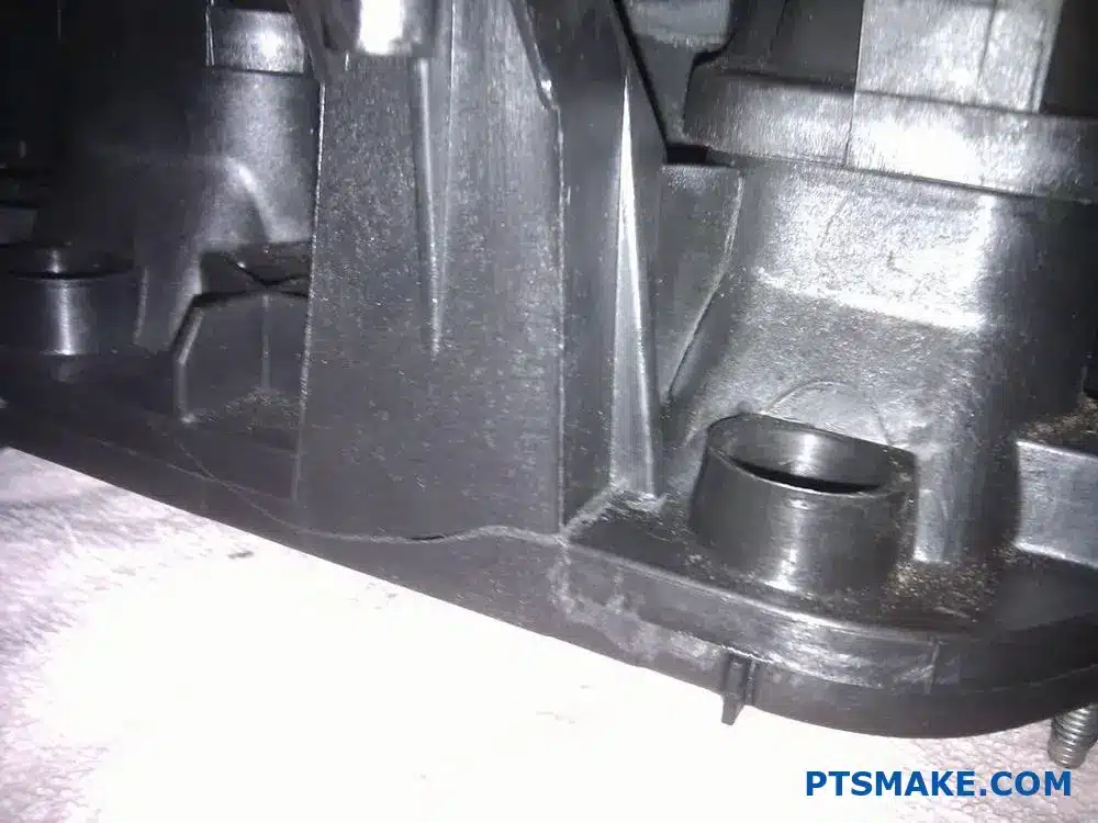
Common Locations for Plastic Intake Manifold Cracks
After examining hundreds of damaged intake manifolds, I’ve identified several vulnerability hotspots where cracks most frequently develop:
Mounting Points and Fastener Areas
The areas around bolts and mounting points experience significant mechanical stress during installation and operation. These points become natural weak spots where cracks can initiate, especially if:
- Bolts were overtightened during installation
- The manifold was subjected to uneven pressure
- Temperature fluctuations caused expansion and contraction
Runner Junctions
The intersections where runners meet the plenum are particularly vulnerable to stress concentration. In my experience at PTSMAKE, we’ve found that these junctions often develop stress risers4 – points where mechanical force multiplies – leading to crack formation under thermal cycling.
Throttle Body Mount
This high-heat area experiences both thermal and mechanical stress. The transition between the plastic manifold and metal throttle body creates a perfect scenario for crack development, especially in older vehicles where the plastic has become brittle.
What Causes Plastic Intake Manifolds to Crack?
Understanding the root causes helps prevent premature failure:
Thermal Cycling
The engine compartment experiences extreme temperature variations – from below freezing to over 200°F (93°C). This repeated heating and cooling causes the plastic to expand and contract. Over time, this leads to material fatigue and eventually cracking.
Material Degradation
Not all plastics are created equal. Lower-quality plastics used in some aftermarket manifolds deteriorate faster. I’ve observed that manifolds made from high-quality nylon 6/6 with glass fiber reinforcement consistently outlast their cheaper counterparts.
Manufacturing Defects
Even small flaws in the molding process can create weak points:
| Defect Type | Description | Impact on Durability |
|---|---|---|
| Air Bubbles | Trapped air during injection molding | Creates internal weak points |
| Weld Lines | Where plastic flows meet during molding | Reduced structural integrity |
| Sink Marks | Depressions from uneven cooling | Thinner material at these points |
| Uneven Wall Thickness | Inconsistent material distribution | Stress concentration areas |
Improper Installation
Over-torquing fasteners is a leading cause of premature cracking. I’ve seen technicians crack brand new manifolds simply by not following torque specifications. Always use a torque wrench and follow the sequence specified in your repair manual.
Warning Signs of a Cracked Intake Manifold
Identifying problems early can save you from expensive engine damage:
- Check Engine Light – Often the first indicator, particularly codes related to vacuum leaks or lean conditions
- Rough Idle – Unmetered air entering through cracks causes erratic idle
- Poor Performance – Decreased power and responsiveness
- Unusual Sounds – Hissing or whistling noises, especially under acceleration
- Failed Emissions Tests – Unburned fuel or improper air-fuel ratios
- Visible Coolant Leaks – For manifolds with integrated coolant passages
Prevention and Solutions
Based on my engineering experience, here are practical steps to prevent and address manifold cracks:
Preventive Measures
- Follow proper torque specifications during installation
- Allow proper warm-up time before hard acceleration
- Perform regular visual inspections of the manifold
- Consider upgrading to reinforced aftermarket designs for known problem vehicles
Repair Options
For minor cracks, specialized epoxy designed for high-temperature applications can provide a temporary solution. However, this should be considered a short-term fix until proper replacement.
Replacement Considerations
When replacing a cracked manifold, consider these options:
- OEM Replacement: Ensures proper fit but may replicate the original design flaws
- Upgraded Aftermarket: Often incorporates improved materials and design features
- Custom Intake Manifolds: For performance applications, custom manifolds from precision manufacturers can optimize both durability and performance
At PTSMAKE, we’ve helped numerous clients develop custom intake manifolds with enhanced durability features, including optimized wall thickness, reinforced mounting points, and superior material selection.
Material Selection for Durable Plastic Manifolds
The choice of polymer significantly impacts durability:
- Nylon 6/6 with 30-35% Glass Fiber: Excellent heat resistance and dimensional stability
- PPA (Polyphthalamide): Superior chemical and heat resistance
- PPS (Polyphenylene Sulfide): Exceptional thermal stability and chemical resistance
- PEEK (Polyether Ether Ketone): Premium option with outstanding temperature resistance
Proper material selection must balance cost considerations with performance requirements, especially when designing custom intake manifolds for specific applications.
How Much HP Does A Good Intake Manifold Add?
Have you ever floored the gas pedal on your car and felt that it could be more responsive? Or wondered why your engine seems to lack that extra punch despite all the other upgrades you’ve made? The answer might be hiding in your intake manifold – a crucial component many enthusiasts overlook.
A good aftermarket intake manifold typically adds between 15-35 horsepower to your engine. The exact gains depend on your engine type, the quality of the manifold, and how well it matches your specific setup. Custom intake manifolds can sometimes deliver even higher gains when properly designed.
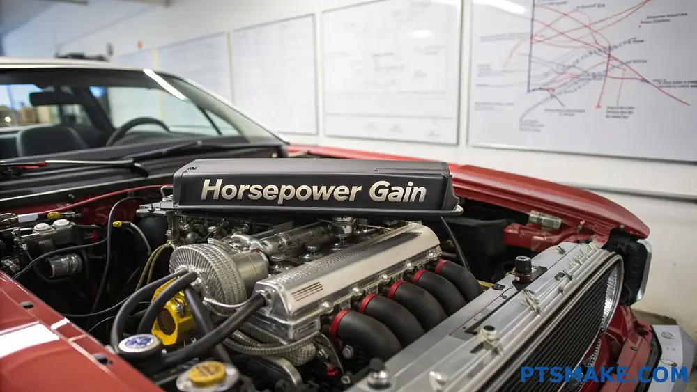
Understanding Intake Manifold Horsepower Gains
When it comes to boosting engine performance, intake manifolds are often underappreciated heroes. I’ve tested countless manifolds over the years and found that their impact on horsepower varies widely based on several factors.
The primary mechanism for power gains comes from how efficiently air flows into your cylinders. Factory intake manifolds are designed with compromises – they need to work reasonably well across various driving conditions while meeting emissions standards and keeping costs down. Aftermarket manifolds focus specifically on performance, optimizing the air delivery system for maximum power.
Realistic Horsepower Expectations by Engine Type
Different engines respond differently to intake manifold upgrades:
| Engine Type | Typical HP Gain | Optimal Manifold Design |
|---|---|---|
| 4-cylinder | 10-20 HP | Short runner designs with tuned plenum volume |
| V6 | 15-25 HP | Medium runner length with balanced flow distribution |
| V8 | 20-35 HP | Longer runners for torque, shorter for peak HP |
| Forced Induction | 25-40+ HP | Larger plenum volume with reinforced construction |
These numbers aren’t just theoretical. I’ve seen a well-matched intake manifold add 32 horsepower to a naturally-aspirated V8 during dyno testing at our facility. The key was selecting a design that complemented the engine’s existing breathing characteristics.
Factors That Influence Manifold Performance Gains
The actual power increase you’ll experience depends on several variables:
Runner Design and Length: Longer runners typically improve low-end torque while shorter runners enhance top-end horsepower. The ideal length depends on your power goals and engine’s operating range.
Plenum Volume: The air chamber size significantly impacts how your engine breathes. A larger plenum often benefits higher-RPM applications, while a smaller one can improve throttle response.
Material Choice: Aluminum manifolds dissipate heat better than plastic ones, potentially providing more consistent performance during extended high-load driving.
Port Matching: How well the manifold’s ports align with your cylinder head is crucial. Volumetric efficiency5 increases dramatically when ports are properly matched and flow is optimized.
The Cost-to-Power Ratio Analysis
When advising clients on performance upgrades, I always emphasize value. Intake manifolds often provide excellent returns on investment compared to other modifications.
A quality aftermarket intake manifold typically costs between $400-$1,200, depending on the materials, design complexity, and brand reputation. When you consider the potential 15-35 horsepower gain, you’re looking at roughly $25-40 per horsepower – significantly better than many other engine modifications.
Custom manifolds may cost more (usually $1,500-$3,000) but can be tailored to your specific setup, potentially delivering even greater gains. For serious performance enthusiasts, this customization can make perfect sense, especially when integrated with other engine modifications.
Comparing Intake Manifolds to Other Power Upgrades
To put intake manifold improvements in perspective:
| Modification | Typical Cost | Average HP Gain | Cost Per HP |
|---|---|---|---|
| Intake Manifold | $400-$1,200 | 15-35 HP | $25-40/HP |
| Performance Exhaust | $500-$1,500 | 5-20 HP | $75-100/HP |
| ECU Tune | $300-$700 | 10-25 HP | $30-70/HP |
| Camshafts | $800-$2,000 | 20-50 HP | $40-80/HP |
| Turbo Upgrade | $2,000-$5,000 | 50-150 HP | $33-50/HP |
As you can see, intake manifolds offer compelling value when compared to other common power-adding modifications. They also typically require less labor to install than camshafts or turbo systems, further enhancing their value proposition.
Real-World Performance Impacts Beyond Dyno Numbers
While horsepower numbers are important, the actual driving experience matters more. A well-designed intake manifold can transform how your car feels in ways that extend beyond peak horsepower figures:
- Improved throttle response: Many drivers notice more immediate power delivery, especially in the mid-range RPMs
- Broader powerband: Good manifolds can extend your effective power range, making the car more drivable
- Enhanced engine sound: The altered intake resonance often creates a more aggressive engine note under acceleration
- Better fuel atomization: Some designs improve the air-fuel mixture, potentially enhancing both power and efficiency
At PTSMAKE, we’ve helped develop custom intake solutions for several performance applications, and the feedback consistently highlights these real-world improvements that dynamometer numbers don’t fully capture.
What Role Does Custom Runners and Plenums Play in Engine Performance?
Have you ever floored the gas pedal only to be disappointed by your engine’s lackluster response? Or spent thousands on performance mods but still can’t achieve that perfect power curve? The frustration of unrealized performance potential often lies hidden within your intake manifold’s runners and plenum design.
Custom runners and plenums dramatically influence engine performance by controlling airflow dynamics, optimizing resonance tuning, and managing air distribution to cylinders. Properly designed runners create pressure waves that enhance cylinder filling, while well-engineered plenums ensure balanced air delivery across all cylinders, significantly boosting overall engine output.

The Science Behind Runner Length and Diameter
When designing custom intake manifolds, understanding how runner geometry affects airflow is essential. I’ve found that runner length and diameter create a delicate balance that can make or break engine performance.
Runner Length: Tuning for RPM Response
Runner length directly impacts where in the RPM range your engine develops maximum torque. This relationship stems from pressure wave dynamics6 that occur within the intake tract. As the intake valve closes, a negative pressure wave travels back up the runner. When this wave reaches the plenum, it reflects back as a positive pressure wave.
Longer runners produce stronger low-end torque because the pressure waves return at the perfect timing for lower RPM operation. When I design manifolds for trucks or heavy equipment, I typically recommend longer runners. Conversely, shorter runners favor high-RPM power, making them ideal for racing applications where peak horsepower at high engine speeds is the priority.
Runner Diameter: Balancing Velocity and Volume
Runner diameter creates another critical tuning parameter. Smaller diameters increase air velocity, which improves cylinder filling at lower RPMs by maintaining higher kinetic energy in the airflow. However, they can become restrictive at higher engine speeds.
Larger diameters permit greater airflow volume but may reduce velocity. At PTSMAKE, when manufacturing performance manifolds, we often implement a tapered runner design, starting narrower at the plenum and widening toward the cylinder head. This progressive design helps maintain velocity while accommodating higher airflow demands.
Plenum Design Considerations
The plenum serves as the central air distribution chamber in your intake manifold. Its design significantly impacts how evenly air reaches each cylinder.
Volume and Shape Effects
A properly sized plenum acts as a buffer, ensuring adequate air supply to all cylinders under varying conditions. Through testing numerous designs, I’ve learned that plenum volume typically needs to be 50-80% of your engine’s displacement for optimal performance across a wide RPM range.
The plenum shape matters just as much as its size. I recommend designs that minimize turbulence and directional bias. For V-configuration engines, a central plenum with symmetrical runner entries helps ensure balanced air distribution. For inline engines, a longitudinal design often works best.
Equal vs. Tuned Length Runners from Plenum
There are two primary philosophies in runner configuration:
| Configuration | Advantages | Best Applications |
|---|---|---|
| Equal Length | Balanced power delivery, consistent torque curve | Street performance, endurance racing |
| Tuned Length | Optimized for specific RPM targets, potential for higher peak power | Specialized racing, drag applications |
Equal length runners ensure each cylinder receives similar airflow characteristics, promoting balanced combustion across all cylinders. Tuned length designs sacrifice some balance to target specific performance goals.
Material Selection Impact
The material used in your intake manifold affects both performance and durability. Different materials offer various benefits:
Thermal Properties and Engine Performance
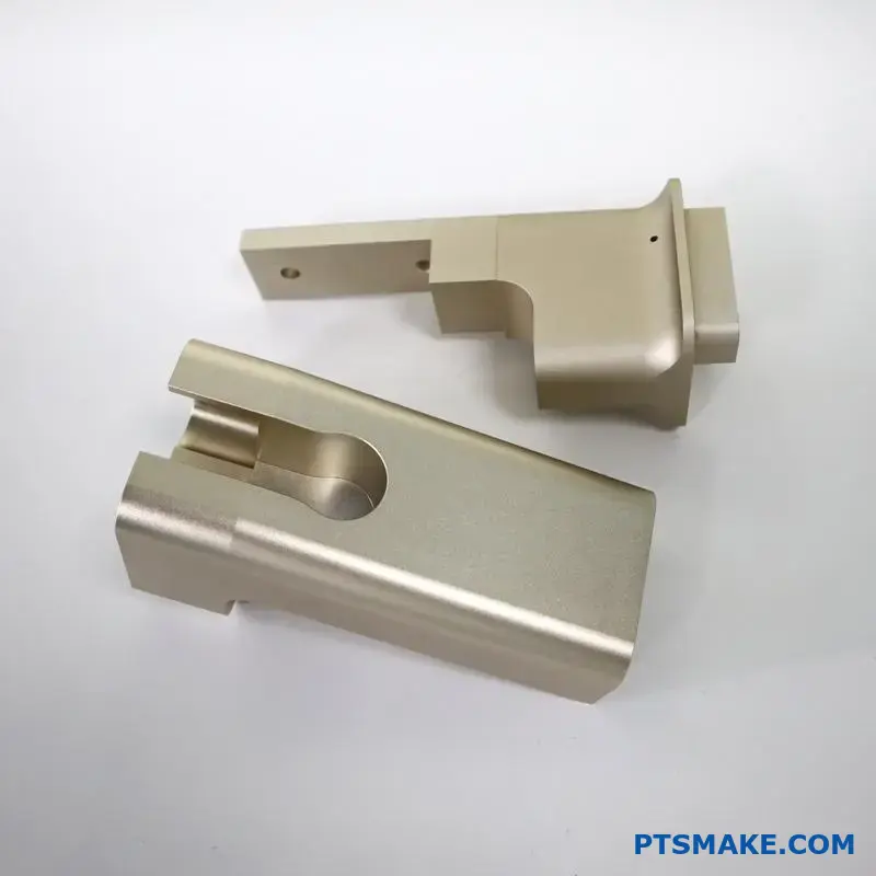
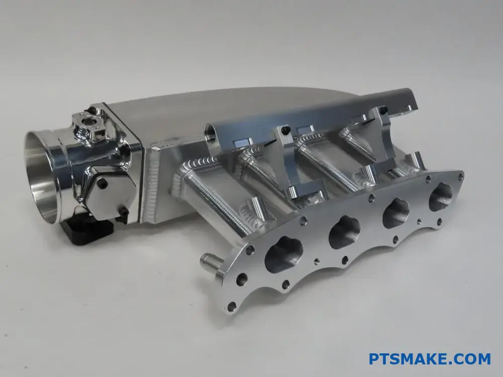
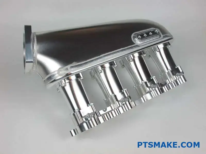
Aluminum remains the industry standard due to its excellent balance of weight, thermal conductivity, and cost. At PTSMAKE, we use precision CNC machining to create aluminum manifolds with complex internal geometries that would be impossible with traditional casting methods.
Composite materials are gaining popularity for their superior thermal insulation properties. A cooler intake charge is denser, containing more oxygen molecules per volume. In testing, I’ve seen properly designed composite manifolds provide a 5-15°F reduction in intake temperatures compared to aluminum, resulting in measurable performance gains.
Durability and Manufacturing Considerations
For high-boost applications, material strength becomes critical. Our manufacturing process allows for reinforced designs in high-stress areas, particularly around mounting points and plenum-to-runner transitions where pressure fluctuations are greatest.
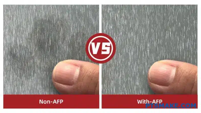
Surface finish within the runners also impacts performance. Through years of testing, I’ve found that moderately smooth surfaces with controlled texture patterns can actually improve airflow characteristics compared to mirror-finished passages, which may seem counterintuitive to some engineers.
Real-World Performance Impacts
The theoretical benefits of custom runner and plenum designs translate to measurable performance gains. Working with racing teams, I’ve seen properly optimized intake manifolds deliver:
- 5-10% increases in peak torque
- 3-8% improvements in horsepower
- Enhanced throttle response
- More consistent cylinder-to-cylinder air/fuel ratios
For street applications, the most noticeable improvement typically comes in mid-range torque, which enhances drivability and everyday performance. For racing applications, the ability to precisely target power delivery to specific RPM ranges can provide a competitive advantage on particular tracks or driving conditions.
What Does A Better Intake Manifold Do?
Have you ever stepped on the gas pedal only to feel your engine hesitate or lack power? Or wondered why your car doesn’t perform as well as the same model you test drove? These frustrating moments often trace back to one critical component that many overlook: the intake manifold.
A better intake manifold improves engine performance by optimizing airflow distribution to all cylinders, increasing horsepower, enhancing torque, and improving fuel efficiency. Quality manifolds reduce turbulence, minimize pressure drops, and ensure even air-fuel mixture delivery throughout the engine’s RPM range.
How Intake Manifold Design Affects Engine Performance
The intake manifold is far more than just a set of tubes connecting your air filter to the engine. It’s an engineered system that significantly impacts how your engine breathes and performs. In my experience working with performance vehicles, I’ve found that manifold design is one of the most influential factors in optimizing engine output.
The primary function of an intake manifold is to evenly distribute the air-fuel mixture to each cylinder. However, the way this distribution happens affects everything from power output to fuel economy. A well-designed manifold creates a laminar flow7 of air rather than turbulent movement, which helps maintain consistent pressure across all cylinders.
When comparing stock manifolds to performance versions, the differences become clear:
| Feature | Stock Manifold | Performance Manifold |
|---|---|---|
| Runner Length | Typically compromised for packaging | Optimized for target RPM range |
| Runner Diameter | Uniform | Tuned for specific cylinders |
| Internal Surface | Often rough casting | Smooth, polished surfaces |
| Plenum Volume | Restricted by space | Engineered for airflow needs |
| Material | Usually plastic or cast iron | Aluminum, carbon fiber, composite |
The Science Behind Intake Manifold Improvements
Runner Geometry and Tuning
The "runners" (the tubes that connect the plenum to each cylinder intake port) play a critical role in engine performance. Their length and diameter create resonance effects that can significantly boost torque at specific RPM ranges.
Shorter runners generally favor high-RPM power, while longer runners enhance low-end torque. This is why some advanced intake manifolds feature variable-length runners that can adjust based on engine speed.
The diameter of these runners also matters tremendously. Too narrow, and they restrict airflow at high RPM; too wide, and you lose the velocity needed for good low-end response. Custom intake manifolds can be designed with the perfect runner dimensions for your specific engine and performance goals.
Plenum Design Considerations
The plenum chamber (the central volume where air enters before being distributed to runners) requires careful engineering. Its volume and shape determine how effectively air can be distributed, especially during quick throttle changes.
A larger plenum generally supports higher horsepower at higher RPMs by providing a greater air reservoir. However, an oversized plenum can reduce air velocity and hurt throttle response. The ideal plenum size balances these factors based on engine displacement and intended use.
Material Choices and Their Impact
The material used in manifold construction affects performance in several ways:
Thermal Properties
Cast iron manifolds retain heat, which can pre-warm incoming air. While this helps with cold starts, it reduces air density and power potential. Aluminum manifolds dissipate heat better, keeping incoming air cooler and denser. This is why you’ll often see heat shields or thermal barriers on performance manifolds.
In high-performance applications, composite or carbon fiber manifolds offer even better thermal insulation, maintaining the lowest possible air intake temperatures.
Weight Considerations
Lighter materials not only improve overall vehicle weight but also affect throttle response. Reducing reciprocating and rotating mass in an engine system creates more responsive power delivery. Aluminum typically weighs about one-third as much as cast iron, while composite materials can be even lighter.
Real-World Benefits of Upgraded Intake Manifolds
In my testing with clients’ vehicles, properly designed aftermarket intake manifolds consistently provide:
- Power gains of 5-15 horsepower, depending on engine type and other modifications
- Improved throttle response across the RPM range
- More consistent power delivery, especially in multi-cylinder engines
- Enhanced fuel economy under normal driving conditions
- Better sound quality (the intake harmonics often become more aggressive)
For daily drivers, these improvements translate to more confidence during highway merging, better passing ability, and often a slight improvement in fuel economy during steady cruising.
For performance vehicles, a custom intake manifold becomes almost essential when other modifications like camshafts, exhaust systems, or forced induction are installed. Without matching the intake flow characteristics to these other components, you might be leaving significant performance on the table.
How To Choose The Right Manufacturing Process For Custom Intake Manifolds?
Ever found yourself stuck between multiple manufacturing options for your custom intake manifold project? Have you watched costs spiral or timelines stretch because you selected the wrong production method? Choosing incorrectly can mean the difference between race-winning performance and expensive paperweights sitting on your shelf.
Selecting the right manufacturing process for custom intake manifolds requires balancing factors like production volume, material requirements, budget constraints, and performance needs. Each method—from casting and CNC machining to 3D printing—offers distinct advantages for different applications, making this decision crucial to your project’s success.

Evaluating Your Production Volume Needs
When selecting a manufacturing process for custom intake manifolds, production volume is often my first consideration. The right approach varies dramatically depending on whether you’re building a one-off prototype or planning a production run of thousands.
Low Volume Production Considerations
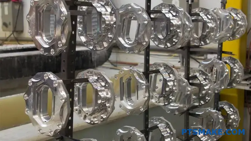
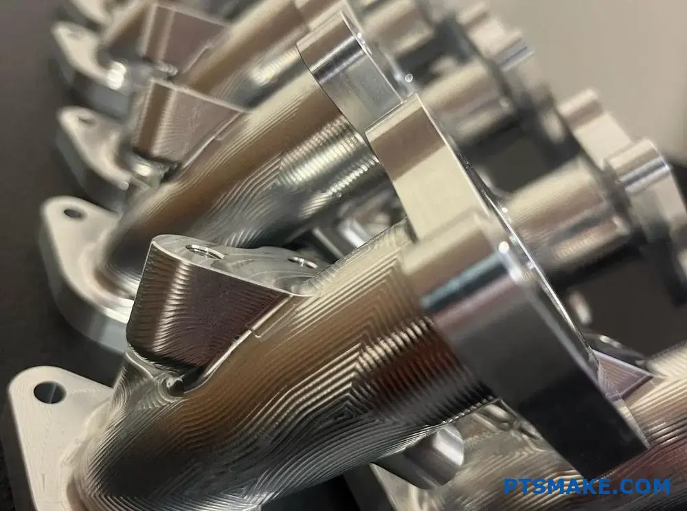
For prototypes or limited production runs (typically under 10-50 units), flexible manufacturing processes make more economic sense. In my experience at PTSMAKE, CNC machining and 3D printing excel here:
- CNC Machining: Offers excellent precision without expensive tooling investments, perfect for small batches of high-performance manifolds
- 3D Printing: Provides rapid turnaround with complex internal geometries that would be impossible with traditional methods
High Volume Manufacturing Options
When production quantities exceed 100+ units, the economics shift dramatically. Initial tooling investments become justified by the per-unit cost savings:
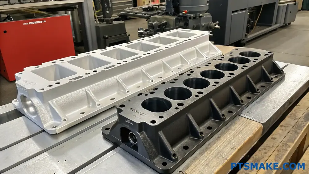
- Casting Methods: Die casting and investment casting become economically viable at higher volumes
- Injection Molding: For composite or polymer manifolds, this offers exceptional consistency at scale
Material Selection Considerations
Material selection directly influences which manufacturing process will deliver optimal results for your custom intake manifold.
Metals and Their Compatible Processes
Aluminum remains the dominant material for performance intake manifolds due to its excellent heat dissipation and weight characteristics. Different aluminum alloys pair with specific manufacturing techniques:
| Material | Optimal Manufacturing Process | Key Advantages | Limitations |
|---|---|---|---|
| Aluminum 6061 | CNC Machining | Excellent machinability, good strength | Higher cost per unit |
| Aluminum A356 | Die Casting | Excellent for high-volume production | Significant tooling investment |
| Aluminum 7075 | CNC Machining | Superior strength-to-weight ratio | Higher material cost |
| Magnesium Alloys | Die Casting | Lightest metal option, better vibration dampening | More specialized processing |
Composite and Polymer Options
For certain applications, composite materials offer compelling alternatives:
- Carbon Fiber Composites: Typically manufactured through hand layup or compression molding
- High-Temperature Polymers: Can be injection molded when temperature requirements allow
Complexity vs. Manufacturability Analysis
The geometric complexity8 of your intake manifold design will significantly narrow your manufacturing options. Complex internal runner shapes, variable wall thicknesses, and intricate flow optimization features all impact manufacturability.
Assessing Design Complexity
I’ve found the following complexity factors directly influence process selection:
- Internal Passages: Complex curved internal geometries may eliminate certain casting methods
- Wall Thickness Variations: Processes like die casting have limitations on wall thickness transitions
- Surface Finish Requirements: CNC typically offers superior surface finish compared to casting methods
- Undercuts and Internal Features: May require multi-part molds or alternative approaches
Manufacturing Process Capabilities Matrix
After evaluating hundreds of custom intake manifold projects, I’ve developed this capability matrix to guide process selection:
| Feature Complexity | CNC Machining | Die Casting | 3D Printing | Investment Casting |
|---|---|---|---|---|
| Complex Internal Runners | Limited | Good | Excellent | Good |
| Thin Wall Sections | Limited | Excellent | Good | Good |
| Precision Tolerance | Excellent | Good | Moderate | Good |
| Surface Finish | Excellent | Good | Poor-Moderate | Good |
| Design Iteration Speed | Moderate | Poor | Excellent | Poor |
Balancing Performance and Cost Considerations
The ultimate goal is finding the optimal balance between performance, cost, and timeline requirements. At PTSMAKE, we often recommend a hybrid approach for certain projects.
Cost Structure Breakdown by Process
Understanding the cost structure of each manufacturing process helps make informed decisions:
- CNC Machining: Higher per-unit costs but minimal setup costs
- Die Casting: High initial tooling investment but low per-unit costs at volume
- 3D Printing: Moderate unit costs with minimal setup, but slower production rates
- Investment Casting: Moderate tooling costs with good per-unit economics at medium volumes
For specialized applications where absolute performance is critical, CNC machining often remains the gold standard despite higher unit costs. The precision and material options available through precision machining simply can’t be matched by other processes in certain high-performance scenarios.
Timeline and Production Scheduling Factors
In today’s competitive market, time-to-production often rivals cost and performance in importance. Each manufacturing process offers different lead time expectations:
- CNC Machining: 1-3 weeks typical lead time
- Die Casting: 8-12 weeks for tooling plus production time
- 3D Printing: Days to weeks depending on complexity and finishing requirements
- Investment Casting: 4-8 weeks typical lead time
When evaluating your manufacturing options, consider not just the immediate project but your long-term production strategy. The right manufacturing partner should help navigate these complex decisions, providing insights based on your specific requirements rather than pushing a one-size-fits-all solution.
What Tolerances Are Achievable With CNC-Machined Custom Intake Manifolds?
Ever struggled with intake manifolds that just don’t perform as expected? Have you invested in custom manifolds only to find that tiny tolerance issues created massive performance gaps? The difference between championship performance and mediocrity often comes down to fractions of a millimeter in critical engine components.
With CNC-machined custom intake manifolds, achievable tolerances typically range from ±0.025mm to ±0.1mm (0.001" to 0.004") depending on material, design complexity, and machining strategy. These precision levels ensure optimal airflow distribution, consistent engine performance, and proper sealing against leaks.
Understanding Tolerance Requirements for Intake Manifolds
When designing custom intake manifolds, tolerance requirements vary based on several factors. The most critical areas include mounting surfaces, runner connections, plenum junctions, and sensor ports. Each area demands specific tolerance levels to ensure proper functionality.
For mounting surfaces that connect to the cylinder head, I typically recommend tolerances of ±0.05mm (±0.002"). This precision ensures proper sealing and prevents air leaks that could compromise engine performance. The flatness tolerance for these surfaces should be maintained within 0.025mm per 100mm length to avoid warping issues.
Runner dimensions require tolerances of ±0.1mm (±0.004") for diameter and length. While this might seem loose compared to other engine components, these tolerances still allow for consistent airflow characteristics across cylinders. The internal surface finish should be maintained at Ra 1.6-3.2 μm to reduce friction losses and optimize flow.
Material-Specific Tolerance Considerations
Different materials react differently during machining, affecting achievable tolerances:
| Material | Typical Achievable Tolerance | Notes |
|---|---|---|
| Aluminum | ±0.025mm to ±0.05mm | Excellent machinability, stable during processing |
| Steel | ±0.05mm to ±0.1mm | Higher cutting forces, potential for tool deflection |
| Polymer/Composite | ±0.1mm to ±0.2mm | Thermal expansion concerns, tool wear issues |
Aluminum alloys like 6061-T6 or 7075 are my preferred choices for custom intake manifolds due to their excellent machinability and dimensional stability. When working with these materials at PTSMAKE, we consistently achieve tolerances as tight as ±0.025mm on critical features without specialized techniques.
Critical Features Requiring Tighter Tolerances
Sealing Surfaces
The most demanding tolerance requirements apply to sealing surfaces. For proper gasket compression, these surfaces need flatness tolerances of 0.025mm across their entire area. Any deviation beyond this can create leak paths, especially under high-pressure conditions.
The surface finish on sealing faces is equally important. I recommend Ra 0.8-1.6 μm to ensure proper gasket seating and compression. Achieving this finish requires careful selection of cutting tools and machining parameters.
Throttle Body Mounting Interfaces
Throttle body connections represent another critical area where precision matters. These interfaces typically require:
- Diameter tolerances of ±0.025mm (±0.001")
- Perpendicularity to manifold base of 0.05mm
- True position tolerance of 0.1mm
These tight tolerances ensure proper throttle body alignment and prevent uneven airflow distribution or vacuum leaks that could affect idle quality and throttle response.
Advanced CNC Techniques for Higher Precision
To achieve the tightest tolerances on custom intake manifolds, several specialized CNC techniques come into play:
Temperature-Controlled Machining Environment
One often overlooked factor is thermal stability. Metal expands and contracts with temperature changes, which can impact dimensional accuracy. In our CNC facility, we maintain temperature-controlled environments (21±1°C) for high-precision manifold machining.
Multi-Axis Simultaneous Machining
Five-axis simultaneous machining allows complex internal geometries to be created with minimal setups. This approach reduces accumulated error9 from multiple setups and enables better surface finish on complex curved runner surfaces.
In-Process Measurement and Adaptive Machining
For the most demanding applications, in-process measurement systems can verify dimensions during machining. When deviations are detected, the CNC program automatically adjusts to compensate, ensuring final tolerances are maintained regardless of tool wear or thermal effects.
Real-World Tolerance Challenges
Despite advances in CNC technology, certain intake manifold features still present tolerance challenges:
- Deep internal runners – As depth increases, tool deflection becomes more significant
- Complex plenum shapes – Compound curves require multi-axis approaches to maintain uniform tolerances
- Thin wall sections – Vibration during machining can cause tolerance deviations
- Threaded connections – Maintaining thread pitch diameter tolerances for sensor ports
When designing custom manifolds, I always recommend simplifying geometries where possible without compromising performance. This approach allows for more consistent manufacturing tolerances and better long-term reliability.
Tolerance Stack-Up Considerations
One often overlooked aspect of manifold design is tolerance stack-up. When multiple features interact, their individual tolerances combine, potentially creating fit issues. For instance, a manifold with eight mounting holes could experience significant position errors at the extremes if tolerances aren’t properly controlled.
At PTSMAKE, we utilize geometric dimensioning and tolerancing (GD&T) principles to manage these stack-ups effectively. By applying true position tolerances referenced to key datums, we ensure proper alignment even with multiple features.
Cost vs. Precision Balancing Act
There’s always a trade-off between manufacturing cost and achievable tolerance. While CNC machining can theoretically achieve tolerances below ±0.01mm, the cost increases exponentially as tolerances tighten:
| Tolerance Range | Relative Cost | Application Suitability |
|---|---|---|
| ±0.1mm | Base cost | Non-critical features, general dimensions |
| ±0.05mm | 1.5-2x base | Standard sealing surfaces, mounting interfaces |
| ±0.025mm | 2-3x base | Critical sealing surfaces, precision fit areas |
| ±0.01mm | 4-5x base | Rarely required for intake manifolds |
For most custom intake manifold applications, targeting ±0.05mm for critical features provides the optimal balance between performance and manufacturing cost. This level ensures proper function while keeping projects economically viable.
How Does Material Selection Impact The Cost Of Custom Intake Manifold Production?
Ever wondered why two seemingly similar intake manifolds can have drastically different price tags? Have you been caught off guard by unexpected costs when switching materials for your manifold project? The difference often lies not just in the material itself, but in how that choice cascades through the entire production process.
Material selection is the single most influential factor in custom intake manifold costs. Different materials require specific tooling, machining techniques, and post-processing. While aluminum offers a cost-effective balance at $300-600, carbon fiber commands $800-1,500 due to complex manufacturing processes, and specialty alloys can exceed $1,000 due to difficult machinability.
Key Materials and Their Cost Implications
When developing custom intake manifolds, the material choice fundamentally shapes both performance characteristics and production costs. Based on my experience working with various automotive and performance clients, I’ve observed several critical cost factors associated with different materials.
Aluminum Alloys: The Cost-Effective Standard
Aluminum alloys (particularly 6061 and 6063) represent the industry standard for many good reasons. These materials strike an excellent balance between performance, manufacturability, and cost-effectiveness.
From a production standpoint, aluminum offers several cost advantages:
- Relatively easy to machine compared to harder metals
- Excellent thermal conductivity that prevents warping during machining
- Good surface finish without extensive post-processing
- Readily available in various forms and dimensions
The typical cost range for custom aluminum intake manifolds falls between $300-600 depending on complexity. This affordability makes aluminum the go-to choice for most production vehicles and many aftermarket applications.
Composite Materials: Higher Cost for Weight Reduction
Carbon fiber and other composite materials have gained popularity, especially in high-performance applications where weight reduction is paramount. However, this performance advantage comes with substantial cost implications:
- Complex manufacturing processes involving manual layup
- Expensive raw materials (carbon fiber can cost 5-10x more than aluminum)
- Specialized tooling and equipment requirements
- Longer production cycles with additional curing time
The resulting price point for carbon fiber intake manifolds typically ranges from $800-1,500, representing a significant premium over aluminum alternatives.
Specialty Metals: Premium Pricing for Specific Properties
Materials like titanium, stainless steel, and specialty alloys occupy a premium segment of the market. Their cost implications include:
- Difficult machinability requiring specialized tooling
- Higher raw material costs
- Increased machining time due to material hardness
- Additional heat management during manufacturing
- More frequent tool replacement
These factors drive the cost of specialty metal intake manifolds to $1,000+ for even relatively simple designs. The metallurgical characteristics10 of these materials often justify the expense for specific high-stress applications.
Production Process Variations by Material
The manufacturing approach varies significantly based on material selection, directly impacting the final cost structure.
Aluminum Production Methods
| Method | Cost Impact | Typical Applications |
|---|---|---|
| CNC Machining | Moderate ($300-500) | Prototypes, small production runs |
| Cast & Machine | Lower for volume ($200-400) | Production vehicles, aftermarket |
| Extrusion & Welding | Lowest ($150-300) | Simple geometry manifolds |
At PTSMAKE, we’ve optimized our CNC operations for aluminum, allowing us to offer competitive pricing while maintaining tight tolerances that ensure proper airflow characteristics.
Composite Manufacturing Approaches
Composite materials require entirely different production methodologies:
- Hand Layup – Most expensive, used for one-off prototypes
- Vacuum Infusion – Mid-range cost, better consistency
- Resin Transfer Molding – Lower per-unit cost but high initial tooling investment
Each method presents different cost structures. The tooling investment alone for composite manifolds typically exceeds the entire production cost of an aluminum counterpart.
Specialty Metal Production Considerations
When working with titanium or high-strength steel alloys, the production process requires specialized approaches:
- Slower cutting speeds to prevent work hardening
- More frequent tool changes (increasing machine downtime)
- Additional cooling requirements
- More complex fixturing to manage material movement
These factors can double or triple the machining time compared to aluminum, with a corresponding impact on costs.
Cost-Saving Strategies Through Material Selection
Making informed material choices can help control costs without compromising performance:
- Material Hybridization – Using premium materials only where necessary
- Volume Optimization – Designing for material-specific manufacturing constraints
- Surface Treatment Alternatives – Using coatings to enhance base material properties
For example, instead of an all-titanium manifold, one cost-effective approach I recommend to clients is using aluminum for the main body with titanium for critical high-temperature connections.
Hidden Costs in Material Selection
Beyond the obvious material and machining costs, certain materials introduce additional expenses that may not be immediately apparent:
Post-Processing Requirements
- Aluminum typically requires simple anodizing ($30-60)
- Composites need clear coating and often cosmetic finishing ($100-200)
- Specialty metals may need heat treatment or specialized coatings ($150-300)
Testing and Validation Costs
Different materials require different validation protocols. While aluminum parts can usually be pressure-tested using standard methods, composite parts often require more extensive testing to verify structural integrity and seal performance.
In my 15+ years in the industry, I’ve learned that the true cost difference between materials isn’t just in the bill of materials, but in these extended production requirements that significantly impact the bottom line.
Learn how plenum design affects your engine’s power band and overall performance. ↩
Learn about this critical property for maximizing engine power and efficiency. ↩
Learn how this material revolutionizes modern engine design for better performance. ↩
Learn about how these critical stress points affect manifold durability and performance. ↩
Click to learn how efficiency impacts your engine’s actual power output. ↩
Click to learn how pressure waves can transform your engine’s performance. ↩
Learn about this fluid dynamics concept for better engine performance understanding. ↩
Click for an in-depth guide to analyzing complex manifold geometries for optimal manufacturing. ↩
Learn how error accumulation affects your project’s precision and cost. ↩
Learn about special metal properties that can enhance manifold performance while managing costs. ↩