What Is the Strongest T-Slot Aluminum System?
Building robust industrial frameworks often leads to confusion about which T-slot aluminum system can handle the heaviest loads. Many engineers and project managers struggle with this decision, risking project failure by selecting systems that buckle under pressure or fail prematurely when supporting critical equipment.
The strongest T-slot aluminum system is the 80/20 8020 profile with 10 series (1" x 1") providing excellent strength-to-weight ratios. For maximum strength, Bosch Rexroth’s 45x90mm and 90x90mm heavy-duty profiles offer superior load capacity for industrial applications.
I’ve helped dozens of clients select the right T-slot system for their manufacturing needs. The difference between choosing a standard profile versus a heavy-duty option can mean the difference between a framework that barely meets requirements and one that exceeds expectations with room for future expansion. Let me show you what factors truly determine strength in these versatile building systems.
What Is the Difference Between Aluminum Profile V Slot and T-Slot?
Ever found yourself choosing between V-Slot and T-Slot aluminum profiles, unsure which is truly right for your project? Does this uncertainty slow down your design process or lead to compromises later?
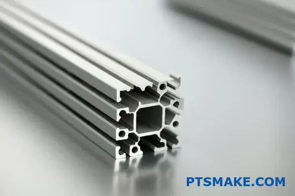
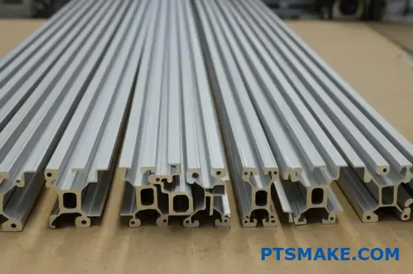
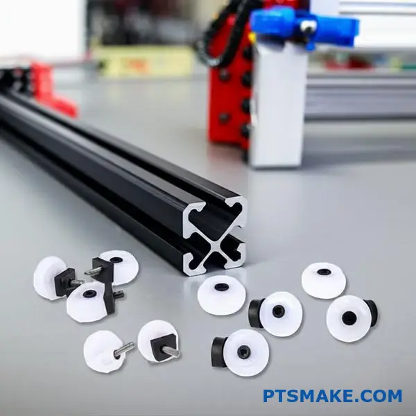
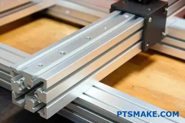
V-Slot profiles feature angled grooves (a ‘V’ shape), specifically designed to accommodate wheels for smooth linear motion. T-Slot profiles have standard rectangular or trapezoidal grooves (a ‘T’ shape), primarily used for building static structural frames, jigs, and machine enclosures with various fasteners.

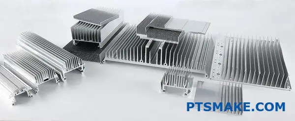
Aluminum extrusions offer a fantastic modular building system, popular in everything from custom machinery to DIY projects. They are created through a process called extrusion1, where aluminum is forced through a die with a specific cross-sectional profile. While many variations exist, the two most common types you’ll encounter are V-Slot and T-Slot. At first glance, they might seem similar, both featuring grooves for connecting components. However, their fundamental design differences dictate their ideal applications. Understanding these distinctions is key to selecting the right profile for structural integrity, motion requirements, and overall project success. Let’s break down the specifics.
Understanding V-Slot Profiles
V-Slot is a type of aluminum extrusion profile characterized by its unique V-shaped groove. This design isn’t just aesthetic; it serves a specific mechanical purpose.
Slot Geometry
The defining feature is the 90-degree angled groove along the length of the profile. This "V" shape is precision-engineered to act as a track.
Primary Use Case
V-Slot’s main advantage is its ability to facilitate linear motion. The angled grooves are designed to perfectly mate with V-shaped wheels (like Delrin or polycarbonate V-wheels). This combination allows for smooth, low-friction rolling motion, making V-Slot extremely popular for building:
- 3D printers (especially the motion axes)
- CNC router gantries
- Camera sliders
- Light-duty automation systems
Fastener Compatibility
While standard T-nuts can sometimes fit into V-Slots, the fit might not be optimal due to the angled sides. The system primarily relies on V-wheels for motion components. For structural connections, specialized V-Slot connectors or standard brackets (often used with T-Slots) can be employed, typically using screws and drop-in or slide-in nuts designed for the profile dimensions, though the selection might be less extensive than for T-Slots.
Motion Capability
This is where V-Slot shines. The synergy between the V-groove and V-wheels provides excellent linear motion capabilities directly integrated into the structural profile itself, reducing the need for separate linear rails in many light-to-medium duty applications.
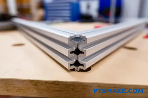
Understanding T-Slot Profiles
T-Slot profiles are arguably the more traditional and widely recognized type of modular aluminum extrusion. They form the backbone of countless industrial frameworks.
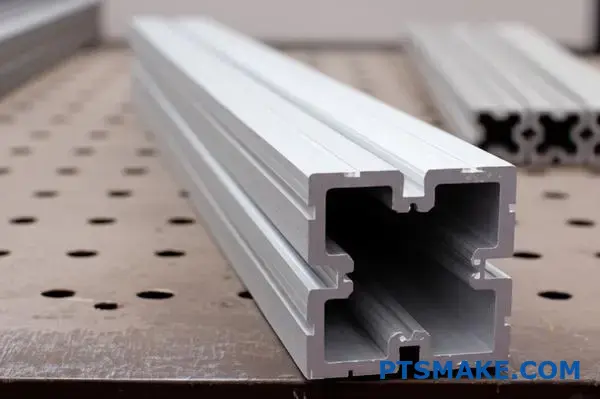
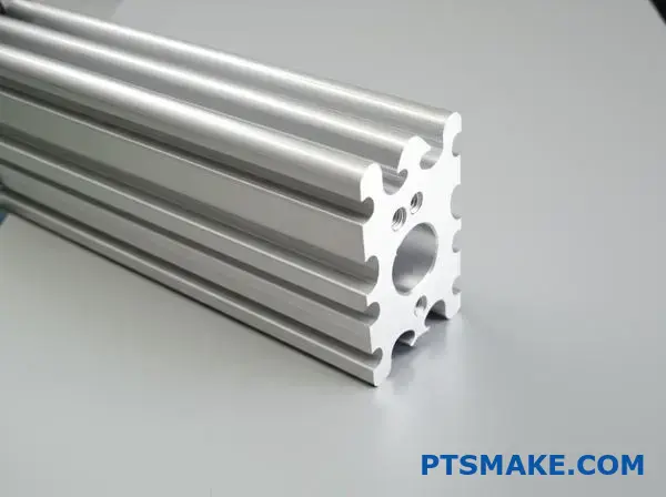
Slot Geometry
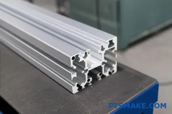
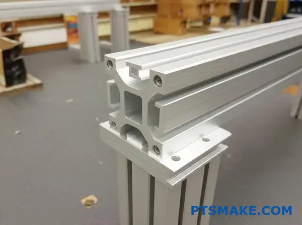
T-Slot profiles feature a groove shaped like a "T" when viewed in cross-section. This shape can vary slightly (some are more trapezoidal), but the core function remains the same: to capture the head of a bolt or a specialized nut (T-nut).
Primary Use Case
The primary function of a t slot aluminum profile is structural. The T-shaped groove provides a versatile and robust method for connecting profiles to each other and attaching various components like panels, sensors, brackets, and feet. Common applications include:
- Machine frames and guarding
- Workbenches and workstations
- Material handling racks and carts
- Test fixtures and jigs
- Prototyping structures
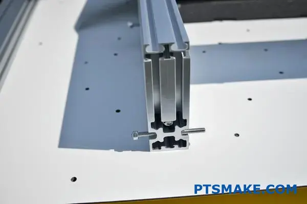
Fastener Compatibility
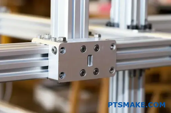
T-Slots boast an extensive ecosystem of compatible fasteners. T-nuts (standard, roll-in, drop-in), T-bolts, and a huge array of specialized connectors and brackets are readily available. This makes building complex, rigid structures relatively straightforward.
Motion Capability
Standard T-Slot profiles are not inherently designed for smooth rolling motion like V-Slots. While you can attach linear bearings or rail systems to T-Slot profiles, the slot itself doesn’t act as the primary motion guide. Its function is connection and structure.
Key Differences Summarized
Here’s a quick comparison table highlighting the core distinctions:
| Funkcia | V-Slot Profile | T-Slot Profile |
|---|---|---|
| Slot Shape | Angled V-Groove (typically 90°) | Rectangular/Trapezoidal T-Groove |
| Primárny účel | Lineárny pohyb | Structural Framing |
| Motion | Integrated (with V-wheels) | Requires added linear motion components |
| Spojovací materiál | V-wheels, Some T-nuts, Brackets | Wide variety of T-nuts, Bolts, Brackets |
| Ecosystem | Growing, focused on motion | Very mature, vast accessory range |
| Typické použitie | 3D Printers, CNC, Camera Sliders | Machine Bases, Guards, Workbenches |

Choosing the Right Profile: Application Matters Most
The decision between V-Slot and T-Slot boils down almost entirely to your application’s requirements.
- Need integrated linear motion? If your design requires components to roll smoothly along the profile itself, V-Slot is generally the better, often more cost-effective choice for light-to-medium loads.
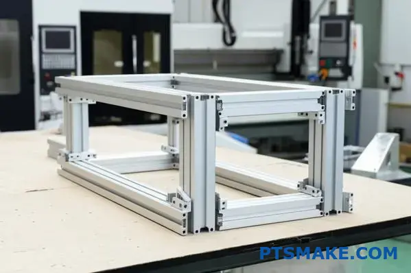
- Need a strong, rigid frame? If you’re building a machine base, enclosure, workbench, or any structure where rigidity and connection strength are paramount, T-Slot is typically the go-to. The wider variety of robust connectors and profile sizes (including heavy-duty options) makes it ideal for structural tasks. In past projects at PTSMAKE, when building robust assembly jigs or CNC machine enclosures, we’ve consistently relied on various series of t slot aluminum profile systems for their proven strength and modularity.
- What about hybrid builds? Yes, you can mix and match! It’s common to see T-Slot used for the main frame of a machine (like a CNC router base) and V-Slot used for the moving gantry that rides upon it.
While V-Slot can be used for structural purposes and T-nuts can sometimes fit in V-Slots, playing to each profile type’s strengths usually results in a better-performing, easier-to-assemble, and more reliable final product. Consider the primary function – motion or structure – and choose accordingly.
Is T-Slot or V-Slot Better for Industrial Applications?
Stuck choosing between T-Slot and V-Slot profiles for that critical industrial build? Are you concerned that picking the wrong system might compromise the machine’s stability or functionality down the line?
For most industrial applications focused on building strong, rigid frames, machine bases, or workstations, T-Slot profiles are generally the better choice due to their wider range of heavy-duty options and connection hardware. V-Slot excels primarily where integrated linear motion is a core requirement.

When we talk about aluminum extrusions, T-Slot and V-Slot are two dominant players, especially in industrial settings, automation, and even complex hobbyist projects. Both offer modularity and flexibility, but their core design differences make them suitable for distinct tasks. Choosing correctly is crucial for performance, longevity, and ease of assembly. Let’s dive deeper than just the slot shape to understand the practical implications for your industrial projects.
Decoding the V-Slot Profile
V-Slot aluminum extrusion is easily identified by its characteristic V-shaped groove running along its length. This specific geometry is key to its primary function.
The Defining ‘V’ Groove
The groove typically features a 90-degree angle. This precise shape isn’t just for looks; it’s engineered to serve as a track for compatible wheels.
Primary Application: Linear Motion
The main strength of V-Slot lies in enabling smooth linear movement. The V-grooves are designed to mate perfectly with V-wheels (often made from materials like Delrin or polycarbonate). This allows components to roll along the extrusion with low friction. This makes V-Slot a popular choice for:
- 3D Printer motion systems (X, Y, Z axes)
- CNC Router gantries (especially lighter-duty machines)
- Camera sliders and dollies
- Custom automation requiring guided movement
Connection Methods
While V-Slot is optimized for motion using V-wheels, you can still make structural connections. Standard T-nuts might fit, but the angled slot walls can sometimes make seating less secure than in a T-Slot. Specialized connectors exist, and standard corner brackets can be used with appropriate screws and nuts (often T-nuts or specialized V-Slot nuts). However, the variety of structural fasteners is generally less extensive compared to the T-Slot ecosystem.
Motion Integration
This is the standout feature. V-Slot integrates the linear guide directly into the structural profile, potentially simplifying designs and reducing costs for applications where high-precision, heavy-load linear rails aren’t necessary.
Understanding the T-Slot Profile
T-Slot aluminum profiles are the workhorse for industrial framing and structures. Their design prioritizes strength and versatile connections.
The Classic ‘T’ Groove
The slot’s cross-section resembles a ‘T’, sometimes with slightly angled sides leading into the main channel (making it somewhat trapezoidal). This shape is designed to capture and secure the head of a T-bolt or, more commonly, a T-nut.
Primary Application: Structural Frameworks
The main purpose of a t slot aluminum profile is to build robust structures. The T-shaped groove provides a secure and highly adaptable method for connecting profiles and attaching countless accessories – panels, sensors, mounting plates, feet, actuators, and more. Common industrial uses include:
- Machine bases and enclosures
- Safety guarding around machinery
- Assembly workstations and ergonomic benches
- Material handling carts and flow racks
- Test fixtures and inspection jigs
At PTSMAKE, we frequently utilize various series of t slot aluminum profiles when constructing durable test rigs or custom machine frames for our clients’ manufacturing needs, valuing their strength and modularity.
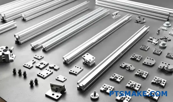
Expansive Fastener Ecosystem
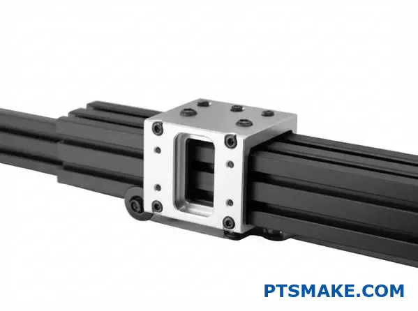
A major advantage of T-Slot is the huge variety of available fasteners and accessories. This includes numerous types of T-nuts (slide-in, roll-in, drop-in, spring-loaded), T-bolts, corner brackets (internal and external), gussets, joining plates, hinges, handles, and mounting hardware. This extensive ecosystem makes complex assemblies more manageable and allows for very strong connections.
Motion Considerations
Standard T-Slot profiles are not designed for integrated rolling motion like V-Slots. While linear motion components (like linear rails and bearing blocks) are often mounted onto T-Slot frames, the slot itself doesn’t serve as the direct pathway for wheels. Its role is primarily connection and support.
Comparing T-Slot vs. V-Slot Head-to-Head
This table summarizes the key differences relevant to industrial applications:
| Funkcia | V-Slot Profile | T-Slot Profile |
|---|---|---|
| Slot Geometry | Angled V-Groove | T-Shaped/Trapezoidal Groove |
| Primárna funkcia | Integrated Linear Motion | Structural Framing & Connection |
| Motion Capability | Built-in (with V-Wheels) | Requires separate linear components |
| Strength Focus | Good for light/medium motion systems | Excellent for structural loads |
| Fastener Variety | More limited, motion-focused | Extremely broad, structure-focused |
| Industrial Focus | Automation, Robotics, 3D Printing | Machine Building, Guarding, Workstations |
| Heavy-Duty Option | Less common | Widely available (e.g., 40, 45 series+) |
Making the Right Choice for Your Industrial Need
Ultimately, the "better" profile depends entirely on the specific demands of your industrial application.
- Prioritizing Structure and Strength? If you’re building a machine base that needs to support heavy equipment, a rigid frame for an assembly line, or robust safety guarding, T-Slot is almost always the superior choice. Its design is optimized for strong connections, and the availability of larger, heavy-duty profiles and a vast array of structural connectors provides greater structural integrity2 and load-bearing capacity. Based on our testing, standard T-Slot connections generally offer higher resistance to torsion and bending forces compared to typical V-Slot structural connections.
- Prioritizing Integrated Linear Motion? If your application requires components to glide smoothly along the extrusion itself, such as in a custom pick-and-place system, a light-duty gantry, or automated testing equipment, V-Slot offers a streamlined solution. It combines structure and motion guidance in one profile.
- Considering a Hybrid Approach? It’s perfectly feasible and often practical to use both. For instance, build the main, static frame of a machine using robust T-Slot profiles and then use V-Slot extrusions for the moving axes or gantries that operate within that frame. Be mindful, however, that directly connecting V-Slot profiles to T-Slot profiles might require specific adapter plates or careful fastener selection due to the different groove geometries and standard T-nut seating.
While you can press V-Slot into service for purely structural roles or jury-rig motion onto T-Slots, aligning your choice with the primary intended function of each profile type generally leads to a more efficient design, easier assembly, and better long-term performance in demanding industrial environments.
What Are T-Slot Rails Used for in Precision Manufacturing?
Ever struggled to build a sturdy, perfectly aligned jig for a complex part? Or needed a custom machine frame that allowed for precise adjustments without the hassle of welding and remachining?
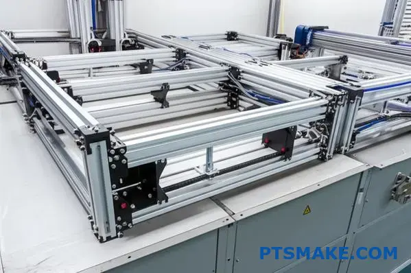
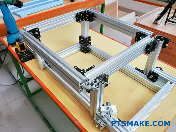
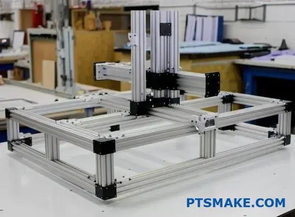
In precision manufacturing, T-slot rails are primarily used for building highly adaptable and rigid frameworks. This includes custom machine bases, assembly jigs, test fixtures, robotic cell enclosures, and guarding systems that require precise component mounting and easy reconfiguration.
T-slot aluminum extrusions, often referred to as rails or profiles, are incredibly versatile. Their unique groove design allows for connections anywhere along the length without drilling or welding. This modularity is a significant advantage, but in precision manufacturing, it’s their ability to create stable, accurate, and adaptable structures that truly makes them indispensable. Based on my 15+ years in precision manufacturing at PTSMAKE, I’ve seen these profiles solve countless challenges where flexibility and accuracy are paramount. Let’s break down exactly how they are applied in these demanding environments.
The Foundation: Why T-Slots Excel in Precision Settings
Before diving into specific uses, it’s important to understand the characteristics that make T-slots suitable for precision work:
- Modularity and Adjustability: Components can be easily added, removed, or repositioned. This is crucial during prototyping, setup adjustments, or when modifying a process. Unlike welded structures, changes don’t require cutting and re-welding, preserving alignment.
- Inherent Straightness and Consistency: Reputable manufacturers produce T-slot extrusions with tight tolerances on straightness and dimensional accuracy. This provides a reliable baseline for building precise assemblies.
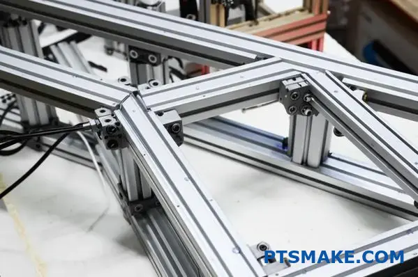
- Strength and Rigidity: When properly sized and connected, T-slot frames can be incredibly strong and resist deflection. This is vital for maintaining accuracy under load, such as in machine bases or measurement fixtures.
- Ease and Speed of Assembly: Building complex frames is significantly faster compared to traditional fabrication methods. This speeds up project timelines, especially for custom, one-off equipment.
Core Applications in Precision Manufacturing
The versatility of T-slot systems lends them to a wide range of applications where accuracy is key.
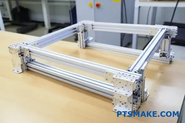
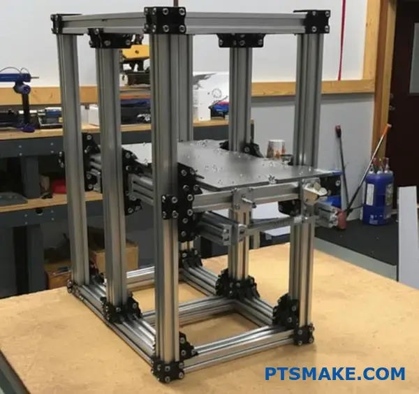
Custom Machine Building
Precision machinery, like specialized CNC equipment, laser cutters, or automated assembly stations, requires a stable and accurate base. T-slot profiles are frequently used to construct the main frame or chassis. Their ability to maintain alignment and resist vibration is critical for the machine’s overall performance and the quality of the parts it produces. We’ve often helped clients at PTSMAKE design bases using heavy-duty t slot aluminum profile systems to ensure maximum rigidity for sensitive processes.
Jigs and Fixtures
This is perhaps one of the most common precision uses. Jigs and fixtures hold workpieces in a specific, repeatable location for machining, assembly, inspection, or testing.
- Machining Fixtures: Securely holding a part while it’s being milled, turned, or ground, ensuring features are created in the correct locations relative to each other.
- Assembly Jigs: Guiding the placement of components during assembly to ensure proper fit and function.
- Inspection Fixtures: Holding a part consistently for measurement by CMMs (Coordinate Measuring Machines) or vision systems. The fixture’s accuracy directly impacts measurement reliability.
The adjustability of T-slots allows fixtures to be easily modified for different part variations or fine-tuned for optimal positioning, ensuring high Opakovateľnosť3.
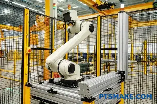
Automated Systems and Robotics
Robotic cells and automated manufacturing lines rely heavily on precisely positioned equipment. T-slots are used to build:
- Robot Pedestals and Mounts: Providing a stable, adjustable platform for mounting industrial robots.
- Safety Enclosures: Creating robust guarding around automated cells that can easily integrate sensors, interlocks, and access panels.
- Conveyor Frameworks: Building the support structures for conveyor systems, ensuring smooth and accurate part transfer.
- Sensor and Camera Mounts: Allowing precise and secure positioning of vision systems, sensors, and actuators within the cell.
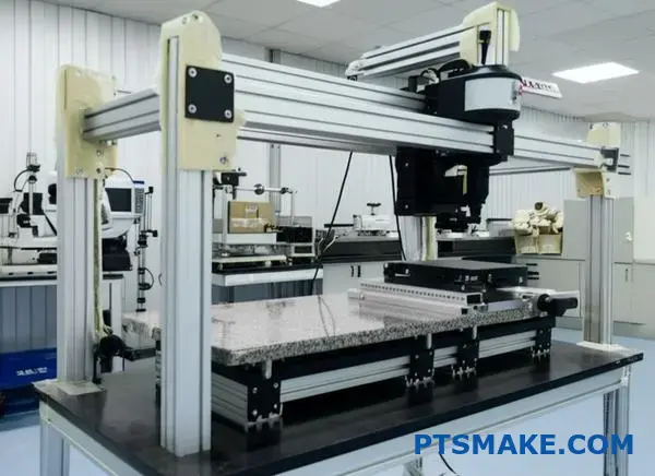
Metrology and Inspection Setups
High-precision measurement demands stable, vibration-resistant platforms. T-slots are ideal for constructing:
- CMM Stands: Supporting heavy granite CMMs or building custom frames for larger measurement volumes.
- Optical Comparator Bases: Creating rigid stands for sensitive optical measurement equipment.
- Custom Measurement Rigs: Building frameworks to hold parts and measurement devices for specific, non-contact inspection tasks.
Why T-Slots Often Win Over Alternatives
While other methods exist, T-slots offer distinct advantages in many precision scenarios:
| Funkcia | T-Slot Framework | Welded Steel Frame | Machined Monolithic Block |
|---|---|---|---|
| Nastaviteľnosť | Vynikajúce | Poor (requires cutting) | Žiadne |
| Čas realizácie | Rýchle | Moderate to Slow | Pomalé |
| Presnosť | Good to Excellent (depends on assembly) | Good (requires post-weld machining) | Vynikajúce |
| Hmotnosť | Light to Moderate | Ťažké | Very Heavy |
| Úprava | Easy | Ťažké | Impossible |
| Cost (Initial) | Mierne | Nízka až stredne vysoká | Veľmi vysoká |
Welded frames can be very rigid but lack adjustability and often require stress relieving and machining after welding to achieve high precision. Monolithic structures offer the ultimate precision but are extremely expensive and inflexible. T-slots strike a balance, offering good precision potential with unparalleled flexibility and faster deployment.
Considerations for Precision T-Slot Use
To maximize accuracy with T-slot systems:
- Choose the Right Profile: Heavier series (like 40×40, 45×45, or larger) generally offer greater rigidity. Consider profiles with more material and thicker walls for critical structures.
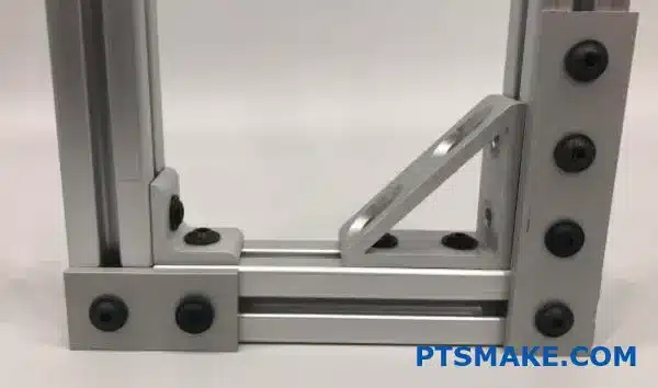
- Use High-Quality Connectors: Opt for robust connection methods like gusseted brackets, joining plates, and properly torqued fasteners. Avoid relying solely on simple corner brackets for high-load or high-precision joints.
- Ensure Proper Assembly: Clean cuts, square assembly, and consistent fastener torque are crucial. In our experience collaborating with clients, careful assembly practices are as important as the components themselves.
- Integrate Linear Motion: While T-slots provide the frame, high-precision linear motion often requires dedicated linear guides and bearings mounted onto the T-slot structure.
In essence, T-slot rails provide the structural backbone for countless precision manufacturing applications, enabling the accuracy, adaptability, and efficiency required in modern industry. Their smart design makes complex setups achievable with relative ease.
How Much Weight Can T-Slot Aluminum Hold in Structural Designs?
Designing a structure and wondering if that t-slot aluminum profile can actually support the load you need? Are you worried about potential bending, failure, or simply overspending on unnecessarily heavy profiles?
The weight capacity of T-slot aluminum isn’t a single number; it depends heavily on the specific profile series (size and geometry), the length of the unsupported span, the type of load applied, and how the structure is connected. Generally, larger profiles with thicker walls handle significantly more weight.

Determining the exact load capacity for your T-slot aluminum structure is crucial for safety and functionality. It’s not as simple as picking a profile and hoping for the best. Several critical factors interact to define how much weight a given extrusion can reliably support. Overlooking any of these can lead to designs that are either dangerously weak or inefficiently overbuilt. In my 15+ years helping engineers and designers at PTSMAKE bring their projects to life, accurately assessing load capacity has always been a fundamental step. Let’s break down the key elements you need to consider.
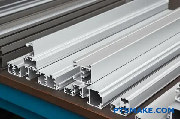
Factor 1: Profile Size and Series
This is often the most significant factor. T-slot extrusions come in various series, typically defined by their outer dimensions (e.g., 20mm series, 30mm series, 40mm series, 45mm series, or fractional inch equivalents like 10 series (1") or 15 series (1.5")).
- Larger Dimensions: Generally, profiles with larger cross-sectional dimensions (like a 40x80mm vs. a 20x20mm) have a much higher moment of inertia, meaning they resist bending far better.
- Series Standards: Different manufacturers might have slightly different internal geometries even within the same nominal series (e.g., standard vs. light vs. heavy versions), impacting strength. Always refer to the specific manufacturer’s data.
Factor 2: Profile Geometry and Wall Thickness
Beyond the overall size, the internal design matters.
- Wall Thickness: Profiles with thicker walls provide more material to resist stress and bending. "Light" or "Eco" versions often reduce wall thickness to save weight and cost, but this directly reduces load capacity.
- Internal Webbing: Some profiles have more complex internal structures (webbing) that add rigidity without significantly increasing weight.
Factor 3: Material Alloy and Temper
Most T-slot profiles are made from 6061 or 6063 aluminum alloys.
- 6061 Alloy: Often offers slightly higher strength compared to 6063.
- Temper (e.g., T6): The heat treatment (temper) significantly affects the material’s yield strength and ultimate tensile strength. T6 is a common temper providing good strength. Always verify the alloy and temper specified by the manufacturer.
Factor 4: Unsupported Span Length
This is critical. The longer the distance between support points (the span), the less weight an extrusion can hold before it starts to bend significantly or fail. Doubling the span can reduce the load capacity by a factor of four or even more, depending on the loading conditions. Short, well-supported beams are much stronger than long ones.
Factor 5: Load Type and Distribution
How the weight is applied makes a big difference.
- Point Load: A load concentrated at a single point (e.g., a motor mounted mid-span) puts the most stress on the beam.
- Distributed Load: A load spread evenly along the length (e.g., a heavy plate resting on the entire beam) is generally easier for the profile to support compared to an equivalent point load.
- Static Load: A constant, unchanging weight.
- Dynamic Load: Loads that involve movement, vibration, or impact (e.g., moving gantries, robotic arms). These require a higher safety factor as they introduce additional forces.
Factor 6: Connection Method
How profiles are joined together impacts the overall structural integrity.
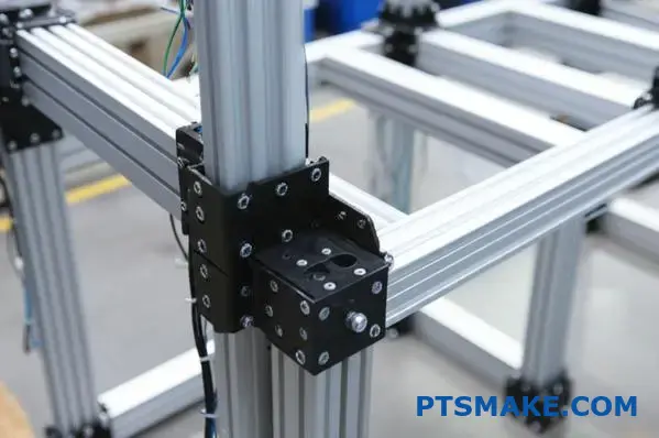
- Robust Connectors: Using strong connectors like gusseted corner brackets, joining plates, and properly torqued fasteners ensures that joints don’t become weak points.
- End Fasteners vs. Brackets: End-tapped fasteners can be convenient but might offer less rigidity against racking forces compared to external brackets in some configurations. At PTSMAKE, for critical structural joints, we often recommend through-bolting or using substantial external connection hardware based on the expected loads discussed with our clients.
Factor 7: Allowable Deflection4
Strength isn’t just about not breaking; it’s also about not bending too much under load. Deflection is the amount a beam bends under load. Even if a profile won’t fail, excessive deflection can cause issues:
- Misalignment of connected parts
- Binding of linear motion components
- Aesthetic concerns or perceived instability
Most manufacturers provide load tables or calculators that specify load capacities based on a maximum allowable deflection (e.g., L/200, meaning the deflection shouldn’t exceed the span length divided by 200). Defining an acceptable deflection limit for your application is crucial.
Putting It All Together: Using Manufacturer Data
Reliable t slot aluminum profile manufacturers provide detailed technical documentation, including:
- Section Properties: Moment of inertia (Ix, Iy), section modulus.
- Load Tables: These tables typically show the maximum allowable point load or distributed load for various span lengths, often based on a specific deflection limit.
Example Load Comparison (Illustrative – Always Use Manufacturer Data):
| Profile Series (Metric) | Relative Stiffness (Approx.) | Typical Use Case Load | Poznámky |
|---|---|---|---|
| 20×20 | Nízka | Light sensors, small guards | Best for very light-duty applications |
| 40×40 (Standard) | Stredné | Workstation frames, light jigs | Common general-purpose profile |
| 40×80 (Standard) | Vysoká | Machine bases, heavier jigs | Good strength in one direction |
| 45×90 (Heavy Duty) | Veľmi vysoká | Heavy machine bases, gantries | Designed for significant loads |
Table data is purely illustrative for comparison.
When in doubt, consult the manufacturer’s specifications or use their provided calculation tools. For complex or critical applications involving dynamic loads or specific safety requirements, performing a proper structural analysis using engineering software (FEA – Finite Element Analysis) or consulting with a structural engineer is highly recommended. Based on our tests and collaborations with clients, using the manufacturer’s load tables with an appropriate safety factor is essential for reliable designs.
How Much Weight Can T-Slot Aluminum Hold in Structural Designs?
Designing a structure and wondering if that specific t-slot aluminum profile can actually support the required load? Are you concerned about potential bending, failure, or simply overspending on unnecessarily heavy profiles?
The weight capacity of T-slot aluminum isn’t a single number; it depends heavily on the specific profile series (size and geometry), the length of the unsupported span, the type of load applied, and how the structure is connected. Generally, larger profiles with thicker walls handle significantly more weight.
Determining the precise load capacity for your T-slot aluminum structure is vital for both safety and functionality. It’s rarely as simple as picking a profile and hoping it holds up. Several critical factors interact to define how much weight a given extrusion can reliably support. Overlooking any of these can lead to designs that are either dangerously weak or inefficiently overbuilt. In working on various projects at PTSMAKE, accurately assessing load capacity has always been a fundamental step in delivering reliable solutions. Let’s break down the key elements you need to consider.
Factor 1: Profile Size and Series
This is often the most significant factor influencing strength. T-slot extrusions come in various series, typically defined by their primary outer dimensions (e.g., metric series like 20mm, 30mm, 40mm, 45mm, or fractional inch equivalents like 1" or 1.5" series).
- Larger Dimensions: As a rule, profiles with larger cross-sectional dimensions (like a 40x80mm compared to a 20x20mm) possess a much higher moment of inertia. This property means they resist bending forces far more effectively.
- Series Standards: Be aware that different manufacturers might offer slightly different internal geometries even within the same nominal series (e.g., standard vs. light vs. heavy versions). These variations directly impact strength. Always refer to the specific manufacturer’s technical data for the profile you intend to use.
Factor 2: Profile Geometry and Wall Thickness
Beyond the overall size, the internal design of the extrusion plays a crucial role.
- Wall Thickness: Profiles featuring thicker walls provide more material to resist stress and bending. Often, "Light" or "Eco" versions are available, which reduce wall thickness to save weight and material cost, but this comes at the direct expense of load-bearing capacity.
- Internal Webbing: Some t slot aluminum profile designs incorporate more complex internal structures, often called webbing. This internal reinforcement adds rigidity and resistance to twisting forces, sometimes without significantly increasing the overall weight compared to a simpler profile of the same outer dimensions.

Factor 3: Material Alloy and Temper
The specific aluminum alloy and its heat treatment (temper) define the base material strength. Most structural T-slot profiles are made from alloys like 6061 or 6063.
- 6061 Alloy: Generally offers slightly higher yield and tensile strength compared to 6063, making it common for more demanding structural applications.
- 6063 Alloy: Still very capable, often chosen for its excellent extrudability and surface finish, suitable for many standard framing needs.
- Temper (e.g., T6): The temper designation (like -T5 or -T6) indicates the specific heat treatment process applied. T6 is a very common temper for structural profiles, providing a good balance of strength and workability. Always verify the exact alloy and temper specified by the manufacturer, as this dictates the material’s mechanical properties.
Factor 4: Unsupported Span Length
This factor is absolutely critical. The load capacity of a beam decreases dramatically as the distance between its support points (the span) increases. A longer unsupported span allows for much more bending under the same load compared to a shorter span. For instance, doubling the span length can reduce the maximum allowable load by a factor of four or more, depending on how the beam is supported and loaded. Short, well-supported beams are inherently much stronger and stiffer than long ones.
Factor 5: Load Type and Distribution
How the weight is applied to the profile significantly impacts the stresses within the material.
- Point Load: A load concentrated at a single location (e.g., mounting a heavy motor directly in the middle of a beam) typically induces the highest bending stress for a given weight.
- Distributed Load: A load spread evenly along the length of the profile (e.g., a heavy equipment base resting uniformly across the beam) generally results in lower peak stress compared to an equivalent point load.
- Static vs. Dynamic Loads: Static loads are constant and unchanging. Dynamic loads involve movement, vibration, or potential impact (like supporting a moving gantry or robotic arm). Dynamic situations introduce additional forces and fatigue considerations, always requiring a higher safety factor in the design calculations.

Factor 6: Connection Method
The way individual profiles are joined together affects the overall rigidity and load distribution of the assembled structure.
- Robust Connectors: Using strong connection hardware, such as heavy-duty gusseted corner brackets, substantial joining plates, and ensuring fasteners are tightened to the correct torque specification, helps ensure that the joints themselves do not become the weak points in the structure.
- End Fasteners vs. Brackets: Tapping the ends of profiles for direct screw connections can be convenient but may offer less resistance to racking or twisting forces compared to using well-designed external brackets, especially in critical load-bearing joints. In past projects at PTSMAKE, for structures requiring maximum stability, we often recommend connection methods that reinforce the joint externally based on the anticipated load types discussed with our clients.
Factor 7: Allowable Deflection5
Structural integrity isn’t just about preventing outright failure (breaking); it’s also about limiting how much the structure bends or flexes under load. Deflection is the measure of this bending. Even if a profile is strong enough not to break, excessive deflection can cause significant problems in many applications:
- Misalignment of interconnected parts or machinery.
- Binding or excessive wear on linear motion components running along the profile.
- Compromised accuracy in jigs, fixtures, or measurement setups.
- Aesthetic issues or a perception of instability in the structure.
Most reputable manufacturers provide load tables or online calculators that specify load capacities often based on a maximum allowable deflection limit. This limit is frequently expressed as a fraction of the span length (e.g., L/200 means the maximum deflection should not exceed the span length divided by 200). It’s essential to define what level of deflection is acceptable for your specific application before selecting the profile.
Putting It All Together: Using Manufacturer Data
Given the interplay of these factors, the most reliable way to determine the load capacity of a specific t slot aluminum profile in your application is to consult the technical documentation provided by the manufacturer. This data typically includes:
- Section Properties: Key geometric values like Moment of Inertia (Ix, Iy) and Section Modulus, which are used in engineering calculations.
- Load Tables: These are invaluable resources. They usually show the maximum allowable point load or distributed load for various unsupported span lengths, often calculated based on a specific maximum deflection limit (e.g., L/200 or L/300).
Example Load Capacity Comparison (Illustrative Purposes Only – Always Refer to Specific Manufacturer Data)
| Profile Series (Metric Example) | Relative Stiffness Category | Typical Application Load Level | Poznámky |
|---|---|---|---|
| 20×20 | Nízka | Very Light (Sensors, Small Guards) | Limited structural use |
| 40×40 (Standard) | Stredné | Light/Medium (Workstations, Jigs) | Common general-purpose profile |
| 40×80 (Standard) | Vysoká | Medium/High (Machine Bases) | Good strength along the 80mm axis |
| 45×45 (Heavy Duty) | Vysoká | High (Robust Frames, Light Gantries) | Thicker walls than standard |
| 45×90 (Heavy Duty) | Veľmi vysoká | Very High (Heavy Machinery, Gantries) | Designed for significant structural loads |
This table provides a general comparison; actual capacities vary significantly by manufacturer and specific profile geometry.
When selecting a profile, always use the specific load tables and technical data from the manufacturer of the extrusion you plan to purchase. Based on our tests and collaborations with clients, applying an appropriate safety factor (especially for dynamic loads or safety-critical structures) on top of the manufacturer’s published limits is crucial for building reliable and safe designs. For highly complex structures, applications involving significant dynamic forces, or where failure could have severe consequences, performing a formal structural analysis using Finite Element Analysis (FEA) software or consulting with a qualified structural engineer is strongly recommended.
What Makes T-Slot Aluminum Ideal for Custom CNC Machined Components?
Have you ever faced the challenge of integrating unique, custom-designed parts into a rigid framework? Does the thought of costly modifications or inflexible welded structures limit your design possibilities?
T-slot aluminum extrusions are ideal for custom CNC machined components primarily due to their exceptional modularity, allowing easy integration, precise positioning, and rapid reconfiguration of bespoke parts without complex fabrication or welding, significantly speeding up prototyping and assembly.
The true beauty of using a t slot aluminum profile system, especially when dealing with custom CNC machined parts, lies in its inherent flexibility. Unlike traditional construction methods that often lock you into a fixed design early on, T-slots offer a dynamic platform perfect for innovation and adaptation. This adaptability is crucial when you’re developing unique machinery, specialized fixtures, or automated systems where standard off-the-shelf solutions just won’t cut it. Let’s explore why this system pairs so well with custom-designed components.
The Power of Adaptable Frameworks
Think about the typical workflow when integrating custom parts. You design a component, perhaps a unique mounting bracket or a specialized sensor holder, often produced via CNC machining for precision. Now, you need to attach it securely and accurately to a larger structure.
Ease of Assembly and Adjustment
With T-slots, this integration becomes remarkably simple. The continuous slots act as universal mounting points. You can slide T-nuts into the slots and position your custom CNC machined part almost anywhere along the length of the extrusion. Fastening it down is just a matter of tightening screws. Need to adjust the position slightly? Loosen the screws, slide the component, and retighten. This contrasts sharply with welded frames, where repositioning often requires cutting, grinding, and re-welding, introducing potential inaccuracies and significant delays.
Speeding Up Prototyping
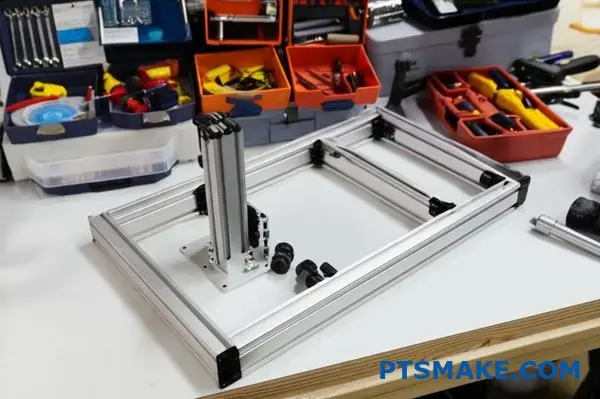
This ease of adjustment is invaluable during prototyping. When testing a new machine design involving custom CNC parts, quick iterations are key. T-slots allow you to rapidly assemble a frame, mount your custom components, test the setup, identify issues, make adjustments, or even swap out redesigned CNC parts with minimal downtime. In past projects at PTSMAKE, this ability to quickly modify T-slot based test rigs saved considerable time and resources compared to building fixed prototypes.
Seamless Integration of Custom CNC Parts
T-slot systems are practically made for incorporating bespoke elements. The standardized slot dimensions provide a predictable interface for your custom designs.
Mounting Custom Brackets and Plates
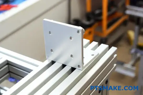
Whether you need a uniquely shaped bracket to hold a motor at an odd angle, a custom plate to mount a specific sensor array, or a complex fixture component, CNC machining can produce these parts with high precision. Designing these parts with simple mounting holes that align with standard T-nut spacing makes attaching them to a T-slot frame straightforward. The frame provides the stable, adjustable backbone, while your CNC part fulfills its specialized function.
Fixtures and Jigs
For manufacturing and assembly, custom jigs and fixtures are often essential. These frequently involve CNC machined components to hold workpieces accurately. Building the base structure from T-slot profiles allows you to easily position and secure these custom elements precisely where needed. The inherent modularity6 of the system means you can build complex, multi-part fixtures that would be difficult or expensive to create using other methods.
Future-Proofing Your Designs
Requirements change. Processes evolve. Equipment gets upgraded. A significant advantage of T-slot framing is its ability to adapt over time.
Modification and Expansion
Imagine needing to add a new sensor, integrate a larger actuator, or modify a workflow. With a T-slot structure supporting your custom CNC components, these changes are relatively easy. You can often add new extrusions, reposition existing components, or swap out custom parts without scrapping the entire frame. This scalability protects your initial investment and allows your equipment to evolve alongside your needs.
Comparison with Welded Structures
| Funkcia | T-Slot Aluminum Frame with CNC Parts | Welded Steel Frame with CNC Parts |
|---|---|---|
| Initial Assembly | Fast, Simple tools | Slower, Requires welding skills |
| Integration | Very Easy (T-nuts, bolts) | Requires drilling/tapping/welding |
| Nastaviteľnosť | Vynikajúce | Very Poor (requires cutting) |
| Úprava | Easy, Reversible | Difficult, Often destructive |
| Reconfigurability | Vysoká | Nízka |
| Lead Time (Mod) | Krátky | Dlhé |
This table highlights the clear advantage of T-slots when flexibility and future adjustments involving custom parts are important considerations.
Kľúčové aspekty návrhu
When designing custom CNC machined components for T-slot integration:
- Standardize Mounting: Design mounting holes in your custom parts compatible with common T-nut sizes and spacings for the profile series you are using.
- Consider Loads: Ensure the chosen T-slot profile and connection methods are robust enough to support the weight and operational forces of your custom components. Heavier CNC parts might necessitate larger profiles or reinforced connections.
- Leverage Both Systems: Use the precision of CNC machining for the critical custom elements and the flexibility of T-slots for the supporting framework and positioning adjustments.
In essence, the combination of precise, custom CNC machined parts and the adaptable framework of a t slot aluminum profile system creates a powerful synergy. It allows engineers and designers like our typical reader, Matthew Shekels, to build sophisticated, tailored solutions quickly and efficiently, without being locked into rigid, hard-to-modify designs. At PTSMAKE, we understand the importance of this integration, providing high-precision CNC machining services that complement the versatility of T-slot construction for industries ranging from robotics to specialized machinery.
What Makes T-Slot Aluminum Ideal for Custom CNC Machined Components?
Ever faced the challenge of integrating unique, custom-designed parts into a rigid framework? Does the thought of costly modifications or inflexible welded structures limit your design possibilities?
T-slot aluminum extrusions are ideal for custom CNC machined components primarily due to their exceptional modularity, allowing easy integration, precise positioning, and rapid reconfiguration of bespoke parts without complex fabrication or welding, significantly speeding up prototyping and assembly.
The true beauty of using a t slot aluminum profile system, especially when dealing with custom CNC machined parts, lies in its inherent flexibility. Unlike traditional construction methods that often lock you into a fixed design early on, T-slots offer a dynamic platform perfect for innovation and adaptation. This adaptability is crucial when you’re developing unique machinery, specialized fixtures, or automated systems where standard off-the-shelf solutions just won’t cut it. Let’s explore why this system pairs so well with custom-designed components.
The Power of Adaptable Frameworks
Think about the typical workflow when integrating custom parts. You design a component, perhaps a unique mounting bracket or a specialized sensor holder, often produced via CNC machining for precision. Now, you need to attach it securely and accurately to a larger structure.
Ease of Assembly and Adjustment
With T-slots, this integration becomes remarkably simple. The continuous slots act as universal mounting points. You can slide T-nuts into the slots and position your custom CNC machined part almost anywhere along the length of the extrusion. Fastening it down is just a matter of tightening screws. Need to adjust the position slightly? Loosen the screws, slide the component, and retighten. This contrasts sharply with welded frames, where repositioning often requires cutting, grinding, and re-welding, introducing potential inaccuracies and significant delays.
Speeding Up Prototyping
This ease of adjustment is invaluable during prototyping. When testing a new machine design involving custom CNC parts, quick iterations are key. T-slots allow you to rapidly assemble a frame, mount your custom components, test the setup, identify issues, make adjustments, or even swap out redesigned CNC parts with minimal downtime. In past projects at PTSMAKE, this ability to quickly modify T-slot based test rigs saved considerable time and resources, such as reducing material waste and manual labor costs, compared to building fixed prototypes.
Seamless Integration of Custom CNC Parts
T-slot systems are practically made for incorporating bespoke elements. The standardized slot dimensions provide a predictable interface for your custom designs.
Mounting Custom Brackets and Plates
Whether you need a uniquely shaped bracket to hold a motor at an odd angle, a custom plate to mount a specific sensor array, or a complex fixture component, CNC machining can produce these parts with high precision. Designing these parts with simple mounting holes that align with standard T-nut spacing makes attaching them to a T-slot frame straightforward. The frame provides the stable, adjustable backbone, while your CNC part fulfills its specialized function.
Fixtures and Jigs
For manufacturing and assembly, custom jigs and fixtures are often essential. These frequently involve CNC machined components to hold workpieces accurately. Building the base structure from T-slot profiles allows you to easily position and secure these custom elements precisely where needed. The inherent modularity7 of the system means you can build complex, multi-part fixtures that would be difficult or expensive to create using other methods.
Future-Proofing Your Designs
Requirements change. Processes evolve. Equipment gets upgraded. A significant advantage of T-slot framing is its ability to adapt over time.
Modification and Expansion
Imagine needing to add a new sensor, integrate a larger actuator, or modify a workflow. With a T-slot structure supporting your custom CNC components, these changes are relatively easy. You can often add new extrusions, reposition existing components, or swap out custom parts without scrapping the entire frame. This scalability protects your initial investment and allows your equipment to evolve alongside your needs.
Comparison with Welded Structures
Here’s a quick look at how T-slots stack up against traditional welded frames when integrating custom CNC parts:
| Funkcia | T-Slot Aluminum Frame with CNC Parts | Welded Steel Frame with CNC Parts |
|---|---|---|
| Initial Assembly | Fast, Simple tools | Slower, Requires welding skills |
| Integration | Very Easy (T-nuts, bolts) | Requires drilling/tapping/welding |
| Nastaviteľnosť | Vynikajúce | Very Poor (requires cutting) |
| Úprava | Easy, Reversible | Difficult, Often destructive |
| Reconfigurability | Vysoká | Nízka |
| Lead Time (Mod) | Krátky | Dlhé |
| Cost (Lifecycle) | Often lower due to adaptability | Can be high due to rework needs |
This table highlights the clear advantage of T-slots when flexibility and future adjustments involving custom parts are important considerations. While initial material costs might sometimes be comparable, the ease of modification with T-slots often leads to lower overall project costs.
Kľúčové aspekty návrhu
When designing custom CNC machined components for T-slot integration:
- Standardize Mounting: Design mounting holes in your custom parts compatible with common T-nut sizes and spacings for the profile series you are using. This simplifies assembly and component swapping.
- Consider Loads: Ensure the chosen T-slot profile and connection methods are robust enough to support the weight and operational forces of your custom components. Heavier CNC parts might necessitate larger profiles or reinforced connections like gussets or joining plates.
- Leverage Both Systems: Use the precision of CNC machining for the critical custom elements where tight tolerances are essential. Use the flexibility of T-slots for the supporting framework, adjustments, and overall structure.
In essence, the combination of precise, custom CNC machined parts and the adaptable framework of a t slot aluminum profile system creates a powerful synergy. It allows engineers and designers like our typical reader, Matthew Shekels, to build sophisticated, tailored solutions quickly and efficiently, without being locked into rigid, hard-to-modify designs. At PTSMAKE, we understand the importance of this integration, providing high-precision CNC machining services that complement the versatility of T-slot construction for industries ranging from robotics and automation to specialized machinery development. We focus on delivering reliable components that fit seamlessly into these flexible systems.
What Makes T-Slot Aluminum Ideal for Custom CNC Machined Components?
Ever struggled to mount a unique, precisely machined part onto a structure, only to find adjustments difficult or impossible? Are you looking for a way to build frameworks that easily accommodate custom components without locking you into a fixed design?
T-slot aluminum extrusions provide an ideal foundation for custom CNC machined components because their inherent modularity allows for easy mounting, precise positioning, simple adjustments, and rapid prototyping, bypassing the rigidity and rework associated with welded frames.
When building specialized machinery, fixtures, or automated systems, standard parts often don’t suffice. You need components machined to exact specifications – parts that perform a unique function or fit a specific space. Integrating these custom CNC machined parts into a larger assembly efficiently and accurately can be a major hurdle. This is where the strengths of a t slot aluminum profile system truly shine, offering a level of flexibility that traditional fabrication methods simply can’t match.
The Power of an Adaptable Foundation
The core advantage lies in the T-slot itself. This continuous groove acts as a universal docking system along the entire length of the extrusion.
Effortless Integration
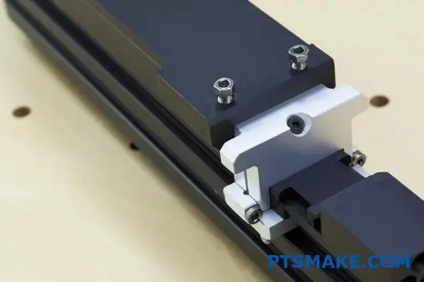
Imagine you’ve just received a custom CNC machined bracket from a supplier like us at PTSMAKE. With a T-slot frame, mounting it is straightforward. You simply slide T-nuts into the slot, position your custom part, and secure it with bolts. There’s no need for precise pre-drilling into a solid frame or the complexities of welding. This simplifies assembly immensely, especially when dealing with multiple custom parts.
Precision Positioning and Adjustment
Need to mount that custom sensor bracket exactly 150mm from the end? Or perhaps testing reveals it needs to be shifted slightly? T-slots make this easy. Loosen the bolts, slide the component along the slot to the precise location (often using measurement marks on the profile or simple jigs), and retighten. This fine-tuning capability is invaluable, ensuring that your custom CNC parts are positioned with the required accuracy for optimal performance. Achieving this level of positional freedom and accuracy with a welded structure would require significant rework.
Simplifying the Design of Custom Components
Knowing you’ll use a T-slot frame can even simplify the design of the custom CNC parts themselves.
Standardized Mounting Features
Instead of designing complex mounting flanges or needing to predict exact hole locations on a large frame, you can design your CNC parts with simple through-holes or counterbores spaced appropriately for standard T-nuts. This makes the custom part itself potentially simpler (and often more cost-effective) to machine, focusing the complexity on its functional aspects rather than its mounting interface.
Versatile Fixturing
This synergy is particularly powerful when creating jigs and fixtures. You can use T-slot profiles to build the main structure, providing overall rigidity and gross positioning. Then, custom CNC machined blocks, clamps, or locators can be precisely mounted onto the T-slots to interface perfectly with the workpiece. This combination allows for highly accurate and adaptable fixtures that can often be reconfigured for different parts or process variations. In our experience at PTSMAKE, building test fixtures this way significantly speeds up development for clients in industries like aerospace and medical devices.
Accelerating Prototyping and Iteration Cycles
Bringing a new product or automated system to life often involves trial and error. T-slot systems dramatically accelerate this iterative process.
Rapid Assembly and Modification
You can assemble a prototype frame, mount your initial custom CNC components, and test functionality in a fraction of the time it would take to fabricate and assemble a welded structure. If testing reveals a need for change – perhaps a custom bracket needs strengthening or a mounting point needs relocation – you can quickly unbolt, swap, or reposition components. This rapid feedback loop allows designers and engineers, like our typical reader Matthew Shekels developing hardware at Nimble Robotics, to refine their designs much faster.
Reduced Waste and Cost
Modifying a T-slot frame rarely requires scrapping major components. Profiles can be reused, and only the specific custom parts needing changes require remanufacturing. This contrasts sharply with welded frames, where modifications often involve cutting and re-welding, potentially compromising the frame’s integrity or requiring a complete rebuild, thus saving material and labor costs.
T-Slot vs. Welded Frames for Custom Integration
Here’s a quick comparison focusing on integrating custom CNC parts:
| Funkcia | T-Slot Aluminum Frame | Welded Steel/Aluminum Frame |
|---|---|---|
| CNC Part Mounting | Easy (T-nuts, bolts) | Requires drilling/tapping/welding |
| Position Adjustment | Excellent, Continuous | Very Difficult, often destructive |
| Prototyping Speed | Rýchle | Pomalé |
| Modification Ease | High, Reversible | Low, Labor-intensive |
| Reconfigurability | Vysoká | Veľmi nízka |
| Potential for Damage | Low (non-destructive assembly) | Moderate (welding heat/distortion) |
This comparison underscores why T-slot systems are favored when flexibility and integration of custom elements are key design drivers. The system maintains good rozmerová stabilita8 during assembly and modification, which is crucial for precision applications.
Choosing a T-slot aluminum framework provides an inherently adaptable and precise platform that perfectly complements the use of custom CNC machined components. It simplifies integration, enables easy adjustments, speeds up development, and allows for future modifications – making it an ideal choice for innovative projects requiring tailored parts and flexible structures.
Learn more about the aluminum extrusion process and its impact on profile properties. ↩
Discover how profile geometry and connection methods directly impact the overall stability and load capacity of your frame. ↩
Learn how T-slot systems help achieve consistent part positioning, critical for quality in automated processes and fixture design. ↩
Understanding deflection helps ensure your structure performs correctly and safely under load, not just avoids breaking. ↩
Understand how deflection limits affect structural performance and component alignment in your designs. ↩
Explore how the inherent modular design simplifies assembly, customization, and future modifications for complex structures. ↩
Explore how the inherent modular design simplifies assembly, customization, and future modifications for complex structures. ↩
Understanding this ensures your framework maintains accuracy over time and under various operational loads. ↩