Understanding Large-Scale Injection Molding Capabilities
Have you ever wondered how those massive plastic components in your car, washing machine, or garden furniture are made so precisely? The technology behind these engineering marvels is more fascinating than most people realize.
Large plastic injection molding services represent a specialized manufacturing capability that transforms industrial production possibilities, enabling the creation of oversized components with remarkable precision while maintaining cost efficiency for high-volume applications.
The Evolution of Large-Scale Injection Molding
Large-scale injection molding has transformed dramatically over my years in the industry. What once required multiple components assembled together can now be produced as single, cohesive units. This evolution hasn’t been merely about size – it’s been about precision, efficiency, and expanding what’s possible in plastic manufacturing.
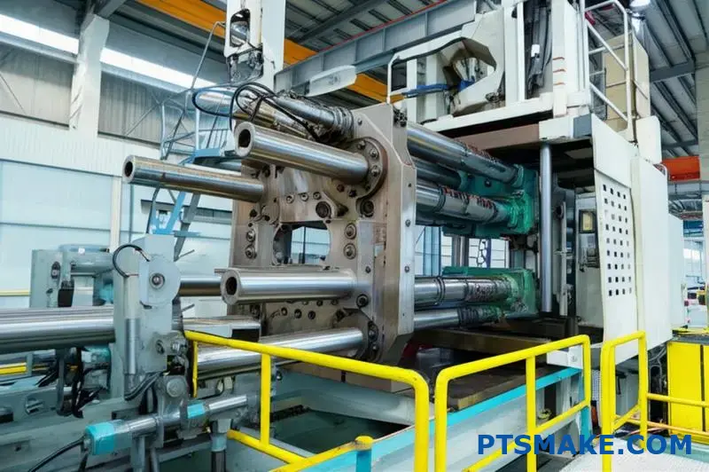
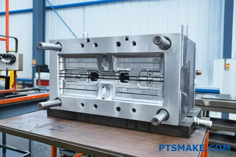
The journey from conventional molding to large-scale capabilities required significant engineering innovations. Modern large plastic injection molding machines operate with clamping forces ranging from 1,000 to 4,400 tons – exponentially greater than standard equipment. This remarkable force is necessary to maintain mold closure against the immense pressure created when injecting material into large cavities.
Technical Specifications of Large-Scale Molding
Size Capabilities
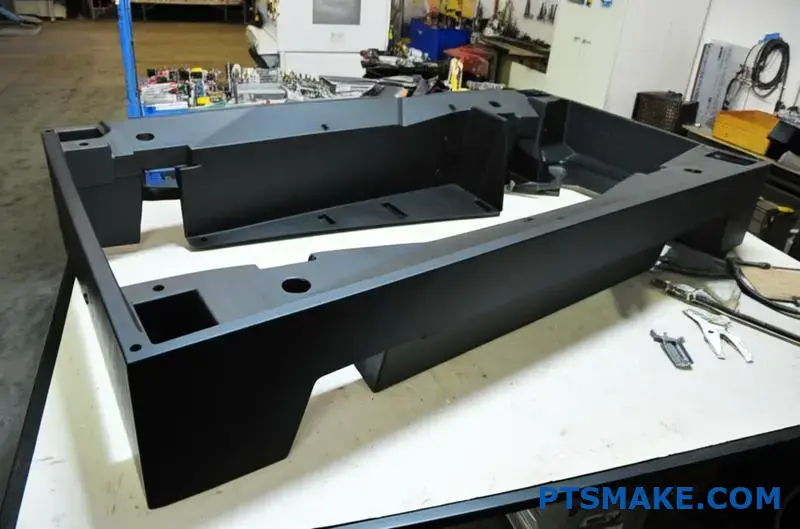
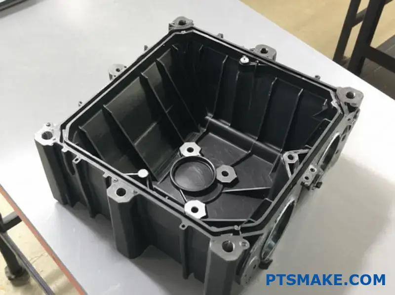
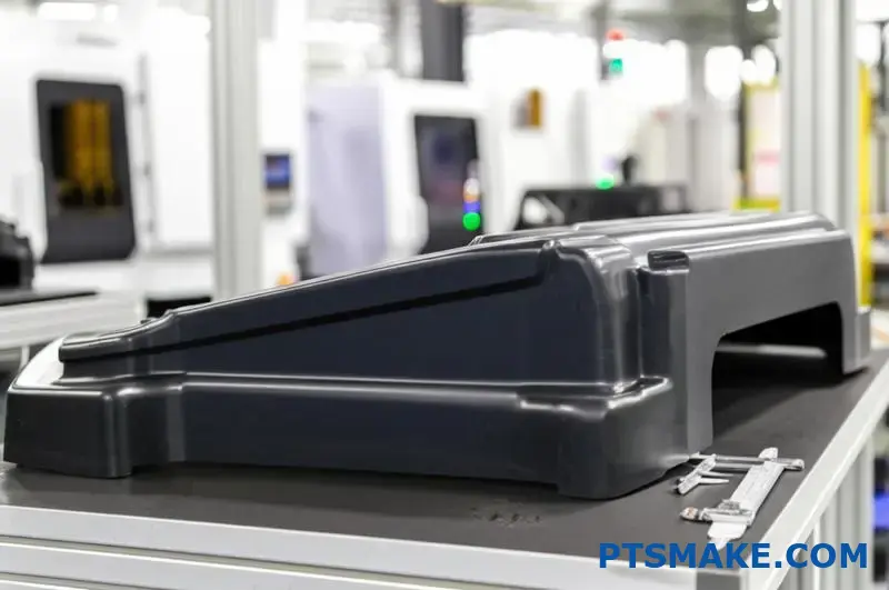
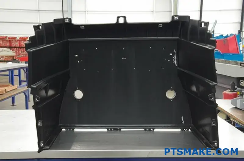
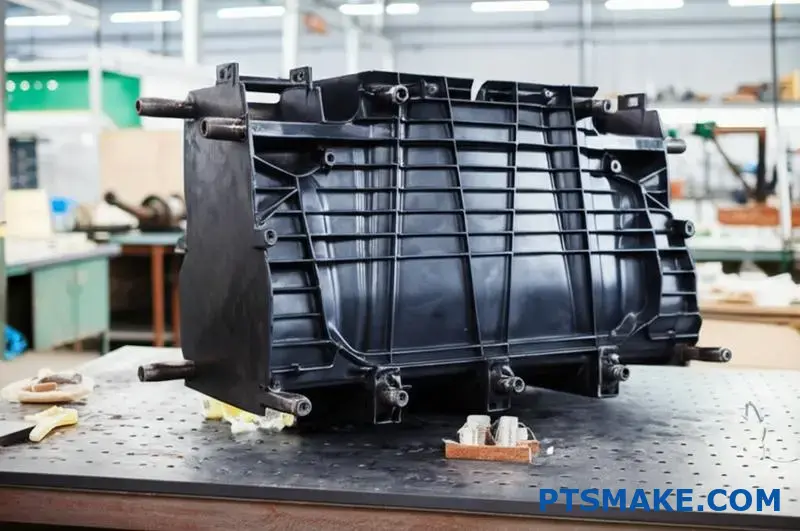
The dimensions achievable through large-scale injection molding are truly impressive. At PTSMAKE, our equipment can produce components up to 60" x 60" x 25" as single pieces. This capability eliminates the need for complex assembly operations and reduces potential failure points in finished products.
Precision and Tolerance Control
Perhaps most remarkable is that these massive components maintain exceptional precision. Despite their size, our large-scale molding processes can achieve tolerances as tight as +/-0.003 inches. This level of accuracy requires sophisticated process monitoring systems1 that continually adjust parameters during production.
Material Options for Large Components
Large-scale molding isn’t limited to basic materials. We routinely process:
- Engineering-grade thermoplastics (PC, ABS, Nylon)
- Glass-filled composites for structural applications
- Impact-modified formulations for durability
- Custom-colored materials for aesthetic consistency
Industry Applications
Automotive Sector
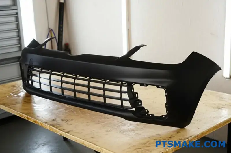
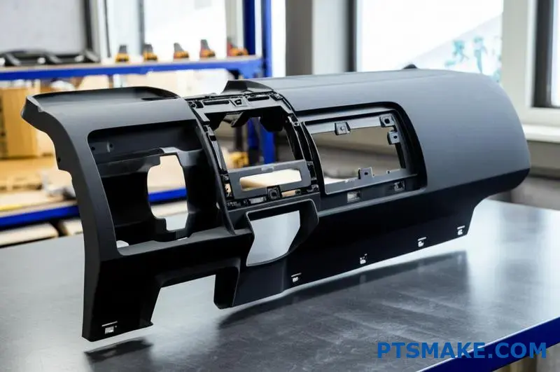
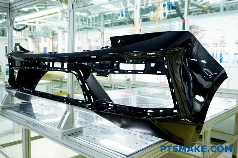
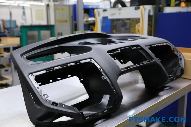
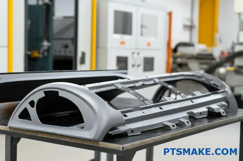
The automotive industry represents one of the primary markets for large plastic injection molding services. Components such as:
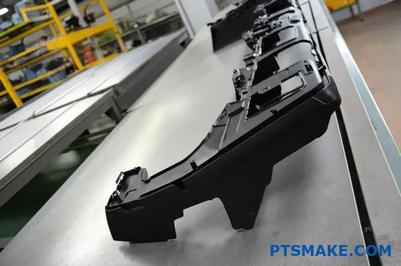
- Instrument panels and dashboards
- Bumper systems
- Interior door panels
- Under-hood components
All benefit from large-scale molding capabilities. These parts often require complex geometries with integral features like mounting brackets, reinforcement ribs, and precision fittings – all produced in a single molding cycle.
Consumer Goods and Appliances
Major appliance manufacturers leverage large-scale molding for:
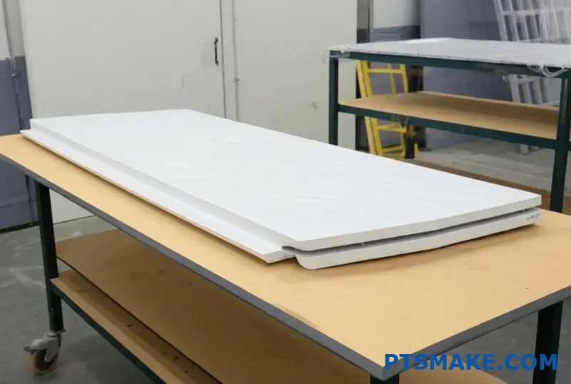
- Washing machine tubs
- Refrigerator liners
- Large appliance housings
- Durable outdoor furniture
These applications benefit from the dimensional stability and structural integrity that properly designed large-scale molded parts provide.
Material Handling Solutions
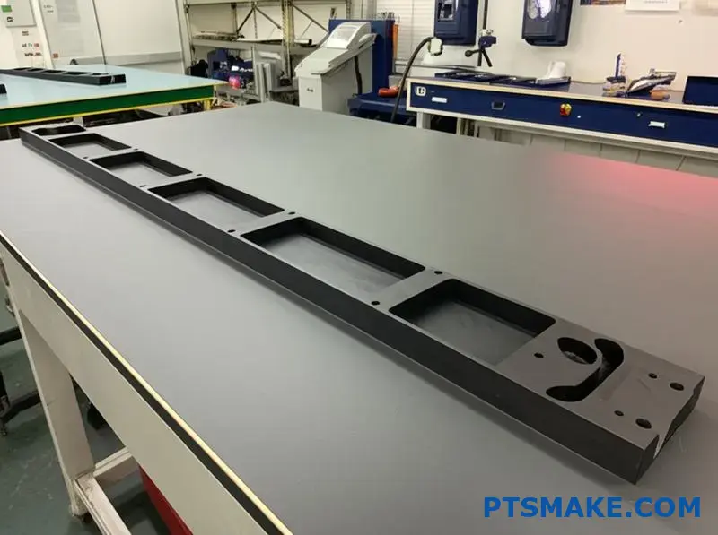
Industrial containers, pallets, and storage systems increasingly utilize large-scale molded components to achieve:
| Benefit | Traditional Assembly | Large-Scale Molding |
|---|---|---|
| Weight Reduction | Limited by joint strength | Optimized through design |
| Durability | Multiple failure points | Unified structure |
| Cost Efficiency | Labor-intensive assembly | Automated production |
| Consistency | Variable quality | Repeatable processes |
Engineering Considerations for Large-Scale Molding
Designing for large-scale injection molding requires specialized expertise. Critical factors include:
Wall Thickness Management
Maintaining consistent wall thickness becomes increasingly challenging as part size increases. Our engineering team carefully analyzes designs to prevent issues like:
- Sink marks in thicker sections
- Warpage from uneven cooling
- Structural weaknesses from thin areas
- Flow-front hesitation causing cosmetic defects
Gate and Runner Systems
The feed system for large molds requires careful engineering. Multiple gates are typically required to ensure complete filling, but their placement must be strategically determined to prevent:
- Visible weld lines in cosmetic areas
- Air entrapment causing voids
- Excessive pressure drops affecting part quality
- Uneven packing and dimensional issues
Cooling System Design
Effective cooling represents perhaps the most critical aspect of large-scale mold design. The thermal management system must extract heat uniformly from these massive parts to prevent warpage and ensure cycle time efficiency. At PTSMAKE, we implement advanced conformal cooling channels that follow the part geometry to optimize this critical process element.
Through properly engineered large-scale injection molding processes, manufacturers can achieve remarkable results that would be impossible through conventional methods, transforming what’s possible in plastic component design and production.
Advanced Tooling Options for Complex Large Parts
Ever wonder why some manufacturers can create massive plastic parts with incredible precision while others struggle? The secret lies not in the machines, but in the sophisticated tooling systems that make large-scale production possible.
High-performance mold tooling represents the critical foundation for successful large plastic injection molding services, with options ranging from rapid prototype tools to production-grade multi-cavity molds engineered specifically for oversized components.
Understanding Mold Classification Systems
When dealing with large plastic components, tooling selection becomes even more critical than with standard-sized parts. The industry classifies molds into several categories based on their construction, longevity, and precision capabilities.
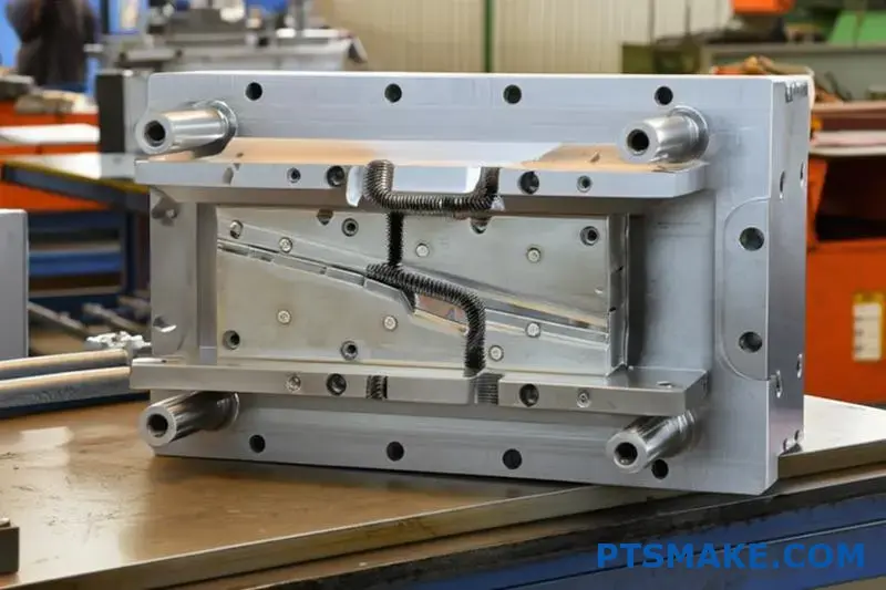
Class 105: Prototype Tooling
Prototype tooling offers the fastest path to initial part validation for large components. These aluminum-based molds provide several advantages:
- Reduced lead time (typically 2-3 weeks versus 8-10 for steel)
- Lower initial investment
- Ability to validate design concepts before committing to production tooling
- Opportunity to produce limited quantities for market testing
However, these tools have limitations when it comes to large parts. The aluminum construction means they can handle fewer cycles before showing wear, especially with the substantial pressures required for large components.
Class 103 and 104: Bridge Tooling
Bridge tooling represents a middle ground between prototype and production molds. These tools utilize steel inserts in critical wear areas while maintaining more economical materials in less stressed regions.
For large plastic injection molding services, bridge tooling offers compelling benefits:
- Extended production capabilities (typically 50,000-100,000 cycles)
- Improved dimensional stability compared to aluminum
- Better heat dissipation for faster cycles
- More economical than full production tooling when volumes are uncertain
At PTSMAKE, we’ve used bridge tooling successfully for clients who need to launch products while their higher-volume production tools are still in development.
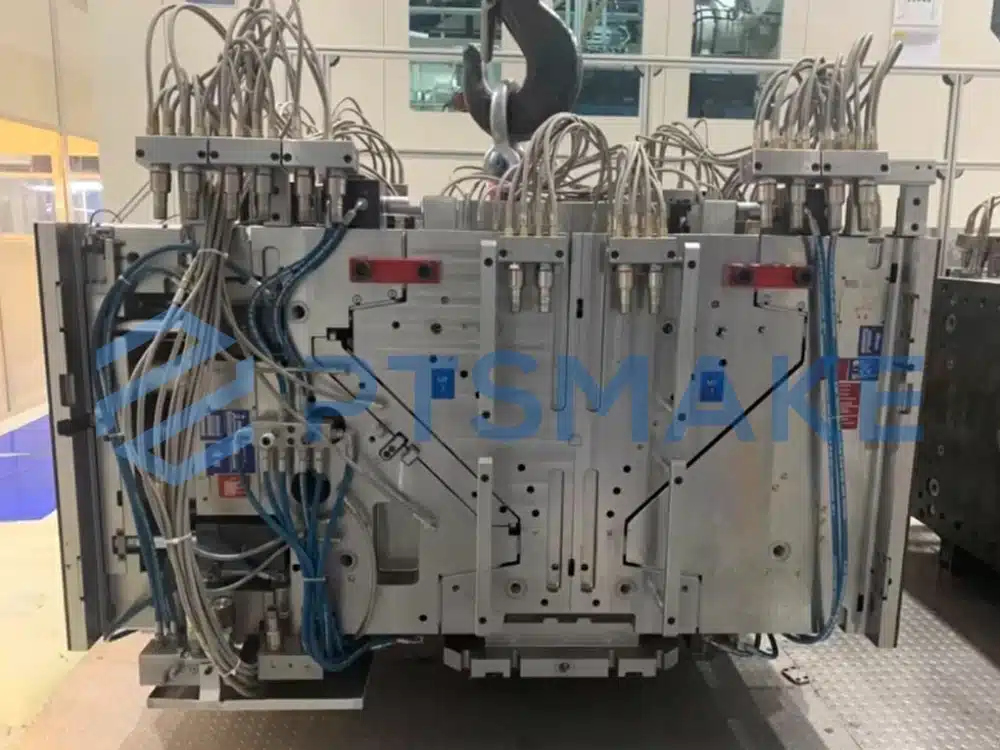
Class 101 and 102: Production Tooling
When dealing with large components in high volumes, Class 101 and 102 production tooling becomes essential. These hardened steel molds offer:
- Virtually unlimited production capacity (millions of cycles)
- Superior dimensional stability throughout the production run
- Ability to withstand high injection pressures required for large parts
- Enhanced cooling capabilities for cycle time optimization
The investment in Class 101 tooling for large components is substantial, but the per-part economics become increasingly favorable as production volumes rise.
Multi-Cavity Configurations for Large Parts
One of the most significant advancements in large plastic injection molding services has been the development of multi-cavity tooling for oversized components. This approach presents unique engineering challenges but delivers compelling benefits.
Single vs. Family vs. Multi-Cavity Options
The tooling configuration options include:
| Configuration Type | Description | Best Application |
|---|---|---|
| Single Cavity | One large part per cycle | Complex geometries with tight tolerances |
| Family Mold | Different related parts in one tool | Products with multiple components needed in equal quantities |
| Multi-Cavity | Multiple identical large parts per cycle | High-volume production where efficiency is paramount |
For large components, the engineering complexities of multi-cavity molds increase exponentially. The mold flow analysis2 required to ensure proper filling of all cavities becomes significantly more sophisticated.
Balancing Complexity with Efficiency
When designing multi-cavity tooling for large components, several factors must be carefully balanced:
- Pressure distribution – Ensuring each cavity receives equal pressure despite the distance from the injection point
- Thermal management – Creating uniform cooling across massive steel structures
- Venting requirements – Properly evacuating air from multiple large cavities
- Ejection systems – Developing robust methods to remove substantial parts without damage
Through proper engineering, multi-cavity tooling can dramatically improve production economics for large parts, often reducing per-part costs by 30-50% compared to single-cavity approaches.
Critical Feature Tolerance Management
Maintaining tight tolerances on large molded parts presents unique challenges that must be addressed through sophisticated tooling approaches.
Steel Selection and Heat Treatment
For large molds where dimensional stability is critical, the selection of appropriate tool steels becomes even more important. We typically recommend:
- P20 pre-hardened steel for general-purpose large molds
- H13 for areas exposed to high wear or abrasive materials
- S7 for components with challenging ejection requirements
- 420 stainless steel for corrosion-resistant applications or medical parts
The heat treatment process must be carefully controlled to prevent warpage in these massive steel structures, often requiring specialized heat treatment facilities.
Insert Strategy for Complex Features
One of the most effective approaches for maintaining tight tolerances on critical features is the strategic use of inserts within the larger mold structure. This allows:
- Different materials for different portions of the mold
- Separate maintenance schedules for high-wear areas
- Ability to replace only damaged sections rather than entire tools
- Enhanced cooling focused on critical dimensions
At PTSMAKE, we’ve developed sophisticated insert strategies that allow us to hold tolerances as tight as ±0.001" even on parts measuring several feet in dimension.
Cooling System Design for Dimensional Stability
The cooling system design in large molds directly impacts dimensional stability. Traditional straight-drilled cooling channels often prove inadequate for massive parts. Instead, we implement:
- Conformal cooling channels that follow part geometry
- Thermal pins for areas inaccessible to conventional cooling
- Segregated cooling zones with independent temperature control
- Advanced thermal monitoring during production
Through these sophisticated approaches to tooling design, manufacturers can achieve remarkable precision even with the most challenging large-scale plastic components.
Material Selection for Large Plastic Components
Ever wondered why some large plastic products crack under pressure while others last for years? The secret lies not in manufacturing techniques but in the critical material selection process that happens long before production begins.
Selecting the right material for large plastic components involves balancing structural integrity, weight considerations, and cost efficiency while ensuring the chosen polymer can withstand the stresses unique to oversized applications.
Understanding Material Requirements for Large-Scale Applications
When it comes to large plastic components, not all materials are created equal. The demands placed on oversized parts differ significantly from their smaller counterparts. At PTSMAKE, I’ve seen numerous projects fall short because material selection wasn’t given the attention it deserved.
Key Performance Considerations
Large plastic components face unique challenges that directly influence material selection:
- Higher structural loads and potential for deflection
- Increased susceptibility to warpage during cooling
- Greater exposure to environmental factors
- More significant impact from material shrinkage
- Enhanced requirements for dimensional stability
These factors create a complex decision matrix that requires deep material knowledge to navigate successfully.
Engineering Plastics for Structural Applications
For components where structural integrity is paramount, engineering plastics offer superior performance characteristics compared to commodity resins.
Glass-Filled Nylon Compounds
Glass-filled nylon (PA) represents one of the most versatile material options for large components. The glass fiber reinforcement significantly improves:
- Tensile strength (up to 3x stronger than unfilled nylon)
- Heat deflection temperature
- Dimensional stability during environmental changes
- Creep resistance under sustained loads
These properties make glass-filled nylon ideal for large automotive components, industrial housings, and structural frames. We typically recommend 30-33% glass loading as the optimal balance between strength and processability for most large applications.
Polycarbonate and PC/ABS Blends
Polycarbonate (PC) and its blends with ABS deliver an exceptional combination of impact resistance and dimensional stability essential for large components. Key benefits include:
| Property | Polycarbonate | PC/ABS Blend |
|---|---|---|
| Impact Strength | Excellent | Very Good |
| Temperature Resistance | Up to 135°C | Up to 110°C |
| UV Stability | Poor (needs additives) | Moderate |
| Processing Ease | Moderate | Excellent |
| Relative Cost | Higher | Moderate |
When designing large exterior panels or housings that require both structural integrity and aesthetic appeal, PC/ABS blends often provide the ideal balance of properties and processability.
High-Performance Resins for Demanding Applications
Some large components face extreme conditions that require specialized high-performance materials.
PEEK and PEI for Critical Applications
For the most demanding large-scale applications, polyetheretherketone (PEEK) and polyetherimide (PEI) offer exceptional performance:
- Operating temperatures exceeding 200°C
- Superior chemical resistance against aggressive substances
- Excellent mechanical properties even at elevated temperatures
- Inherent flame retardancy (particularly PEI)
These materials come at a premium price point but deliver unmatched performance for large components in aerospace, medical, and specialized industrial applications. At PTSMAKE, we’ve successfully molded PEEK components up to 36 inches in length while maintaining tight tolerances despite the material’s challenging processing characteristics.
Advanced Composite Formulations
Recent advances in material science have produced specialized composite formulations specifically engineered for large components:
- Carbon fiber reinforced polymers for maximum strength-to-weight ratio
- Long glass fiber thermoplastics (LFT) for improved impact properties
- Hybrid reinforcement systems3 that combine multiple fiber types
- Specialty additives for enhanced mold flow in massive parts
These advanced formulations help overcome many traditional limitations associated with large part molding, enabling designs that were previously impossible to produce.
Material Selection Process for Large Components
Selecting the optimal material for large plastic components requires a systematic approach that considers both technical requirements and manufacturing constraints.
Technical Parameter Assessment
The selection process begins with a comprehensive assessment of technical parameters:
- Mechanical requirements: Identify specific strength, stiffness, and impact resistance needs
- Environmental exposure: Evaluate UV exposure, chemical contact, and temperature ranges
- Regulatory compliance: Determine relevant standards for the application (UL, FDA, ISO, etc.)
- Expected service life: Define the required durability timeframe
- Dimensional stability needs: Assess tolerance requirements across environmental conditions
These parameters create a profile that narrows potential material candidates before considering manufacturing factors.
Manufacturing Considerations
For large components, material selection must account for manufacturing feasibility:
- Flow characteristics: Materials must maintain consistent flow over long distances
- Cycle time impact: Some materials require significantly longer cooling phases
- Equipment compatibility: High-temperature materials may require specialized equipment
- Post-molding stability: Some materials continue to shrink or warp days after molding
- Secondary operations: Material selection affects painting, welding, and assembly processes
When we develop large components at PTSMAKE, we often create material selection matrices that weigh these factors against cost considerations to identify the optimal material choice.
Cost-Benefit Analysis
The final selection typically requires balancing performance requirements against economic factors:
- Initial material cost per kilogram
- Processing efficiency impact on piece price
- Expected rejection rates during production
- Tooling considerations (some materials require specialized steel or coatings)
- Secondary operation requirements and associated costs
By thoroughly analyzing these factors, manufacturers can identify materials that deliver the necessary performance while maintaining economic viability for large-scale production.
Material Selection Case Studies
Through my experience at PTSMAKE, I’ve observed several patterns in successful material selection for large components across different industries:
- Automotive interior panels: Glass-filled polypropylene provides an excellent balance of cost, weight, and structural performance
- Industrial equipment housings: PC/ABS blends offer superior impact resistance and aesthetics with good structural integrity
- Medical equipment enclosures: PEI delivers the necessary flame retardancy, chemical resistance, and durability
- Large consumer goods: Impact-modified acrylic provides exceptional aesthetics with good structural performance
The common thread across successful implementations is a thorough understanding of both application requirements and material capabilities, combined with rigorous testing before full-scale production commitment.
Specialized Techniques for Large Part Manufacturing
Ever wondered how manufacturers create those enormous plastic components for vehicles, appliances, or industrial equipment with such remarkable precision? The secret lies in specialized molding techniques that transform the impossible into reality through innovative engineering approaches.
Advanced molding technologies have revolutionized large plastic injection molding services by introducing specialized processes like gas-assist, structural foam, and stack mold techniques that maximize efficiency while maintaining exceptional structural integrity and dimensional stability.
Gas-Assist Injection Molding: Creating Hollow Sections in Massive Parts
Gas-assist injection molding represents one of the most significant breakthroughs for manufacturing large plastic components. This innovative process involves injecting nitrogen gas into partially filled mold cavities, creating controlled hollow sections within thick-walled parts.
The Gas-Assist Process Explained
The gas-assist process follows a specific sequence:
- Initial injection of molten plastic material (typically 70-80% of the total cavity volume)
- Precise introduction of nitrogen gas under controlled pressure
- Gas follows the path of least resistance through thicker sections
- Formation of hollow channels while maintaining solid outer surfaces
- Gas pressure holds material against mold walls during cooling
- Gas venting before part ejection
This approach delivers remarkable benefits for large components. By creating controlled hollow sections, we can produce parts with significantly reduced material usage while maintaining excellent structural rigidity. The internal gas channels effectively function as "invisible ribbing" that supports the part structure.
Advantages for Large Component Manufacturing
The benefits of gas-assist technology for large plastic injection molding services include:
| Benefit | Technical Impact | Business Value |
|---|---|---|
| Material Reduction | 20-40% less plastic used | Lower raw material costs |
| Weight Reduction | Lighter components with equivalent strength | Improved product efficiency |
| Reduced Cycle Time | Faster cooling due to thinner overall walls | Increased production capacity |
| Minimized Sink Marks | Gas pressure eliminates surface depressions | Enhanced aesthetic quality |
| Less Warpage | More uniform cooling characteristics | Improved dimensional stability |
At PTSMAKE, we’ve successfully implemented gas-assist technology for components like large automotive instrument panels, where the technique creates internal reinforcement channels that would be impossible with traditional molding approaches.
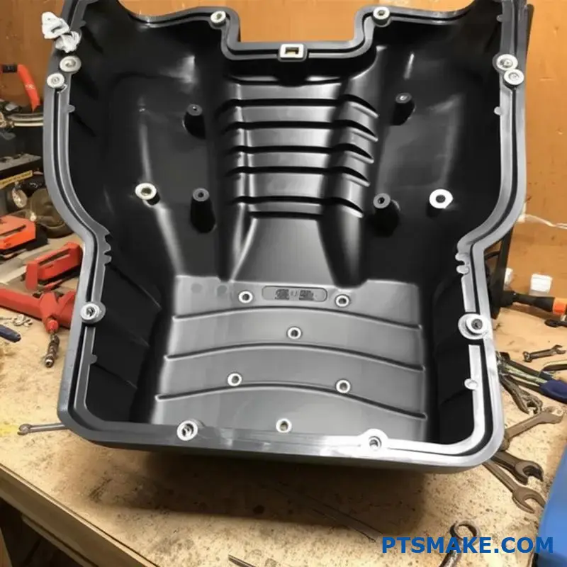
Structural Foam Molding: Engineering Lightweight Strength
Structural foam molding represents another specialized technique particularly valuable for large-scale components requiring exceptional strength-to-weight ratios.
Process Mechanics and Chemistry
The structural foam process utilizes a chemical blowing agent (CBA) mixed with the polymer resin before injection. When the material enters the mold, the blowing agent creates a cellular core structure while maintaining a solid outer skin. The result is a sandwich-like construction with remarkable structural properties.
The foam core typically represents 20-35% of the total part thickness, creating a lightweight cellular structure surrounded by a dense, solid surface layer. This structure mimics engineering principles found in I-beam construction, where material is strategically placed to maximize structural integrity.
Engineering Benefits for Oversized Components
Structural foam molding delivers several critical advantages for large plastic components:
- Enhanced Rigidity: The cellular core structure provides 2-3 times higher flexural modulus compared to solid parts of equivalent weight
- Dimensional Stability: Reduced material density means less shrinkage and warpage
- Lower Internal Stress: Foamed core minimizes residual stresses that cause distortion in large parts
- Excellent Insulation: Cellular structure provides thermal and acoustic insulation properties
- Metal Replacement Potential: Strength-to-weight ratio enables replacement of metal components
For industrial applications like large material handling containers, equipment housings, and structural panels, structural foam molding often provides the ideal balance of performance and manufacturing efficiency.
Design Considerations for Structural Foam
When designing large components for structural foam molding, several factors require special attention:
- Wall Thickness Requirements: Minimum 0.125" (3.2mm) thickness needed for proper foam development
- Flow Length Limitations: Material must reach all areas before significant cooling occurs
- Surface Finish Expectations: Characteristic swirl patterns may appear on surfaces
- Draft Angle Requirements: Typically 1-2° more draft than conventional molding
- Gate Location Planning: Strategic positioning to ensure complete fill of massive parts
Through proper design optimization, structural foam molding can deliver extremely large components (up to 6 feet in length) with exceptional structural performance and cost efficiency.
null
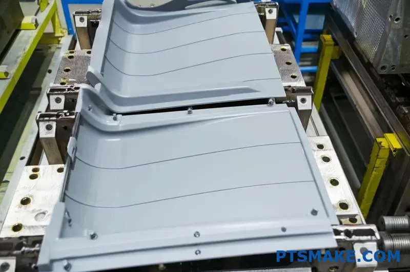
Stack Mold Technology: Multiplying Production Efficiency
Stack mold technology represents a groundbreaking approach to increasing production efficiency for large components without requiring proportionally larger molding machines.
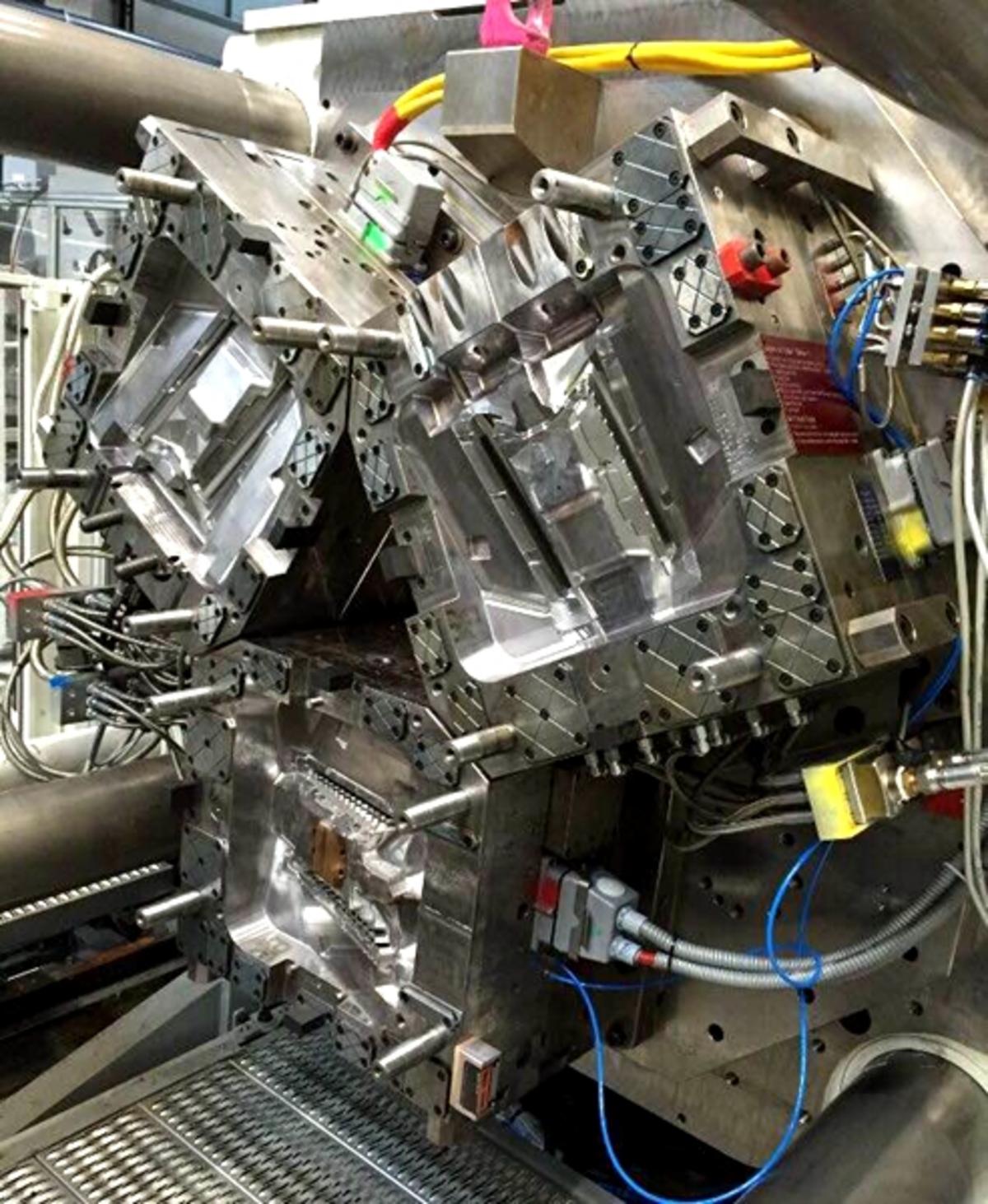
Stack Mold Configuration and Operation
Unlike conventional single-face molds, stack molds utilize multiple parting lines and mold faces arranged in a stacked configuration. A typical stack mold might include:
- A center section that moves with the machine’s core plate
- Two outer sections attached to the machine’s stationary and moving platens
- Specialized hot runner systems to deliver material to all cavities
- Synchronized mechanical or hydraulic actions to ensure proper operation
This configuration effectively doubles or even triples production output without requiring a substantially larger injection molding machine. For large components, this efficiency multiplier can transform production economics.
Production Advantages for High-Volume Large Parts
Stack mold technology delivers several distinct advantages for high-volume production of large components:
- Increased Output: Produces 2-4 times more parts per cycle than conventional molds
- Optimized Machine Utilization: Maximizes output from existing equipment
- Balanced Force Distribution: Provides more even clamping force across the mold
- Reduced shot-to-shot variation4: Consistent processing parameters across all cavities
- Energy Efficiency: Lower energy consumption per part produced
For applications like large automotive components, consumer appliance parts, or industrial containers produced in high volumes, stack molds can dramatically improve production economics while maintaining exceptional quality standards.
Implementation Challenges and Solutions
Implementing stack mold technology for large components presents several unique challenges:
- Complex Material Flow Management: Ensuring balanced filling across multiple cavities
- Precise Temperature Control: Maintaining uniform thermal conditions throughout the mold stack
- Mechanical Synchronization: Coordinating movements of multiple mold sections
- Maintenance Complexity: More sophisticated maintenance requirements than conventional molds
- Initial Investment Considerations: Higher upfront tooling costs despite long-term economics
Through proper engineering and advanced simulation techniques, these challenges can be effectively managed to unlock the remarkable production advantages stack mold technology offers for large component manufacturing.
Hybrid Approaches: Combining Technologies for Optimal Results
The most sophisticated large plastic injection molding services often involve hybrid approaches that combine multiple specialized techniques to address complex part requirements.
Gas-Assist Combined with Structural Foam
For exceptionally large components requiring both weight reduction and superior structural performance, combining gas-assist and structural foam technologies can deliver remarkable results. This hybrid approach:
- Uses structural foam for the primary part structure
- Implements gas-assist channels in strategic locations for additional reinforcement
- Creates optimized material distribution for maximum strength-to-weight ratio
- Delivers parts with excellent dimensional stability despite massive size
This combination proves particularly valuable for large components like automotive cargo management systems, where weight reduction, structural integrity, and dimensional stability are all critical requirements.
Multi-Material Large Component Solutions
Another hybrid approach involves multi-material or overmolding techniques for large components:
- Rigid/Flexible Combinations: Creating large parts with integrated seals or flexible zones
- Structural/Cosmetic Layers: Combining structural backing with aesthetic surface layers
- Metal/Plastic Hybrid Structures: Inserting metal reinforcements into large plastic components
- Multi-Durometer Applications: Varying hardness across different sections of massive parts
These sophisticated hybrid approaches enable designs that would be impossible through any single molding technique, expanding the possibilities for large component design and function.
Process Monitoring and Quality Control for Advanced Techniques
The specialized techniques used for large component manufacturing require equally sophisticated monitoring and quality control systems to ensure consistent results.
For gas-assist processes, precise control of gas pressure profiles and timing sequences is essential. At PTSMAKE, we implement advanced pressure transducers within mold cavities and specialized control algorithms to optimize gas parameters for each part.
Structural foam applications require careful monitoring of material temperature, CBA concentration, and injection speed to ensure consistent cellular structure development. Our process monitoring systems track these parameters in real-time, making micro-adjustments to maintain optimal conditions throughout production runs.
Stack mold operations demand synchronized monitoring of multiple cavities simultaneously, with balanced filling and packing parameters across all mold faces. Advanced vision systems and in-mold sensors help ensure consistent quality across all parts produced in each cycle.
Through these specialized monitoring approaches, manufacturers can maintain exceptional quality standards even when producing massive components using the most advanced molding techniques.
Quality Assurance for Oversized Molded Components
Have you ever wondered how those massive plastic components in your car, washing machine, or industrial equipment maintain such remarkable precision? Behind every successful large part lies a quality assurance system that’s as impressive as the molding technology itself.
Ensuring dimensional accuracy and structural integrity in large plastic injection molding services requires sophisticated quality systems that combine advanced measurement technologies, scientific process controls, and rigorous inspection protocols throughout the production lifecycle.
Dimensional Verification Challenges for Large Components
Quality assurance for oversized plastic components presents unique challenges that go beyond typical small-part inspection protocols. When dealing with parts that may span several feet in dimension, traditional measurement approaches often fall short.
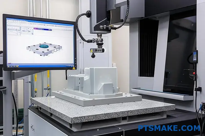
Coordinate Measuring Machine (CMM) Inspections
The cornerstone of dimensional verification for large molded components is the coordinate measuring machine (CMM). These sophisticated systems use touch probes or optical sensors to precisely map critical dimensions across massive parts.
For large components, we employ specialized CMM equipment with:
- Extended measurement envelopes (up to 2000mm x 3000mm x 1500mm)
- Temperature-compensated measurement algorithms
- Multi-point scanning capabilities for complex geometries
- Automated measurement sequencing for repeatability
The CMM process generates comprehensive inspection reports comparing actual dimensions against CAD models, with color-coded deviation maps highlighting any areas falling outside specification limits.
Laser Scanning and Structured Light Technologies
While CMMs excel at precise point-by-point measurement, newer technologies like laser scanning and structured light systems provide complementary capabilities especially valuable for large components:
| Technology | Key Advantages | Best Applications |
|---|---|---|
| Laser Scanning | Rapid collection of millions of data points | Complex contoured surfaces |
| Structured Light | Full-field analysis with submicron precision | Fine detail inspection |
| Photogrammetry | Measurement of very large components | Automotive body panels |
| Vision Systems | Real-time automated inspection | High-volume production |
At PTSMAKE, we’ve found that integrating these technologies creates a comprehensive measurement approach that captures both critical dimensions and overall part geometry with exceptional precision.
Managing Thermal Effects on Measurement
One of the most significant challenges in measuring large plastic components is managing thermal effects. Polymers have relatively high coefficients of thermal expansion, meaning even small temperature variations can cause measurable dimensional changes.
For precision verification, we maintain specialized temperature-controlled measurement rooms calibrated to 20°C ±1°C (68°F ±1.8°F). Additionally, parts are allowed to stabilize in this environment for 24-48 hours before final inspection, ensuring thermal equilibrium.
Scientific Molding Process Controls
Quality assurance for large components begins long before inspection – it starts with implementing scientific molding principles throughout the production process.
Decoupled Molding Approach
The scientific molding methodology known as "decoupled molding" separates the injection process into distinct phases:
- Fill Phase: Controlled by velocity to ensure complete cavity filling
- Pack Phase: Pressure-controlled to compensate for material shrinkage
- Hold Phase: Maintained until gate freeze-off to prevent backflow
- Cooling Phase: Temperature-controlled for dimensional stability
For large components, proper implementation of these phases becomes even more critical due to the longer flow distances and greater potential for variation across the part.
In-Mold Sensing Technologies
Large parts benefit tremendously from in-mold sensing technologies that provide real-time data during the molding process:
- Cavity Pressure Sensors: Monitor pressure at critical points throughout the cavity
- Temperature Sensors: Track mold and material temperatures during cycles
- Strain Gauges: Detect potential part deformation during ejection
- Flow Front Sensors: Verify complete cavity filling in remote areas
These sensors connect to sophisticated process monitoring systems that establish acceptable operating windows and automatically flag cycles that deviate from established parameters.
Process Capability Studies (Cpk)
For high-precision large components, we conduct comprehensive process capability studies to verify that our processes consistently meet specification requirements:
- Produce statistically significant sample quantities (typically 30+ parts)
- Measure critical dimensions across multiple production runs
- Calculate process capability indices (Cp and Cpk)
- Target Cpk values of 1.33 or higher for critical dimensions
- Implement process adjustments where capability falls short
Through these statistical analyses, we can quantifiably demonstrate process stability and predict long-term performance for large component manufacturing.
Advanced Statistical Process Control5 Systems
Statistical Process Control (SPC) systems automatically track key quality parameters throughout production runs, providing early warning of potential drift before specifications are violated. For large components, we implement multi-parameter SPC that monitors:
- Critical dimensions on sampled parts
- Process parameters from the injection molding machine
- Environmental conditions in the production area
- Material properties from incoming lots
This comprehensive approach ensures that all factors influencing large part quality remain within established control limits.
First Article Inspection (FAI) Protocols
First Article Inspection represents a critical milestone in large component production, establishing the baseline for subsequent quality verification.
Comprehensive Documentation Requirements
For large components, FAI documentation is particularly rigorous, typically including:
- Complete dimensional verification reports with all specified characteristics
- Material certification documentation
- Process parameter sheets detailing machine settings
- Appearance standards with approved reference samples
- Testing results for mechanical and physical properties
- Traceability documentation linking to raw materials
These documents serve as the quality baseline against which all future production will be measured.
Design of Experiments (DOE) for Process Optimization
Before finalizing the production process for large components, we often conduct structured Design of Experiments to identify optimal processing conditions:
- Identify critical process variables affecting quality
- Create experimental matrices varying these parameters
- Produce test parts under each condition set
- Measure results against target specifications
- Statistically analyze results to identify optimal settings
- Document findings in the FAI report
This scientific approach ensures that the production process starts with optimized parameters rather than relying on trial-and-error adjustments.
Cross-Functional Approval Process
FAI approval for large components typically involves a cross-functional team including:
- Quality engineering personnel
- Manufacturing engineering representatives
- Design engineering staff
- Customer quality representatives (when required)
- Material specialists
This collaborative approach ensures that all technical disciplines contribute to the quality verification process before full production begins.
Ongoing Production Monitoring and Control
Once production begins, maintaining quality consistency for large components requires sophisticated monitoring systems and inspection protocols.
Sampling Plans for Large Production Runs
For large components, we implement tailored sampling plans based on production volumes and criticality:
- Initial production often uses tightened inspection levels (Level II or III per ANSI/ASQ Z1.4)
- Statistical verification allows gradual transition to reduced sampling as stability is demonstrated
- Critical characteristics may require 100% inspection regardless of production history
- Automated measurement systems enable higher sampling rates without impacting production flow
These plans balance thorough verification against production efficiency requirements.
Non-Destructive Testing for Structural Integrity
Beyond dimensional verification, large components often undergo non-destructive testing to verify internal integrity:
- Ultrasonic testing to detect internal voids or inconsistencies
- X-ray inspection for critical structural areas
- Thermal imaging to identify potential stress concentrations
- Acoustic emission testing for structural components
These techniques help identify potential quality issues that might not be visible through conventional inspection methods.
Advanced Material Testing Protocols
For large components, material properties directly impact performance and longevity. Our ongoing quality assurance includes regular material testing:
- Tensile strength and elongation verification
- Impact resistance testing
- Heat deflection temperature validation
- Environmental stress crack resistance
- Accelerated aging studies
By monitoring material properties throughout production runs, we can detect subtle variations that might affect component performance before they impact finished products.
Traceability Systems for Quality Management
Complete traceability becomes especially important for large components, where production volumes may be lower but component value is significantly higher. Our quality system maintains comprehensive traceability including:
- Raw material lot documentation
- Process parameter records for each production run
- Operator identification and certification verification
- Equipment maintenance and calibration records
- Complete inspection data history
This traceability chain enables rapid root cause analysis should any issues arise, facilitating continuous improvement of both products and processes.
Through these comprehensive quality assurance approaches, large plastic injection molding services can consistently deliver components that meet the most demanding specifications, ensuring reliable performance throughout their service life.
Strategic Approaches to Large Part Production
Ever wondered why some large plastic parts seem flawlessly engineered while others warp, crack, or simply don’t hold up? The secret lies not in the machines or materials, but in the strategic design approaches that make or break success in large-scale manufacturing.
Optimizing large plastic injection molding services requires precise engineering strategies that balance wall thickness design, proper draft angles, strategic rib structures, and carefully selected gate locations to ensure consistent filling, uniform cooling, and dimensional stability across massive components.
Wall Thickness Optimization: The Foundation of Quality
When designing large plastic components, wall thickness represents perhaps the most critical design consideration. Unlike smaller parts where variations might be tolerable, large components magnify every design flaw, making wall thickness consistency essential.
Uniform Thickness Principles
The core principle for large part design is maintaining uniform wall thickness throughout the component. This approach delivers several critical benefits:
- Promotes even material flow during injection
- Ensures consistent cooling rates across the part
- Minimizes internal stresses that cause warpage
- Reduces sink marks on visible surfaces
- Prevents thickness-related structural weak points
At PTSMAKE, I’ve seen numerous projects where clients initially designed parts with significant thickness variations. These designs inevitably led to quality issues during production. By implementing uniform thickness principles, we’ve consistently achieved better outcomes.
The ideal wall thickness for large parts typically ranges from 2.5mm to 3.5mm for most applications, though this can vary based on material selection and structural requirements. When thicker sections are unavoidable, we implement strategic approaches like coring, ribbing, or gas-assist technology to maintain effective cooling while preserving structural integrity.
Transitioning Between Thicknesses
When thickness transitions are unavoidable in large components, gradual changes become essential. The standard practice is implementing transitions no greater than 40% of the nominal wall thickness over a distance of at least three times the wall thickness.
For example, transitioning from a 3mm wall to a 4.2mm section should occur over a minimum distance of 9mm to prevent stress concentration and uneven cooling. These gradual transitions are particularly important in large parts where the cooling differential between thick and thin sections can create significant internal stresses.
| Nominal Wall | Maximum Step | Minimum Transition Distance |
|---|---|---|
| 2.5mm | 1.0mm | 7.5mm |
| 3.0mm | 1.2mm | 9.0mm |
| 3.5mm | 1.4mm | 10.5mm |
| 4.0mm | 1.6mm | 12.0mm |
This calculated approach to thickness transitions helps maintain consistent material flow and cooling characteristics throughout large components, significantly reducing defects in finished parts.
Draft Angle Implementation for Successful Ejection
Draft angles represent another critical consideration that becomes increasingly important as part size increases. These angled surfaces facilitate smooth ejection from the mold, preventing damage and distortion during the manufacturing process.
Determining Optimal Draft Values
For large plastic components, standard draft angles often prove insufficient. While smaller parts might function with 0.5° draft, large components typically require:
- Minimum 1.0° draft for textured surfaces
- 0.5°-1.5° for smooth, non-textured areas
- 2.0°-3.0° for deep ribs and bosses
- 1.5°-2.5° for surfaces with light textures
The increased draft requirements stem from the greater surface area contact between the part and mold, which creates proportionally higher friction during ejection. Additionally, large parts are more susceptible to distortion during the ejection process, making proper draft even more critical.
Direction-Specific Draft Considerations
Draft angles must be designed relative to the ejection direction, which becomes more complex with large, multi-faceted components. At PTSMAKE, we analyze each surface individually to ensure appropriate draft relative to its specific ejection path.
For particularly challenging geometries, we often implement split-line designs6 that allow sections of the part to release in different directions, enabling proper draft for all surfaces while maintaining dimensional integrity.
null
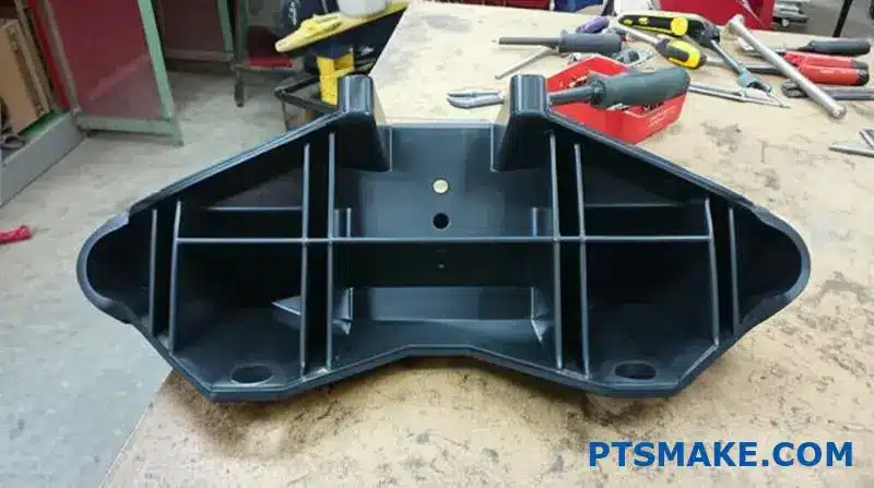
Structural Ribbing Strategies for Strength and Stability
Ribbing provides essential structural support in large components while maintaining reasonable wall thicknesses. However, improper rib design can create more problems than it solves, particularly in oversized parts.
Rib Thickness-to-Wall Ratio
The fundamental rule for rib design is maintaining appropriate thickness relative to the nominal wall. For large components, we typically recommend:
- Rib thickness at 40-60% of the adjoining wall thickness
- Maximum rib height of 3x the nominal wall thickness
- Radius at the base of the rib equal to 25-30% of wall thickness
- Minimum 0.5° additional draft on rib sidewalls beyond the base requirement
These proportions balance structural support against potential sink marks and cooling issues. When ribs are too thick relative to the wall, they create sink marks on opposite surfaces; when too thin, they fail to provide adequate support and may fill incompletely during molding.
Rib Layout Patterns for Large Surfaces
The arrangement of ribs across large surfaces significantly impacts both structural performance and manufacturability:
- Grid Patterns: Provide balanced support across expansive flat surfaces
- Radial Arrangements: Ideal for circular or curved sections
- Triangulated Structures: Deliver maximum rigidity with minimal material
- Parallel Systems: Enable consistent material flow during molding
For extremely large flat surfaces, we often implement a combination of primary and secondary rib systems. Primary ribs provide the main structural framework, while secondary ribs offer localized reinforcement in high-stress areas.
When designing rib patterns, maintaining consistent material flow paths becomes particularly important. Ribs should never create obstacles that impede material flow, as this can result in hesitation marks, weld lines, or incomplete filling in remote areas of large parts.
Gate Design and Placement for Optimal Material Flow
Perhaps no aspect of large part design is more critical than proper gate location and design. The gate represents the entry point for molten plastic into the mold cavity, and its design directly influences material flow, pressure distribution, and ultimately part quality.
Strategic Gate Locations for Massive Parts
For large components, multiple gates often become necessary to ensure complete filling before material solidification. The strategic placement of these gates requires careful consideration:
- Position gates in thicker sections when possible
- Maintain equal flow distances to extremities of the part
- Avoid placing gates on visible or cosmetic surfaces
- Consider structural integrity where gates connect to the part
- Account for weld line formation between converging flow fronts
Using sophisticated mold flow analysis software, we simulate various gate configurations to identify the optimal arrangement before finalizing tool design. This approach prevents costly trial-and-error adjustments during the sampling phase.
Gate Type Selection for Different Applications
Various gate designs offer specific advantages for different large part applications:
| Gate Type | Advantages | Best Applications |
|---|---|---|
| Fan Gates | Wide material distribution | Flat panels, large covers |
| Submarine Gates | Automatic vestige removal | Components with cosmetic surfaces |
| Edge Gates | Controlled filling pattern | Structural components, frames |
| Hot Tip Gates | Minimal gate vestiges | Visible surfaces requiring clean finish |
| Valve Gates | Precise control of injection pressure | Critical components with strict tolerances |
For particularly challenging large components, we often implement a sequential valve gate system that precisely controls the timing of material injection through multiple gates. This approach enables filling optimization that would be impossible with conventional gate designs.
Cooling System Design for Dimensional Stability
The cooling system design becomes increasingly critical as part size increases. Large components contain significantly more thermal energy and require carefully engineered cooling systems to maintain dimensional stability.
Balanced Cooling Approaches
Uniform cooling across large surfaces prevents differential shrinkage that leads to warpage and dimensional instability. Key strategies include:
- Maintaining consistent cooling channel distance from part surfaces
- Implementing conformal cooling designs that follow part geometry
- Creating independent cooling zones for areas with different thickness profiles
- Utilizing high-conductivity mold materials in critical areas
- Implementing thermal pins to reach areas inaccessible to conventional cooling channels
Through these approaches, we create balanced thermal management systems that extract heat uniformly from massive components, ensuring dimensional stability and consistency in production.
Cooling Time Optimization
The cooling phase typically represents the longest portion of the molding cycle, particularly for large parts. Optimizing cooling without compromising quality requires sophisticated approaches:
- Strategic turbulence induction in cooling channels
- Pressure-sensing ejection systems that detect solidification
- Multi-stage cooling profiles that adapt throughout the cycle
- Advanced materials with enhanced thermal conductivity
By implementing these techniques, we’ve successfully reduced cooling times by 15-30% for large components while maintaining or improving dimensional stability.
Through the strategic implementation of these design approaches, manufacturers can successfully produce large plastic components that meet demanding quality and performance requirements while maintaining production efficiency.
Full-Service Injection Molding: End-to-End Manufacturing
Ever wondered how those massive plastic parts in your car, refrigerator, or industrial equipment go from concept to finished product so seamlessly? Behind every large plastic component lies a sophisticated manufacturing ecosystem that few get to see but everyone benefits from.
Full-service large plastic injection molding services deliver comprehensive manufacturing solutions by integrating every phase from initial design consultation through final distribution, eliminating supply chain complexity while ensuring consistent quality control across the entire production lifecycle.
The Integrated Manufacturing Advantage
When it comes to producing large plastic components, fragmented supply chains create numerous challenges. Every hand-off between different vendors introduces potential for miscommunication, quality variations, and timeline extensions. This is why comprehensive manufacturing solutions have become increasingly valuable for companies seeking to streamline production of oversized plastic parts.
From Design Consultation to Manufacturing Reality
The journey from concept to finished product begins with collaborative design. At PTSMAKE, our engineering team works directly with clients to optimize designs specifically for large part manufacturability. This early engagement helps identify and address potential issues before they become costly problems.
A true end-to-end service approach includes:
- Design for Manufacturability (DFM) analysis specific to large components
- Material selection consultation based on performance requirements
- Prototyping options for concept validation
- Tooling design optimization for efficient production
- Clear communication channels throughout the process
This integrated approach eliminates the traditional gaps between design firms, toolmakers, and molders – gaps that often lead to finger-pointing when issues arise. Instead, a single team takes ownership of the entire process, creating accountability and continuity.
Prototyping Pathways for Large Components
Validating designs before committing to production tooling becomes even more critical with large components, where tooling investments are substantial. Comprehensive service providers offer multiple prototyping options to address different project needs:
- Rapid Prototyping: 3D printing, CNC machining, or vacuum casting to quickly visualize concepts
- Bridge Tooling: Aluminum or soft tools for limited production runs
- Prototype-to-Production: Progressive tooling approaches that evolve from prototype to final production
These options allow manufacturers to validate designs, conduct functional testing, and even perform limited market trials before investing in full production tooling. For large components where tooling costs can reach six figures, this approach significantly reduces development risk.
Advanced Tooling Development
The foundation of successful large component manufacturing lies in sophisticated tooling systems designed specifically for oversized applications.
Engineering for Scale
Creating tooling for large plastic components requires specialized expertise that goes beyond standard mold making. Key considerations include:
| Challenge | Strategic Solution |
|---|---|
| Material Flow Distance | Multi-gate systems with balanced runners |
| Uniform Cooling | Conformal cooling channels and thermal management |
| Part Ejection | Sequenced ejection systems to prevent distortion |
| Mold Stability | Reinforced steel structures to prevent deflection |
| Longevity | Premium steel selections for extended tool life |
These engineering considerations become exponentially more important as part size increases. A comprehensive service provider integrates tooling development with process engineering, ensuring the mold design accommodates both the part geometry and the intended manufacturing process.
Class 101 Production Tooling
For high-volume production of large plastic components, Class 101 tooling represents the gold standard. These precision-engineered molds are built for millions of cycles while maintaining tight tolerances. Full-service providers maintain in-house tooling capabilities with specialized equipment for handling massive mold bases weighing several tons.
The integration of tooling and molding operations enables continuous improvement through production feedback loops. When the same team maintains both the tooling and the molding process, adjustments can be implemented quickly without the delays typical of multi-vendor arrangements.
Production Molding Excellence
The core of any manufacturing solution is the production process itself. For large plastic components, this requires specialized equipment and expertise.
Large-Tonnage Injection Molding Capabilities
Production of oversized plastic components demands injection molding machines with clamping forces ranging from 500 to 4,000 tons. These massive machines represent substantial capital investments that specialized providers leverage across multiple projects.
Beyond raw machine capacity, successful large part molding requires:
- Specialized screw and barrel configurations for consistent material preparation
- Advanced process control systems for parameter optimization
- Robotic part removal systems to handle heavy components
- Real-time monitoring for quality assurance
By centralizing these specialized resources within a comprehensive service model, manufacturers can access capabilities that would be prohibitively expensive to develop internally.
Material Management for Volume Production
Large components consume significant material volumes, making efficient material management essential for cost control and quality consistency. Full-service providers implement sophisticated material handling systems including:
- Climate-controlled material storage to prevent moisture absorption
- Automated material delivery systems to ensure consistency
- Central drying systems with multiple hoppers for different materials
- Specialized additives and colorants for custom formulations
This infrastructure enables consistent production while optimizing material utilization – critical considerations when individual parts may consume several kilograms of engineering-grade resins.
Secondary Operations Integration
The manufacturing journey doesn’t end when parts exit the injection molding machine. Large components often require multiple secondary operations to deliver finished products.
Precision Assembly Capabilities
Many complex products require the assembly of multiple large components. Comprehensive manufacturing solutions include assembly capabilities tailored to oversized parts:
- Ultrasonic or vibration welding for joining large sections
- Mechanical fastening systems with automated torque control
- Adhesive bonding with controlled curing processes
- Insert installation and over-molding capabilities
By integrating assembly operations within the manufacturing workflow, producers eliminate transportation between facilities and maintain quality control throughout the process.
Decorative Finishing Technologies
Aesthetic considerations often play a crucial role in large component applications, particularly for visible consumer products. Full-service providers offer multiple finishing options:
- Painting and Coating: Custom colors, textures, and protective finishes
- Pad Printing: Logos, instructions, and regulatory markings
- Hot Stamping: Metallic accents and brand identifiers
- In-Mold Decoration: Films and appliqués applied during molding
These integrated finishing capabilities ensure consistent appearance across production runs while eliminating the logistics challenges of shipping large components between separate vendors.
Supply Chain Simplification
Perhaps the most significant advantage of end-to-end manufacturing solutions is the dramatic simplification of supply chain logistics.
Inventory Management Systems
Full-service providers implement comprehensive inventory management systems that track components throughout the production process. These systems provide:
- Real-time visibility into work-in-process inventory
- Automated reorder triggers for raw materials
- Finished goods management based on customer requirements
- Historical data for production planning optimization
For manufacturers producing large plastic components, effective inventory management directly impacts both cash flow and responsiveness to market demands.
Distribution and Logistics Support
Getting massive plastic components from production facilities to end users presents unique challenges. Comprehensive service providers offer integrated logistics solutions that address the specific requirements of oversized parts:
- Custom packaging engineered for component protection
- Consolidated shipping to minimize transportation costs
- Global logistics networks for international distribution
- Warehousing options for just-in-time delivery programs
By consolidating these functions within a single service relationship, manufacturers reduce administrative overhead while improving supply chain reliability.
Quality Assurance Across the Value Chain
Maintaining consistent quality across complex manufacturing processes requires systematic quality management7 approaches integrated at every stage.
Unified Quality Systems
End-to-end manufacturing solutions implement unified quality systems that maintain consistency from initial design through final delivery. These systems typically include:
- Document control processes that ensure current specifications
- Material certification and traceability protocols
- In-process inspection with statistical process control
- Final verification against customer requirements
- Closed-loop corrective action systems
This unified approach prevents the quality disconnects common in fragmented supply chains, where different quality standards or systems may be applied at different stages.
Continuous Improvement Programs
The most effective manufacturing partners implement structured continuous improvement programs that drive ongoing optimization. These programs leverage data collected throughout the manufacturing process to identify opportunities for:
- Cycle time reduction through process optimization
- Material utilization improvement to reduce costs
- Quality enhancement through defect elimination
- Energy efficiency gains through equipment optimization
This commitment to continuous improvement ensures that manufacturing processes evolve and improve throughout product lifecycles, delivering increasing value over time.
By integrating these comprehensive capabilities within a single manufacturing relationship, companies producing large plastic components can achieve significant competitive advantages through faster development cycles, consistent quality, and optimized total cost of ownership.
Learn how monitoring systems increase part quality and reduce costs. ↩
Discover how computer simulation optimizes material flow patterns and improves part quality. ↩
Learn how combining different fiber types creates synergistic performance improvements for large components. ↩
Learn how minimizing process variations leads to better part consistency and higher yields. ↩
Learn how statistical methods identify process trends before they become quality issues. ↩
Explore advanced techniques for creating complex parting lines in large mold designs. ↩
Discover how unified quality approaches reduce defects and improve consistency across production. ↩