Designing plastic parts can be a daunting challenge for many engineers. I’ve seen numerous projects fail due to overlooked design principles, resulting in manufacturing defects, increased costs, and project delays. These issues often surface late in the development cycle, causing significant setbacks and budget overruns.
Successful plastic part design requires a systematic approach focusing on four key elements: functional requirements, material selection, manufacturability, and assembly optimization. By following these principles, engineers can create designs that are both cost-effective and reliable.
Understanding Functional Requirements
Before diving into the design process, we must clearly define what the part needs to do. This includes:
- Operating environment conditions
- Load-bearing requirements
- Chemical resistance needs
- Temperature exposure ranges
- Expected product lifetime
Material Selection Criteria
The choice of material significantly impacts the success of your design. Consider these factors:
- Mechanical properties
- Chemical resistance
- Thermal characteristics
- Cost considerations
- Environmental impact
One critical aspect often overlooked is the material’s crystallinity1, which affects both processing parameters and final part properties.
Design for Manufacturability (DFM)
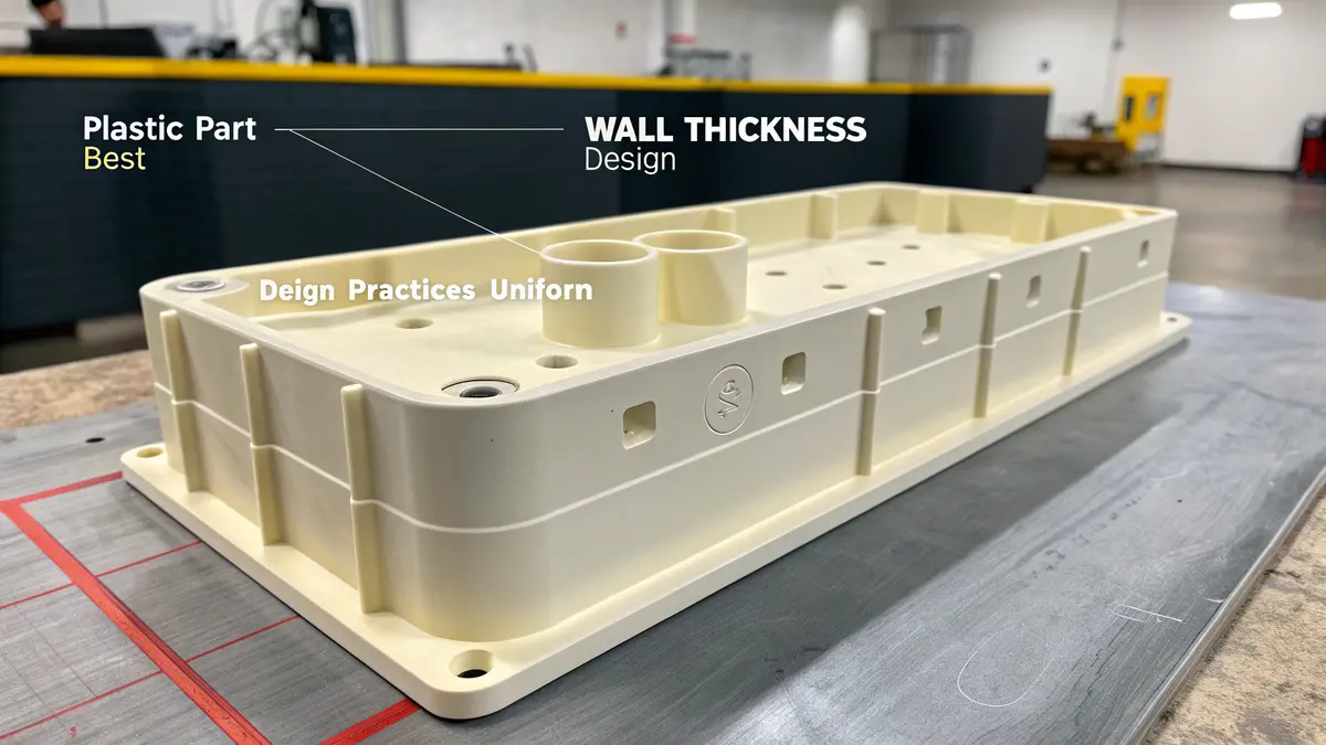
Wall Thickness Considerations
| Wall Thickness Aspect | Recommended Range | Impact on Production |
|---|---|---|
| Nominal thickness | 2.0-3.0mm | Optimal material flow |
| Maximum variation | ±10% | Prevents warpage |
| Rib thickness | 50-70% of wall | Reduces sink marks |
Draft Angles and Undercuts
Draft angles are essential for proper part ejection. I recommend:
- Minimum 1° draft for textured surfaces
- 0.5° draft for smooth surfaces
- Avoiding undercuts where possible
- Using side-actions only when necessary
Radius and Fillet Design
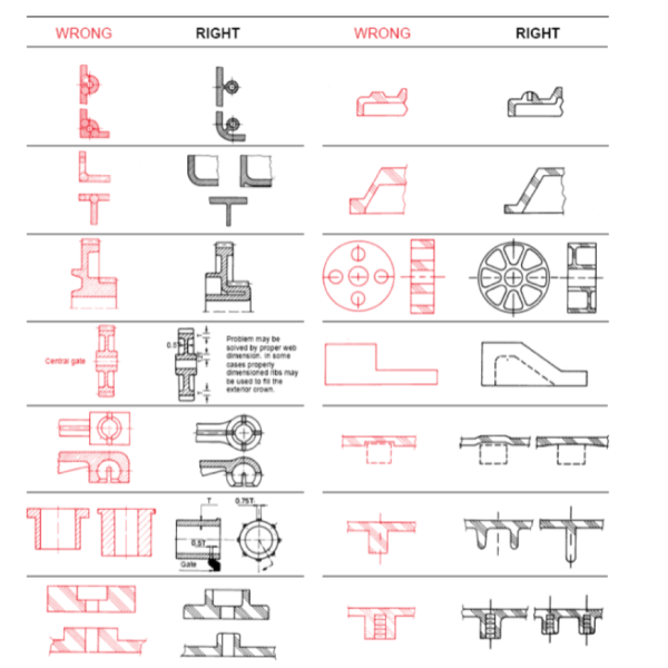
Sharp corners are stress concentrators and should be avoided:
- Outer corners: minimum radius of 0.5mm
- Inner corners: minimum radius of 1.0mm
- Uniform radius transitions
- Gradual thickness changes
Assembly Optimization
Snap Fit Design
Proper snap fit design ensures:
- Easy assembly
- Reliable retention
- Damage-free disassembly
- Cost-effective production
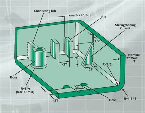
Bosses and Ribs
Design guidelines for structural features:
- Boss diameter: 2x wall thickness
- Rib height: 3x wall thickness
- Support gussets for tall features
- Proper spacing for material flow
Surface Finish and Aesthetics
Consider these aspects for appearance:
- Texture requirements
- Parting line location
- Gate location
- Ejector pin placement
Design Validation
Before finalizing the design:
- Conduct FEA analysis
- Create rapid prototypes
- Perform mold flow analysis
- Test assembly procedures
Through implementing these design principles, I’ve helped numerous clients at PTSMAKE achieve successful plastic part designs. The key is to consider all aspects early in the design phase, preventing costly modifications later. Remember that good design isn’t just about creating a part that works – it’s about creating one that can be manufactured efficiently and economically.
I always emphasize to our clients that successful plastic part design is iterative. Start with the basics, validate your assumptions, and refine based on feedback. This approach has consistently led to successful outcomes in our projects.
What is the minimum radius for plastic parts?
Designing plastic parts with incorrect corner radii can lead to devastating manufacturing failures. I’ve seen parts crack under minimal stress, warp during molding, and fail quality inspections – all because of poorly designed radii that created stress concentration points.
The minimum radius for plastic parts typically follows the 0.5x wall thickness rule for internal corners, while external radii should equal the internal radius plus wall thickness. This guideline ensures proper material flow and reduces stress concentration, preventing part failures.

Understanding the Importance of Corner Radii
When designing plastic parts, the stress concentration factor2 at corners significantly impacts part performance. I always emphasize to our clients that proper radius design is not just about aesthetics – it’s fundamental to part functionality. Here’s why radii matter:
Material Flow
- Improves mold filling patterns
- Reduces hesitation marks
- Prevents short shots during injection
- Ensures uniform cooling
Structural Integrity
- Distributes stress more evenly
- Reduces risk of part failure
- Enhances overall durability
- Improves impact resistance
Recommended Minimum Radius Guidelines
Based on extensive testing and real-world applications, I’ve developed this comprehensive guide for minimum radius recommendations:
| Wall Thickness (mm) | Minimum Internal Radius (mm) | Recommended External Radius (mm) |
|---|---|---|
| 0.5 | 0.25 | 0.75 |
| 1.0 | 0.50 | 1.50 |
| 1.5 | 0.75 | 2.25 |
| 2.0 | 1.00 | 3.00 |
| 2.5 | 1.25 | 3.75 |
| 3.0 | 1.50 | 4.50 |
Common Design Mistakes to Avoid
I regularly encounter these radius-related issues in plastic part designs:
Inconsistent Radii
- Creates uneven material flow
- Leads to unpredictable shrinkage
- Causes appearance defects
- Results in varying cooling rates
Sharp Corners
- Act as stress concentrators
- Increase risk of part failure
- Complicate mold release
- Create weak points in the design
Special Considerations for Different Materials
Different plastic materials require specific radius considerations:
Glass-Filled Materials
- Require larger radii due to reduced flow
- Minimum internal radius: 0.75x wall thickness
- Need gradual transitions
- More susceptible to stress concentration
Flexible Materials
- Can accommodate smaller radii
- Minimum internal radius: 0.3x wall thickness
- Less prone to stress cracking
- Better flow characteristics
Impact on Manufacturing Process
Proper radius design affects several manufacturing aspects:
Molding Cycle Time
- Optimized radii reduce cycle time
- Improve material flow speed
- Enable faster cooling
- Increase production efficiency
Tool Maintenance
- Reduces wear on mold corners
- Extends tool life
- Minimizes maintenance requirements
- Lowers production costs
Quality Control Considerations
I implement these quality control measures for radius verification:
Measurement Methods
- Digital inspection systems
- Profile projectors
- 3D scanning technology
- Coordinate measuring machines
Common Quality Issues
- Sink marks at thick sections
- Warpage from uneven cooling
- Flash at parting lines
- Surface finish inconsistencies
Cost Implications
Proper radius design impacts manufacturing costs:
Initial Design Phase
- Reduced design iterations
- Faster design approval
- Lower prototype costs
- Improved manufacturability
Production Phase
- Decreased scrap rate
- Improved yield
- Lower maintenance costs
- Increased tool longevity
Future Trends in Radius Design
The industry is evolving with new approaches to radius design:
Digital Solutions
- AI-powered design optimization
- Automated radius checking
- Simulation-driven design
- Real-time analysis tools
Advanced Materials
- New material-specific guidelines
- Innovative corner treatments
- Enhanced flow properties
- Improved stress resistance
This comprehensive approach to radius design helps ensure successful plastic part manufacturing while minimizing potential issues and optimizing production efficiency.
What are design considerations when designing a part?
Designing parts without proper consideration of manufacturing constraints often leads to costly revisions and production delays. Many engineers struggle with balancing design intent against manufacturability, resulting in parts that either can’t be produced efficiently or fail to meet performance requirements.
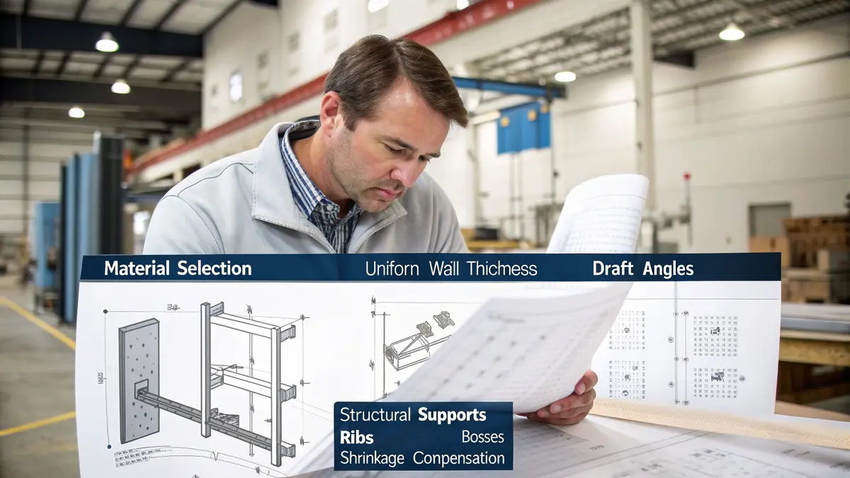
Successful part design requires careful attention to five key elements: material selection, wall thickness uniformity, draft angles, structural support features, and shrinkage compensation. These factors directly impact both manufacturability and part performance.
Material Selection Fundamentals
The choice of material forms the foundation of any successful part design. At PTSMAKE, I always emphasize how material properties influence both manufacturing processes and end-use performance. When selecting materials, we consider:
Mechanical Properties
- Tensile strength
- Impact resistance
- Flexural modulus
- Heat deflection temperature
Chemical Properties
- Resistance to UV exposure
- Chemical compatibility
- Moisture absorption
- Hygroscopic behavior3
Processing Requirements
- Melt flow characteristics
- Processing temperature range
- Mold temperature requirements
- Drying specifications
Wall Thickness Optimization
Maintaining uniform wall thickness is crucial for preventing manufacturing defects. Based on my experience at PTSMAKE, I recommend:
| Wall Thickness Range | Typical Applications | Key Benefits |
|---|---|---|
| 0.5mm – 1.0mm | Small electronic enclosures | Faster cooling, material savings |
| 1.0mm – 2.5mm | Consumer products | Good balance of strength and moldability |
| 2.5mm – 3.5mm | Structural components | Enhanced rigidity and stability |
| 3.5mm – 4.0mm | Heavy-duty applications | Maximum strength requirements |
Draft Angle Implementation
Draft angles are essential for proper part ejection from the mold. The general guidelines we follow include:
- Minimum 1° draft for textured surfaces
- 0.5° to 2° draft for smooth surfaces
- Additional draft for deep ribs and bosses
- Increased draft for grained or textured surfaces
Rib and Boss Design Principles
Structural features require careful consideration to prevent cosmetic defects while maintaining strength:
Rib Design Guidelines
- Maximum rib thickness: 60% of adjacent wall
- Height-to-thickness ratio: 2.5:1 to 3:1
- Minimum spacing between ribs: 2x wall thickness
- Gradual transitions at rib bases
Boss Configuration
- Boss diameter: 2x hole diameter
- Wall thickness: 60% of adjacent wall
- Support ribs for tall bosses
- Coring for thick sections
Shrinkage Compensation Strategies
Different materials exhibit varying shrinkage rates. Our approach includes:
Material-Specific Compensation
- Amorphous materials: 0.3-0.7%
- Semi-crystalline materials: 0.8-2.5%
- Glass-filled materials: 0.1-0.5%
Geometric Considerations
- Wall thickness variations
- Flow direction effects
- Gate location impact
- Cooling time optimization
Design for Assembly Integration
While focusing on individual design elements, we must consider assembly requirements:
Snap Fit Features
- Proper engagement angles
- Sufficient flexibility
- Stress concentration prevention
- Assembly clearances
Living Hinges
- Material selection for cyclic loading
- Thickness requirements
- Flex radius optimization
- Gate location considerations
Thread Design
- Thread pitch selection
- Core and cavity considerations
- Wear compensation
- Assembly torque requirements
At PTSMAKE, we ensure these design considerations are implemented early in the development process. This proactive approach helps our customers avoid costly modifications and achieve optimal part performance. I’ve found that successful part design requires balancing these various elements while maintaining focus on the end-use requirements and manufacturing constraints.
The key to successful part design lies in understanding how these various elements interact with each other. A change in material selection, for example, might require adjustments to wall thickness and draft angles. Similarly, the addition of structural features like ribs and bosses must be balanced against the potential for sink marks and other cosmetic defects.
What are design guidelines for injection molding plastic parts?
Designing plastic parts for injection molding can be overwhelming. Many engineers struggle with part failures, quality issues, and costly design revisions because they overlook critical design principles. I’ve seen projects delayed by months due to these preventable mistakes.
The key design guidelines for injection molding focus on proper wall thickness, draft angles, rib design, and gate location selection. These principles ensure part quality, reduce production costs, and minimize defects while maintaining dimensional accuracy and structural integrity.
Wall Thickness Considerations
Wall thickness is crucial for successful injection molding. Maintaining uniform wall thickness helps prevent warping, sink marks, and internal stresses. The optimal wall thickness depends on the material and part requirements:
| Material Type | Recommended Wall Thickness (mm) |
|---|---|
| ABS | 1.2 – 3.5 |
| Polycarbonate | 1.0 – 3.8 |
| Nylon | 0.8 – 3.0 |
| HDPE | 0.8 – 3.0 |
| POM | 0.8 – 3.0 |
Draft Angle Implementation
Draft angles are essential for easy part ejection. When designing plastic parts, incorporate adequate draft angles on all walls parallel to the mold opening direction. The parting line4 location affects draft angle requirements:
- Textured surfaces: 3° minimum draft
- Smooth surfaces: 1° minimum draft
- Deep ribs or posts: 2-3° draft
- External walls: 1-2° draft
Rib and Boss Design
Ribs provide structural support while minimizing material usage. Follow these guidelines:
- Rib thickness: 50-60% of adjoining wall thickness
- Rib height: Maximum 3 times the wall thickness
- Spacing between ribs: Minimum 2 times wall thickness
- Base radius: 25-50% of wall thickness
Gate Location Selection
Proper gate location affects part quality and appearance:
- Place gates in thick sections
- Avoid gates on visible surfaces
- Consider multiple gates for large parts
- Allow adequate flow length
- Account for weld line formation
Corner and Radius Design
Sharp corners create stress concentrations and molding difficulties:
- Inside radius: Minimum 0.5mm
- Outside radius: Minimum 1.5 times wall thickness
- Maintain consistent wall thickness around corners
- Avoid thick sections at corners
Material Selection Considerations
Different materials have unique processing requirements:
Amorphous materials
- Lower shrinkage rates
- Better dimensional stability
- Examples: ABS, PC, PMMA
Semi-crystalline materials
- Higher shrinkage rates
- Better chemical resistance
- Examples: PP, PE, POM
Cooling Channel Design
Proper cooling channel design ensures uniform part cooling:
- Channel diameter: 8-12mm typical
- Channel spacing: 3-4 times diameter
- Distance from part surface: 1.5-2 times diameter
- Maintain consistent cooling circuit length
- Consider conformal cooling for complex geometries
Surface Finish Requirements
Surface finish affects both aesthetics and functionality:
| Finish Type | SPI Number | Application |
|---|---|---|
| High Polish | A1 | Optical parts |
| Semi-Polish | A2 | Visible surfaces |
| Matte | B1 | Non-visible parts |
| Textured | C1 | Grip surfaces |
Undercut Management
Minimize undercuts where possible:
- Use side actions for necessary undercuts
- Consider sliding cores for complex features
- Design snap fits with appropriate relief
- Calculate side action travel requirements
Assembly Considerations
Design for efficient assembly:
- Include alignment features
- Standardize snap fit dimensions
- Consider ultrasonic welding requirements
- Plan for insert molding when needed
- Design self-locating features
Remember, successful injection molding design requires careful consideration of all these elements. Each component affects the others, creating an interconnected system where changes in one area can impact the entire part’s manufacturability and quality.
How does wall thickness affect plastic part design?
Designing plastic parts with inconsistent wall thickness is like building a house with varying foundation depths – it’s a recipe for disaster. Many engineers struggle with this fundamental aspect, leading to costly production issues, quality defects, and project delays.
Wall thickness is a critical factor in plastic part design that directly impacts structural integrity and manufacturability. The ideal thickness typically ranges from 0.5mm to 5mm, with uniform distribution being key to preventing common defects like sink marks and internal stresses.
Understanding the Impact of Wall Thickness
Wall thickness affects every aspect of plastic part production. In my experience working with various projects at PTSMAKE, I’ve observed that proper wall thickness design can make the difference between a successful product and a failed one. The crystallization rate5 of the plastic material during cooling is directly influenced by wall thickness variations.
Optimal Wall Thickness Guidelines
Here’s a comprehensive guide for different plastic materials:
| Material Type | Recommended Thickness (mm) | Maximum Thickness (mm) |
|---|---|---|
| ABS | 1.2 – 3.5 | 4.0 |
| Polycarbonate | 0.8 – 4.0 | 4.5 |
| Nylon | 0.8 – 3.0 | 3.5 |
| HDPE | 0.8 – 2.5 | 3.0 |
| POM | 0.8 – 3.0 | 3.5 |
Common Design Challenges
Sink Marks and Voids
Thick sections in plastic parts cool slower than thin sections, creating sink marks on the surface. To prevent this:
- Keep wall thickness uniform whenever possible
- Design gradual transitions between different thicknesses
- Implement proper cooling channels in the mold
Warpage Control
Uneven cooling caused by varying wall thickness can lead to warpage. Our solution includes:
- Using ribs and gussets instead of thick walls
- Maintaining thickness ratios below 3:1
- Strategic placement of cooling lines in the mold
Material-Specific Considerations
Different materials behave uniquely during the injection molding process:
Amorphous Materials
- More forgiving with thickness variations
- Better flow characteristics
- Lower shrinkage rates
Semi-crystalline Materials
- More sensitive to thickness changes
- Higher shrinkage rates
- Require more precise temperature control
Design Optimization Techniques
Structural Requirements
When designing for strength:
- Use ribs instead of increasing wall thickness
- Maintain rib thickness at 60% of adjacent wall
- Place ribs in high-stress areas
Cost Efficiency
To optimize material usage:
- Eliminate unnecessary thick sections
- Design hollow features where possible
- Consider core-outs in thick areas
Quality Control Measures
At PTSMAKE, we implement several quality control measures:
- Digital simulation before production
- First article inspection
- Regular process monitoring
- Dimensional stability checks
Production Efficiency
Proper wall thickness design impacts:
- Cycle time optimization
- Material usage efficiency
- Tool longevity
- Production costs
Future Considerations
As manufacturing technology evolves, we’re seeing:
- Advanced simulation capabilities
- New materials with different requirements
- Improved cooling solutions
- Better process control methods
By understanding and implementing these wall thickness principles, designers can create more efficient, cost-effective, and high-quality plastic parts. Our experience shows that careful attention to wall thickness during the design phase prevents costly modifications later in production.
This comprehensive approach to wall thickness design has helped us deliver superior products to our clients across various industries, from automotive components to consumer electronics. The key is maintaining a balance between design requirements and manufacturing constraints while considering material properties and end-use applications.
Why is draft important in plastic part design?
Imagine designing a plastic part only to discover it’s stuck in the mold like a stubborn puzzle piece. This nightmare scenario happens more often than you’d think, causing production delays and costly damage. Without proper draft angles, even the simplest plastic parts can become manufacturing disasters.
Draft angles are essential design elements in plastic injection molding that allow parts to be easily removed from the mold. By incorporating a slight taper (typically 1-2 degrees) on vertical walls, manufacturers can ensure smooth part ejection and maintain surface quality.
Understanding Draft Angles
The concept of draft angles might seem simple, but it’s a crucial aspect of plastic part design that requires careful consideration. Draft angles create a slight taper on vertical surfaces, allowing the part to release from the mold without resistance. The parting line serves as the reference point from which draft angles are measured.
Factors Affecting Draft Angle Selection
Surface Texture and Finish
Different surface textures require varying draft angles:
| Surface Type | Recommended Draft Angle |
|---|---|
| Smooth Finish | 1° – 2° |
| Light Texture | 2° – 3° |
| Medium Texture | 3° – 5° |
| Deep Texture | 5° – 7° |
Material Properties
The material chosen for your part plays a significant role in determining the appropriate draft angle:
- Rigid materials like glass-filled nylon may require larger draft angles
- Flexible materials like TPE can sometimes work with smaller draft angles
- Crystalline materials often need more draft due to their shrinkage characteristics
Common Draft-Related Challenges
Depth Considerations
Deeper parts generally require more draft than shallow ones. For every inch of depth, consider adding an extra 0.5° to 1° of draft to ensure proper release. This is especially important for parts with significant vertical walls.
Internal Features
Internal features often require more draft than external ones because:
- They shrink onto the core
- Access for polishing is limited
- Ejection forces are more concentrated
Best Practices for Draft Implementation
Early Design Integration
- Include draft considerations during the initial design phase
- Use CAD software to analyze draft requirements
- Consider draft impact on part functionality
Strategic Draft Placement
- Apply more draft where ejection forces are highest
- Maintain uniform wall thickness when applying draft
- Consider the impact on assembly requirements
Quality Control Measures
- Use mold flow analysis to validate draft angles
- Implement proper cooling strategies
- Monitor part quality during initial production runs
Economic Impact of Proper Draft Design
The implementation of appropriate draft angles affects various aspects of production:
Production Efficiency
- Reduced cycle times
- Lower rejection rates
- Improved part quality
- Decreased maintenance requirements
Cost Considerations
- Initial mold design costs
- Long-term production savings
- Reduced scrap rates
- Extended mold life
Advanced Draft Considerations
Complex Geometries
When dealing with complex part geometries:
- Use variable draft angles where necessary
- Consider split-line locations carefully
- Account for undercuts and side actions
Material-Specific Requirements
Different materials require specific draft considerations:
| Material Type | Minimum Draft Angle |
|---|---|
| ABS | 1.5° |
| Polycarbonate | 1° |
| Polypropylene | 0.5° |
| Glass-Filled Materials | 2° – 3° |
Surface Finish Impact
The relationship between surface finish and draft:
- Polished surfaces may work with minimal draft
- Textured surfaces require additional draft
- EDM surfaces need intermediate draft angles
Benefits of Modern Draft Analysis Tools
Modern design tools offer significant advantages:
Digital Validation
- Real-time draft analysis
- Interference checking
- Flow pattern visualization
Optimization Capabilities
- Automatic draft angle suggestions
- Performance simulations
- Material behavior predictions
Through proper draft angle implementation, manufacturers can achieve:
- Consistent part quality
- Reduced production costs
- Improved cycle times
- Extended mold longevity
These benefits make draft angle consideration a crucial aspect of successful plastic part design and manufacturing.
What role do ribs and bosses play in plastic parts?
Designing plastic parts with optimal structural integrity while maintaining cost-effectiveness is a constant challenge. Many engineers struggle with parts that either use too much material or suffer from structural weaknesses, leading to failures and costly redesigns.
Ribs and bosses are critical design elements in plastic parts that provide structural support and mounting capabilities. These features enhance part strength and functionality while minimizing material usage, making them essential components in efficient plastic part design.
Understanding Rib Design Principles
The effectiveness of ribs in plastic parts depends heavily on proper design implementation. I’ve found that successful rib design requires careful consideration of several key factors:
- Height-to-thickness ratio: Ribs should maintain a height that’s no more than 3 times the wall thickness to prevent warping
- Spacing: The distance between ribs should be at least 2-3 times the wall thickness
- Draft angles: A minimum of 0.5° draft angle per side ensures proper part ejection
- Corner transitions: Proper radiusing6 at the base helps prevent stress concentration
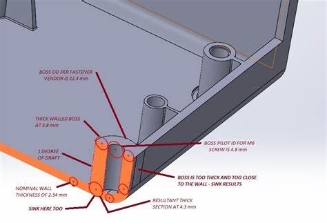
Boss Design Fundamentals
Bosses serve as crucial mounting points in plastic parts. When designing bosses, I always consider these essential elements:
Core Dimensions
- Inner diameter: Based on specific fastener requirements
- Outer diameter: Typically 2-2.5 times the inner diameter
- Height: Usually determined by fastener length and assembly requirements
Structural Considerations
- Support ribs: Adding gussets when boss height exceeds 3 times its diameter
- Wall thickness: Maintaining 60% of nominal wall thickness for supporting features
- Draft angles: Incorporating 1-2° draft for proper molding
Material Flow and Thickness Guidelines
The relationship between wall thickness and material flow significantly impacts part quality. Here’s a detailed breakdown:
| Feature Type | Recommended Thickness | Purpose |
|---|---|---|
| Main Wall | 100% (nominal) | Base reference |
| Ribs | 50-70% of nominal | Prevent sink marks |
| Bosses | 60-80% of nominal | Structural integrity |
| Gussets | 50-60% of nominal | Support features |
Optimizing for Manufacturing
At PTSMAKE, I emphasize these key considerations for successful rib and boss implementation:
Sink Mark Prevention
- Strategic rib placement
- Proper thickness ratios
- Gradual transitions at intersections
Moldability Enhancement
- Adequate draft angles
- Proper venting locations
- Optimized cooling channel placement
Structural Integrity
- Load distribution analysis
- Stress concentration prevention
- Material flow optimization
Common Design Mistakes to Avoid
Through experience, I’ve identified several critical errors that should be avoided:
Geometric Issues
- Excessive rib height without proper support
- Insufficient draft angles
- Sharp corners causing stress concentration
Material Considerations
- Improper thickness ratios leading to sink marks
- Inadequate flow paths causing fill issues
- Poor gate location affecting part strength
Manufacturing Challenges
- Complex geometries preventing proper cooling
- Insufficient support for tall features
- Inadequate ejection considerations
Impact on Part Performance
Well-designed ribs and bosses contribute significantly to part performance:
Structural Benefits
- Enhanced flexural rigidity
- Improved impact resistance
- Better load distribution
Material Efficiency
- Reduced material usage
- Lower part weight
- Improved cost-effectiveness
Quality Improvements
- Better dimensional stability
- Reduced warpage
- Consistent part appearance
Integration with Other Design Elements
Successful implementation requires consideration of:
Assembly Requirements
- Clearance for tools
- Accessibility for fasteners
- Alignment features
Environmental Factors
- Temperature effects
- Chemical exposure
- UV resistance
Production Considerations
- Cycle time optimization
- Tool maintenance
- Quality control requirements
The strategic use of ribs and bosses represents a crucial aspect of plastic part design, requiring careful balance between structural requirements and manufacturing constraints. These features, when properly implemented, significantly enhance part performance while maintaining efficient material usage and manufacturability.
How do gate locations impact plastic injection molding?
When manufacturing injection molded parts, many clients come to me frustrated with visible defects and quality issues in their products. These problems often trace back to one critical yet frequently overlooked aspect – gate location. Poor gate placement can turn a perfect design into a costly manufacturing nightmare.
Gate location serves as the entry point for molten plastic into the mold cavity. Its placement significantly influences material flow, part quality, and production efficiency. Proper gate positioning helps prevent common defects like weld lines, air traps, and uneven filling while ensuring optimal part aesthetics and structural integrity.
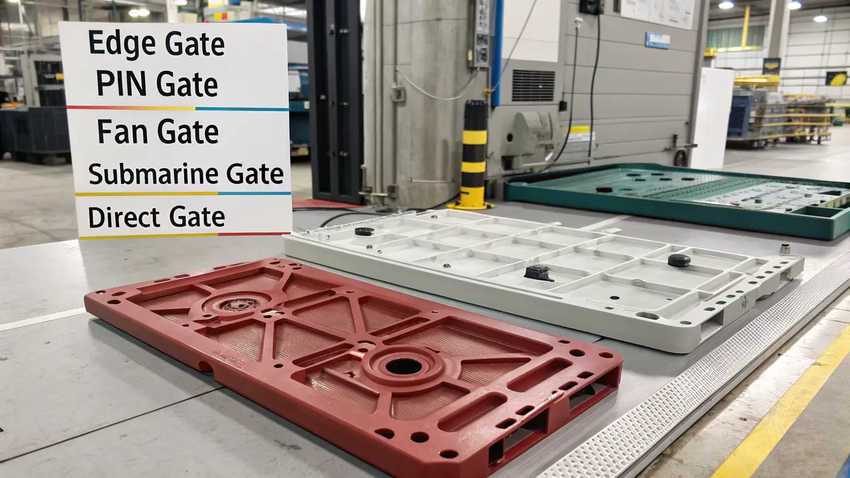
Understanding Gate Types and Their Applications
Different gate types serve various purposes in injection molding. I’ve categorized the main types based on their applications:
| Gate Type | Best Applications | Advantages | Limitations |
|---|---|---|---|
| Edge Gate | Flat parts, basic geometries | Easy to remove, good for automation | Limited to side entry |
| Pin Gate | Small parts, precise filling | Minimal gate mark, good for circular parts | Size limitations |
| Fan Gate | Wide, flat parts | Even material distribution | Difficult gate removal |
| Submarine Gate | High-volume production | Automatic degating | Complex tool design |
| Direct Gate | Large parts, thick sections | Simple design, efficient filling | Visible gate mark |
Critical Factors in Gate Location Selection
The success of your injection molded part heavily depends on several key factors when determining gate location:
Part Geometry Considerations
The rheological behavior7 of plastic material during injection requires careful analysis of part geometry. I always consider:
- Flow length to thickness ratio
- Natural flow paths
- Geometric transitions
- Wall thickness variations
Material Flow Requirements
Different materials have unique flow characteristics that influence gate placement:
- Crystalline vs. amorphous materials
- Melt viscosity
- Thermal sensitivity
- Flow length capabilities
Quality and Aesthetic Requirements
Gate location directly impacts visual and structural qualities:
- Visible surfaces
- Structural integrity zones
- Cosmetic requirements
- Weld line positioning
Impact on Common Molding Defects
Gate location significantly influences various molding defects:
Air Traps and Venting
Proper gate placement helps prevent:
- Trapped air pockets
- Burn marks
- Incomplete filling
- Surface defects
Weld Lines Management
Strategic gate positioning helps control:
- Weld line location
- Strength at meeting points
- Visual appearance
- Structural integrity
Flow-Related Issues
Optimal gate location addresses:
- Short shots
- Hesitation marks
- Flow marks
- Jetting
Advanced Considerations for Complex Parts
Complex parts require additional analysis:
Multi-Cavity Molds
For multi-cavity applications, consider:
- Balanced filling
- Runner system design
- Cavity-to-cavity consistency
- Production efficiency
High-Precision Components
Critical applications demand attention to:
- Dimensional stability
- Minimal warpage
- Precise material control
- Uniform shrinkage
At PTSMAKE, we utilize advanced mold flow analysis software to optimize gate locations. This scientific approach helps us:
- Predict material flow patterns
- Identify potential defect areas
- Optimize cooling efficiency
- Enhance overall part quality
Impact on Production Efficiency
Proper gate location affects various production aspects:
Cycle Time Optimization
- Faster filling times
- Efficient cooling
- Reduced pressure requirements
- Better material distribution
Maintenance Considerations
- Easy gate removal
- Reduced wear on mold components
- Simplified cleaning procedures
- Extended tool life
By carefully considering these factors and utilizing advanced simulation tools, we consistently achieve optimal results in injection molding projects. Our systematic approach to gate location selection has helped numerous clients overcome challenging manufacturing issues and achieve superior product quality.
How can shrinkage be managed in plastic part design?
Struggling with dimensional accuracy in plastic parts? I’ve seen countless manufacturers face costly rework and production delays due to unexpected shrinkage issues. When not properly managed, shrinkage can turn a perfect design into a rejected batch, causing headaches for everyone involved.
Managing shrinkage in plastic part design requires a comprehensive approach combining precise mold design adjustments, careful material selection, and optimized processing parameters. By understanding and accounting for material-specific shrinkage rates, manufacturers can ensure dimensional accuracy and part quality.
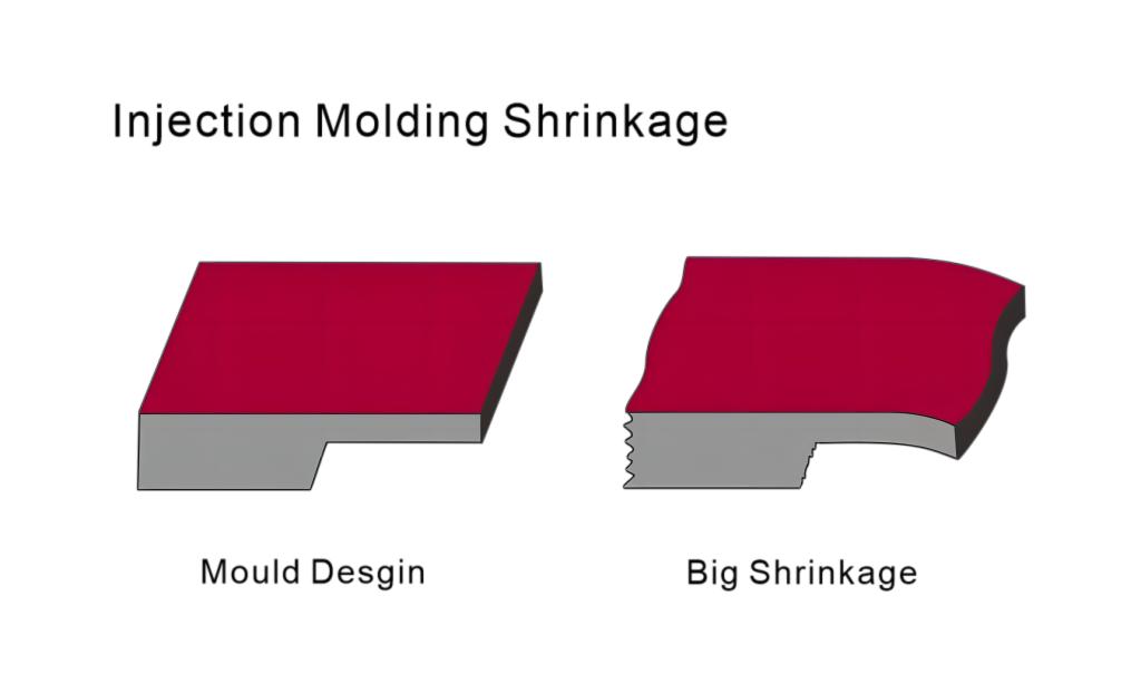
Understanding Material Shrinkage Characteristics
Different plastic materials exhibit varying volumetric shrinkage8 behavior during cooling. At PTSMAKE, we’ve developed a systematic approach to material selection based on shrinkage characteristics. Here’s a breakdown of common plastic materials and their typical shrinkage rates:
| Material Type | Linear Shrinkage Rate (%) | Shrinkage Uniformity |
|---|---|---|
| ABS | 0.4-0.7 | High |
| Polypropylene | 1.2-2.0 | Medium |
| Polyethylene | 1.5-3.0 | Low |
| Polycarbonate | 0.5-0.7 | High |
| Nylon | 0.8-2.0 | Medium |
Design Compensation Strategies
The key to managing shrinkage starts with proper design compensation. I recommend implementing these essential strategies:
Wall Thickness Optimization
- Maintain uniform wall thickness throughout the part
- Avoid sudden thickness transitions
- Design with recommended thickness ranges for specific materials
Draft Angle Considerations
- Increase draft angles by 1-2° to account for shrinkage
- Apply additional draft for deeper parts
- Consider material-specific shrinkage when calculating draft angles
Process Parameter Optimization
Control over processing parameters significantly impacts shrinkage management:
Mold Temperature Control
- Maintain consistent mold temperature
- Use appropriate cooling channel design
- Monitor temperature variations across the mold
Injection Pressure Settings
- Optimize holding pressure duration
- Adjust injection speed based on material characteristics
- Balance filling and packing phases
Advanced Cooling System Design
Proper cooling system design is crucial for uniform shrinkage:
Cooling Channel Layout
- Position channels for uniform heat removal
- Maintain consistent channel diameter
- Ensure proper channel spacing
Cooling Time Optimization
- Calculate minimum cooling time based on wall thickness
- Consider material thermal properties
- Monitor part temperature at ejection
Material-Specific Considerations
Different materials require specific approaches:
Crystalline Materials
- Allow for higher shrinkage rates
- Implement longer cooling times
- Consider gate location carefully
Amorphous Materials
- Monitor cooling rate consistency
- Maintain appropriate mold temperature
- Control packing pressure precisely
Quality Control Measures
Implementing robust quality control procedures ensures consistent results:
Dimensional Monitoring
- Regular part measurements
- Statistical process control implementation
- Documentation of shrinkage patterns
Process Documentation
- Record optimal processing parameters
- Maintain material-specific setting logs
- Document successful shrinkage compensation strategies
Common Troubleshooting Solutions
When shrinkage issues arise, consider these solutions:
Dimensional Issues
- Adjust mold dimensions based on measured shrinkage
- Modify cooling system layout
- Review material selection
Warpage Problems
- Balance cooling across the part
- Adjust processing temperatures
- Modify wall thickness design
At PTSMAKE, we’ve successfully implemented these strategies across numerous projects. Our experience shows that effective shrinkage management requires a holistic approach combining design expertise, material knowledge, and process control. By carefully considering each aspect of the manufacturing process, we consistently achieve tight tolerances and high-quality parts that meet or exceed customer specifications.
Understanding and managing shrinkage is not just about applying standard compensation factors – it requires a deep understanding of material behavior, process dynamics, and design principles. Through careful attention to these details and continuous monitoring of results, we can effectively control shrinkage and produce high-quality plastic parts that consistently meet dimensional requirements.
What special features should be considered in plastic part design?
Designing plastic parts with special features can be a daunting challenge. Many engineers struggle with balancing functionality and manufacturability, often leading to costly design revisions or production delays. The complexity of these features can make the difference between a successful product and a manufacturing nightmare.
Special features in plastic part design require careful consideration of manufacturing constraints and end-use requirements. Key elements include snap fits, living hinges, undercuts, and textured surfaces, each serving specific functional purposes while demanding precise design attention to ensure successful production.
Understanding Snap Fits
Snap fits are essential features that revolutionize assembly processes. I’ve found that successful snap fit design requires careful attention to several key factors:
- Material Selection: Different materials exhibit varying degrees of flexibility and strength
- Engagement Angle: Typically between 30-45 degrees for optimal performance
- Retention Force: Must balance easy assembly with secure holding power
- Wall Thickness: Critical for preventing stress concentration and breakage
The key to successful snap fit design lies in the strain rate9 calculation, which determines the material’s behavior during assembly.
Living Hinge Design Considerations
Living hinges offer unique advantages in plastic part design:
Design Parameters
- Thickness: Usually 0.2-0.3mm for optimal flexibility
- Material Selection: Polypropylene (PP) is preferred due to its excellent fatigue resistance
- Radius: Sharp corners must be avoided to prevent stress concentration
Performance Factors
| Factor | Requirement | Impact |
|---|---|---|
| Flex Life | >1 million cycles | Product longevity |
| Operating Temperature | -20°C to 80°C | Environmental stability |
| Mold Flow | Parallel to hinge | Structural integrity |
Managing Undercuts Effectively
Undercuts present unique challenges in injection molding:
Types of Undercuts
External Undercuts
- Require side actions or slides
- Impact cycle time and tool cost
Internal Undercuts
- Need collapsible cores
- Affect part ejection mechanics
Design Strategies
- Minimize depth where possible
- Consider split line location carefully
- Evaluate alternative designs that might eliminate undercuts
Surface Texturing Techniques
Surface textures serve both aesthetic and functional purposes:
Texture Categories
Functional Textures
- Anti-slip properties
- Light diffusion
- Wear resistance
Aesthetic Textures
- Leather grain
- Wood grain
- Geometric patterns
Design Guidelines
- Draft angle must increase with texture depth
- Pattern orientation should align with mold opening
- Depth-to-width ratio must be considered for proper filling
Material Selection Impact
The choice of material significantly influences special feature performance:
| Material | Snap Fit Performance | Living Hinge Capability | Texture Retention |
|---|---|---|---|
| PP | Excellent | Excellent | Good |
| ABS | Good | Poor | Excellent |
| PC | Very Good | Poor | Very Good |
| POM | Excellent | Poor | Fair |
Manufacturing Considerations
To ensure successful production:
Tool Design
- Proper venting
- Cooling channel layout
- Gate location optimization
Process Parameters
- Injection pressure control
- Temperature management
- Cooling time optimization
Quality Control
- Dimensional verification
- Functional testing
- Visual inspection
Cost Optimization Strategies
I recommend considering these factors for cost-effective design:
Design Simplification
- Reduce complexity where possible
- Combine features when feasible
- Standardize dimensions
Material Selection
- Balance cost with performance
- Consider recycled materials
- Optimize material usage
Manufacturing Efficiency
- Minimize cycle time
- Reduce secondary operations
- Optimize tool design
Maintenance and Longevity
For long-term success:
Regular Tool Maintenance
- Monitor wear points
- Clean venting channels
- Check alignment features
Quality Monitoring
- Track dimensional stability
- Monitor feature performance
- Document wear patterns
Process Optimization
- Fine-tune parameters
- Monitor cycle times
- Adjust as needed
Through careful consideration of these special features and their implementation requirements, we at PTSMAKE ensure optimal design and manufacturing outcomes. Our approach combines technical expertise with practical experience to deliver parts that meet both functional requirements and manufacturing constraints.
Understand how crystallinity impacts plastic properties for better material selection. ↩
Learn about how stress concentration affects part performance and design optimization techniques. ↩
Understand material moisture absorption effects to ensure optimal performance and durability in part design. ↩
Learn about parting lines to enhance mold efficiency and improve part quality in injection molding. ↩
Learn how wall thickness influences crystallization for better plastic part quality. ↩
Learn about stress reduction techniques that enhance the strength of your plastic part designs. ↩
Understanding rheological behavior enhances injection molding, improving flow characteristics and product quality. ↩
Learn about how shrinkage affects mold design and part quality for improved production outcomes. ↩
Understand strain rate for better material performance during assembly processes. ↩