When machining 5083 aluminum, many manufacturers struggle with maintaining consistent surface finishes and dimensional accuracy. I’ve noticed this challenge often leads to costly rework and project delays, especially in marine and aerospace applications.
The key considerations for 5083 aluminum machining include using the right cutting speed (1,000-2,500 SFM), maintaining sharp cutting tools, controlling chip formation, and ensuring proper coolant flow. These factors directly impact the part quality and machining efficiency.
At PTSMAKE, I’ve worked with numerous customers who initially faced difficulties with 5083 aluminum machining. Let me share some tested strategies we’ve developed for optimal results. In the following sections, I’ll explain the specific cutting parameters, tool selection, and cooling techniques that have proven successful in our operations.
What Is 5083 Aluminum?
Are you struggling to choose the right aluminum alloy for your marine or aerospace projects? Many engineers face challenges when selecting materials that can withstand harsh environments while maintaining structural integrity. The wrong choice could lead to premature corrosion, structural failures, and costly replacements.
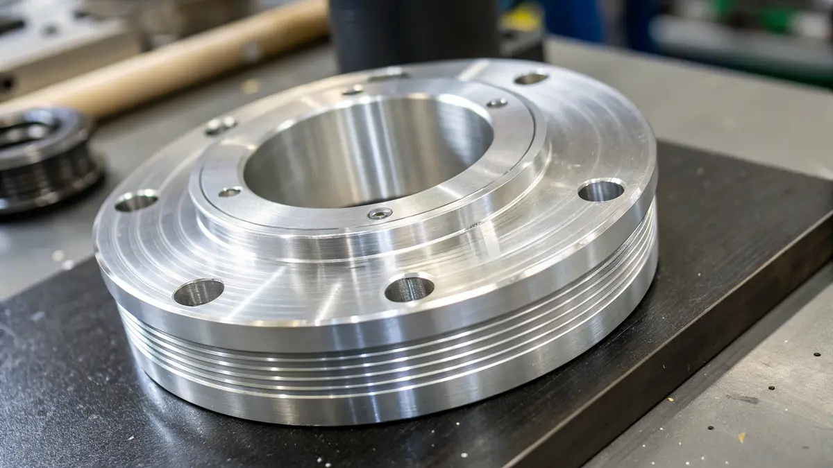
5083 aluminum is a marine-grade aluminum alloy that contains magnesium, manganese, and chromium as its primary alloying elements. It offers exceptional corrosion resistance, particularly in saltwater environments, combined with high strength and excellent weldability, making it ideal for marine and aerospace applications.
Chemical Composition
The effectiveness of 5083 aluminum comes from its carefully balanced composition. Here’s a detailed breakdown of its chemical composition:
| Element | Percentage Range |
|---|---|
| Magnesium | 4.0-4.9% |
| Manganese | 0.4-1.0% |
| Chromium | 0.05-0.25% |
| Silicon | Max 0.4% |
| Iron | Max 0.4% |
| Copper | Max 0.1% |
| Aluminum | Balance |
The high magnesium content1 gives this alloy its distinctive strength-to-weight ratio and corrosion resistance properties.
Key Properties
5083 aluminum stands out for several remarkable characteristics:
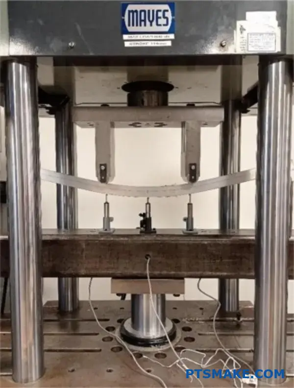
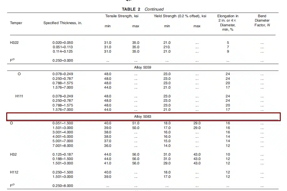
Mechanical Strength
- Tensile Strength: 290 MPa (42,000 psi)
- Yield Strength: 228 MPa (33,000 psi)
- Elongation: 16%
These properties make it significantly stronger than many other aluminum alloys while maintaining good ductility.
Corrosion Resistance
The alloy’s exceptional resistance to seawater and industrial chemicals comes from:
- Formation of a protective oxide layer
- High magnesium content
- Chromium’s stabilizing effect
Weldability
5083 aluminum offers superior weldability characteristics:
- Minimal heat-affected zone
- Strong weld joints
- Excellent resistance to cracking
- Compatible with various welding methods
Industry Applications
Marine Industry
- Ship hulls and superstructures
- Offshore platforms
- Marine equipment
- Storage tanks for cryogenic applications
- Boat fittings and hardware
Aerospace Sector
- Aircraft structural components
- Fuel tanks
- Interior components
- Ground support equipment
Automotive Applications
- Lightweight structural components
- Fuel tanks
- Chassis parts
- Custom performance parts
Processing Considerations
When working with 5083 aluminum, several factors require attention:
Temperature Control
- Optimal forming temperature: 200-300°C
- Avoid excessive heat exposure
- Monitor cooling rates during welding
Surface Treatment
- Anodizing options available
- Chemical conversion coating recommended
- Regular maintenance in marine environments
Machining Guidelines
- Use sharp cutting tools
- Maintain moderate cutting speeds
- Provide adequate cooling during machining
Performance Benefits
The combination of properties in 5083 aluminum delivers several advantages:
Weight Reduction
- 30-50% lighter than steel alternatives
- Improved fuel efficiency in vehicles
- Reduced operating costs
Cost Effectiveness
- Lower maintenance requirements
- Extended service life
- Reduced replacement frequency
Environmental Impact
- 100% recyclable
- Lower carbon footprint
- Sustainable material choice
Market Trends
The demand for 5083 aluminum continues to grow, driven by:
- Increasing marine industry requirements
- Aerospace sector expansion
- Focus on lightweight materials
- Growing emphasis on sustainability
From my experience in precision manufacturing, I’ve observed that 5083 aluminum’s versatility makes it a preferred choice for demanding applications. Its combination of strength, corrosion resistance, and processability offers unique advantages that few other materials can match.
The material’s performance in harsh environments, particularly its resistance to seawater corrosion, has made it indispensable in marine applications. When clients approach me with challenging marine projects, 5083 aluminum often emerges as the optimal solution, especially when weight reduction and durability are crucial factors.
Why Is 5083 Aluminum Challenging to Machine?
Every time I work with 5083 aluminum, I’m reminded of its notorious reputation in the machining world. While many manufacturers are drawn to its excellent corrosion resistance and strength, they often underestimate the complexities it brings to the shop floor. The challenges are so significant that even experienced machinists sometimes struggle to achieve consistent results.
The main challenges in machining 5083 aluminum stem from its high strength, exceptional ductility, and tendency to form built-up edges on cutting tools. These properties make it particularly difficult to achieve precise cuts and maintain consistent surface quality, often requiring specialized tooling and carefully controlled machining parameters.
Understanding the Material Properties
5083 aluminum’s unique composition creates several machining challenges. The material contains significant amounts of magnesium (4.0-4.9%) and manganese (0.4-1.0%), which contribute to its work hardening2 characteristics. I’ve observed that these properties, while excellent for structural applications, create specific challenges during machining operations:
| Property | Impact on Machining |
|---|---|
| High Strength | Requires more cutting force |
| Superior Ductility | Promotes chip wrapping |
| Work Hardening | Increases tool wear |
| Heat Retention | Affects dimensional accuracy |
Built-up Edge Formation
One of the most significant challenges I encounter when machining 5083 aluminum is the formation of built-up edges (BUE). This occurs when the workpiece material adheres to the cutting tool edge, effectively changing the tool geometry and affecting:
- Cutting accuracy
- Surface finish quality
- Tool life
- Dimensional consistency
Heat Management Challenges
The thermal properties of 5083 aluminum present unique challenges during machining operations:
Poor Heat Dissipation
- Creates localized hot spots
- Leads to dimensional instability
- Affects tool life significantly
Thermal Expansion
- Causes dimensional variations
- Requires careful temperature control
- Impacts final part accuracy
Tool Wear Considerations
Through my experience at PTSMAKE, I’ve identified several factors that contribute to accelerated tool wear when machining 5083 aluminum:
Abrasive Properties
- Higher tool wear rates
- Reduced cutting edge life
- Increased tooling costs
Material Adhesion
- Progressive tool deterioration
- Inconsistent cutting performance
- Need for frequent tool changes
Chip Control Issues
The high ductility of 5083 aluminum creates significant chip control challenges:
Long, Stringy Chips
- Risk of entanglement
- Poor surface finish
- Difficult automation
Chip Evacuation
- Required specialized tooling
- Increased coolant pressure
- Modified cutting parameters
Surface Finish Challenges
Achieving and maintaining consistent surface finish quality requires careful attention to:
| Parameter | Consideration |
|---|---|
| Cutting Speed | Must be optimized for minimal BUE |
| Feed Rate | Affects surface roughness |
| Tool Geometry | Requires specific designs |
| Coolant Application | Critical for finish quality |
Productivity Impact
These machining challenges significantly affect production efficiency:
Production Speed
- Slower cutting speeds required
- More frequent tool changes
- Extended setup times
Quality Control
- Increased inspection requirements
- Higher reject rates
- More frequent process adjustments
Cost Implications
- Higher tooling expenses
- Extended machining times
- Increased labor costs
Process Optimization Requirements
To successfully machine 5083 aluminum, I’ve found these process optimizations essential:
Cutting Parameters
- Carefully selected speeds and feeds
- Optimized depth of cut
- Balanced cutting forces
Tool Selection
- Specialized coating requirements
- Specific geometry designs
- Regular tool condition monitoring
Cooling Strategy
- High-pressure coolant delivery
- Optimal coolant concentration
- Consistent temperature control
The challenges of machining 5083 aluminum require a comprehensive understanding of both the material properties and machining dynamics. Success depends on careful attention to multiple factors, including tool selection, cutting parameters, and process controls. While these challenges can be overcome, they require significant expertise and careful planning to achieve consistent, high-quality results.
What Are the Best Tools for Machining 5083 Aluminum?
Choosing incorrect cutting tools for 5083 aluminum machining can lead to poor surface finish, dimensional inaccuracies, and excessive tool wear. I’ve seen many manufacturers struggle with built-up edge formation and inadequate chip evacuation, resulting in costly production delays and material waste.
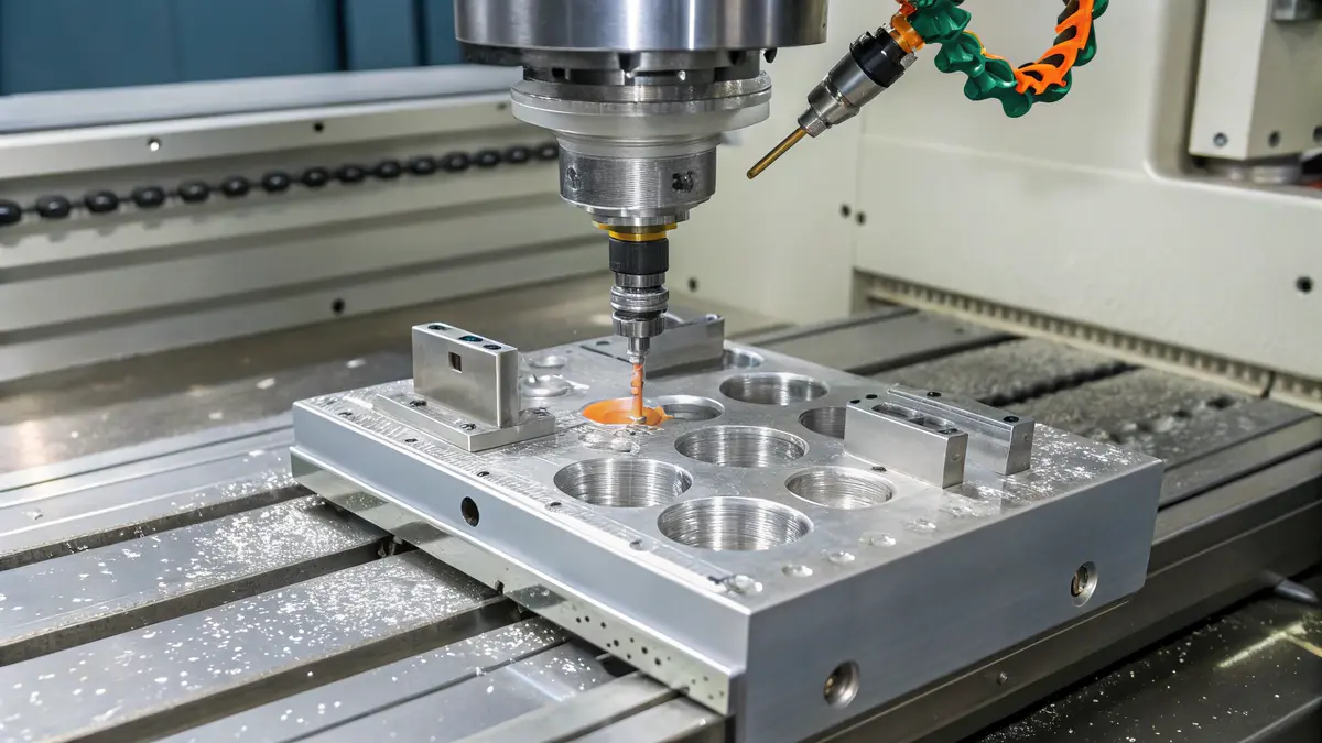
The best tools for machining 5083 aluminum are carbide end mills with 2-3 flutes, diamond-coated cutting tools, and specially designed aluminum-grade inserts. These tools, combined with proper coating and geometry, ensure optimal cutting performance and surface finish.
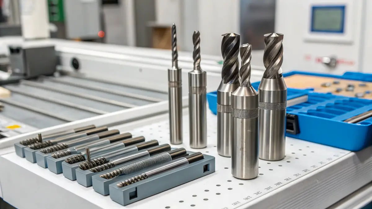
Carbide Cutting Tools
Carbide tools remain the primary choice for machining 5083 aluminum due to their excellent balance of hardness and toughness. When selecting carbide tools, consider these key factors:
Substrate Grade
- Fine-grain carbide provides better wear resistance
- Medium-grain carbide offers improved toughness
- Micro-grain carbide ensures superior edge stability
Coating Selection
The right coating can significantly impact tool performance. Here’s a comparison of common coatings:
| Coating Type | Advantages | Best Applications |
|---|---|---|
| TiAlN | High heat resistance | High-speed machining |
| ZrN | Low friction coefficient | Finish cutting |
| Diamond | Superior wear resistance | Heavy roughing |
| Uncoated | Sharp cutting edges | Light finishing |
End Mill Specifications
The helix angle3 and flute count are crucial factors in end mill selection:
Flute Configuration
- 2-3 flutes: Optimal for most aluminum operations
- Single flute: Excellent for deep pocket milling
- 4+ flutes: Reserved for finishing operations
Geometry Features
- High rake angles (15-20 degrees)
- Large chip gullets
- Polished flutes for better chip evacuation
Insert Selection and Design
Choosing the right inserts can make a significant difference in machining outcomes:
Insert Geometry
- Sharp positive rake angles
- Large chip breakers
- Polished rake faces
Grade Selection
Table of recommended insert grades:
| Application | Grade Type | Coating |
|---|---|---|
| Roughing | K20-K30 | PVD |
| Semi-finishing | K10-K20 | TiB2 |
| Finishing | K01-K10 | Uncoated |
Coolant Considerations
Proper coolant selection and application significantly impact tool performance:
Coolant Types
- High-pressure coolant systems
- Minimum quantity lubrication (MQL)
- Flood coolant with special aluminum additives
Application Methods
- Through-tool cooling
- External flood cooling
- Air blast cooling for chip evacuation
Tool Life Management
To maximize tool life when machining 5083 aluminum:
Cutting Parameters
- Maintain recommended surface speeds
- Use appropriate feed rates
- Monitor cutting forces
Wear Monitoring
- Regular tool inspection
- Predictive maintenance
- Wear pattern analysis
Specialized Tools for Complex Features
For specific machining operations:
Threading Tools
- Thread mills with aluminum-specific geometries
- Single-point threading tools
- Thread forming taps
Drilling Solutions
- Specialized aluminum drill geometries
- Step drills for larger holes
- Combination tools for complex features
Reaming Tools
- Multi-flute reamers
- Adjustable reamers
- Single-flute reamers
The success in machining 5083 aluminum largely depends on selecting the right combination of tools and maintaining proper cutting conditions. By understanding these tool selection criteria and implementing them correctly, manufacturers can achieve optimal results in terms of surface finish, dimensional accuracy, and production efficiency.
This comprehensive approach to tool selection ensures that each machining operation is performed with the most suitable tool, resulting in improved productivity and reduced manufacturing costs. Remember to regularly evaluate tool performance and adjust selections based on specific application requirements and operational feedback.
What Are the Recommended Cutting Speeds and Feeds?
Setting incorrect cutting parameters for 5083 aluminum can lead to poor surface finish, excessive tool wear, and even part rejection. Many machinists struggle to find the right balance, often relying on trial and error which wastes time and materials.
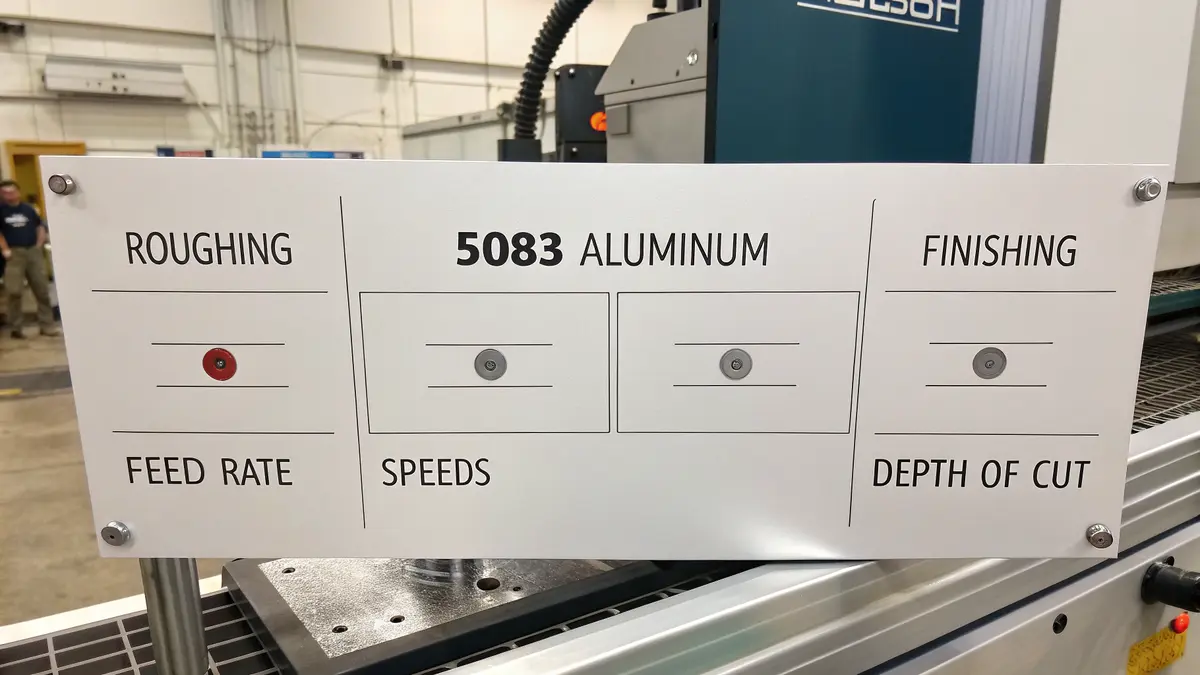
For 5083 aluminum, I recommend a cutting speed of 1000-1500 SFM for roughing and 1500-2000 SFM for finishing operations. The feed rate should be 0.004-0.012 inches per revolution, with a depth of cut ranging from 0.02-0.25 inches depending on the operation.
Understanding Basic Cutting Parameters
The foundation of successful CNC machining lies in understanding and properly setting your cutting parameters. When machining 5083 aluminum, three key factors work together to determine your results: cutting speed, feed rate, and depth of cut. These parameters significantly impact your material removal rate4 and overall machining efficiency.
Let me break down each parameter and provide specific recommendations based on my experience:
Recommended Cutting Speeds
For 5083 aluminum, I’ve found these cutting speeds work best:
| Operation Type | Speed (SFM) | Notes |
|---|---|---|
| Roughing | 1000-1500 | Higher speeds possible with proper cooling |
| Finishing | 1500-2000 | Produces excellent surface finish |
| Threading | 800-1000 | Lower speeds prevent thread damage |
| Drilling | 300-500 | Prevents drill wandering |
Feed Rates and Their Impact
Feed rates must be carefully selected to complement your cutting speeds:
| Operation | Feed (IPR) | Benefits |
|---|---|---|
| Roughing | 0.008-0.012 | Maximum material removal |
| Finishing | 0.004-0.008 | Superior surface finish |
| Threading | 0.002-0.004 | Clean thread formation |
| Drilling | 0.006-0.010 | Efficient chip evacuation |
Depth of Cut Considerations
The depth of cut varies based on your machining phase:
| Operation Stage | Depth (inches) | Purpose |
|---|---|---|
| Initial Roughing | 0.15-0.25 | Bulk material removal |
| Secondary Roughing | 0.05-0.15 | Prepare for finishing |
| Finishing | 0.02-0.05 | Achieve final dimensions |
Spindle Speed Calculations
To determine the correct spindle speed (RPM), use this formula:
RPM = (CS × 12) / (π × D)
Where:
- CS = Cutting speed in surface feet per minute (SFM)
- D = Tool or workpiece diameter in inches
- π = 3.14159
Cooling and Lubrication Requirements
Proper cooling is crucial when machining 5083 aluminum:
| Cooling Method | Application | Benefits |
|---|---|---|
| Flood Coolant | General Purpose | Good heat dissipation |
| Through-Tool Coolant | Deep Holes | Superior chip evacuation |
| Mist Cooling | Light Cuts | Adequate for finishing |
Tool Selection and Wear Considerations
The right tool selection impacts your cutting parameters:
| Tool Type | Recommended Coating | Application |
|---|---|---|
| Carbide | TiAlN | General purpose |
| HSS | Uncoated | Economic choice |
| Diamond | None | Mirror finish |
Quality Control Measures
Monitor these aspects during machining:
- Surface roughness
- Dimensional accuracy
- Tool wear patterns
- Chip formation
- Temperature stability
By following these guidelines, you can achieve optimal results when machining 5083 aluminum. Remember that these parameters may need adjustment based on your specific machine capabilities and project requirements. Start with conservative values and adjust gradually while monitoring results.
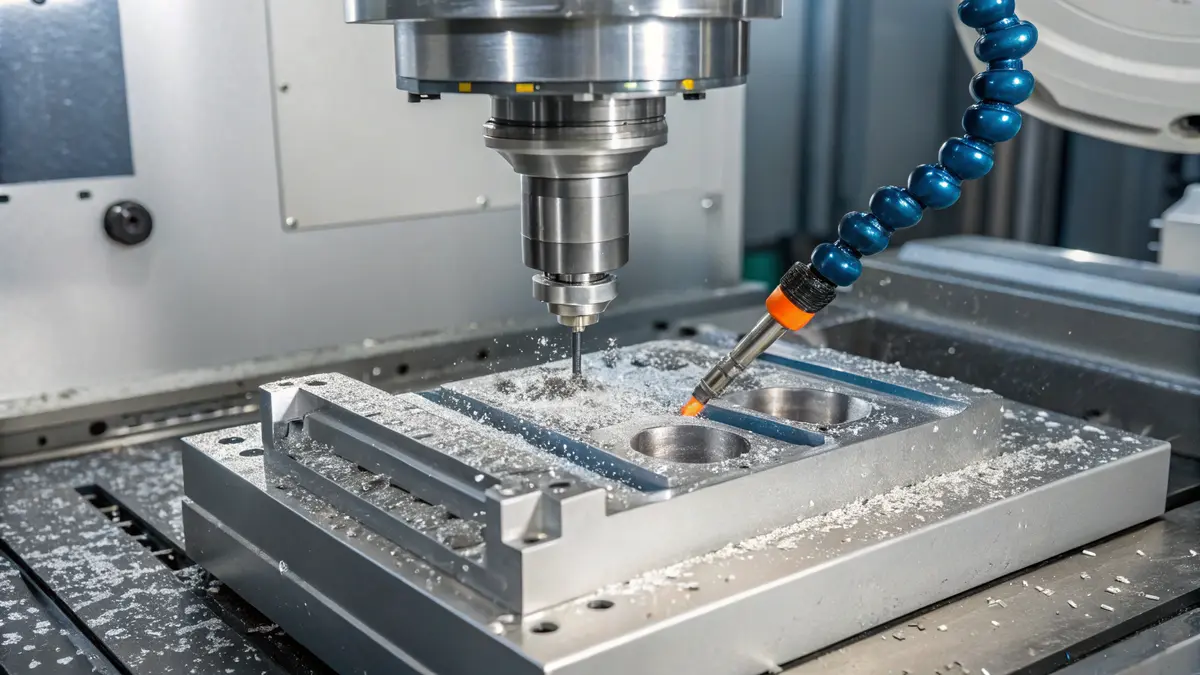
How to Improve Chip Control?
When machining 5083 aluminum, uncontrolled chips can quickly turn a precise operation into a costly disaster. I’ve witnessed countless cases where poor chip management led to scrapped parts, damaged tools, and extended downtime. These issues not only impact production efficiency but also significantly increase operational costs.
Effective chip control in aluminum machining requires a comprehensive approach combining proper tool selection, cutting parameters, and cooling strategies. By implementing the right techniques, you can achieve better surface finish, longer tool life, and improved productivity.
The Foundation of Effective Chip Control
Proper chip control starts with understanding how chips form during the machining process. The [chip formation mechanism]5 directly influences the cutting process efficiency and part quality. I recommend focusing on these key aspects:
- Cutting speed optimization
- Feed rate adjustment
- Depth of cut selection
- Tool geometry configuration
Optimizing Cutting Parameters
The relationship between cutting parameters and chip formation is crucial. Here’s a detailed breakdown of recommended parameters for 5083 aluminum:
| Parameter | Recommended Range | Impact on Chip Control |
|---|---|---|
| Cutting Speed | 800-1200 sfm | Controls chip temperature and formation |
| Feed Rate | 0.004-0.012 ipr | Affects chip thickness and breaking |
| Depth of Cut | 0.020-0.100 in | Influences chip size and evacuation |
High-Pressure Coolant Implementation
High-pressure coolant systems have revolutionized chip control in aluminum machining. I recommend implementing these specific strategies:
- Use coolant pressure between 800-1000 PSI for optimal chip breaking
- Position coolant nozzles directly at the cutting zone
- Maintain consistent coolant flow throughout the operation
- Regular monitoring of coolant concentration and cleanliness
Advanced Tool Geometries
Selecting the right tool geometry is essential for effective chip control. My experience has shown these features to be most effective:
- Positive rake angles (10-15 degrees)
- Sharp cutting edges
- Polished flutes for improved chip evacuation
- Specialized chip breaker designs
Mist and Air Cooling Solutions
In certain applications, traditional flood coolant might not be the best option. Alternative cooling methods include:
Minimum Quantity Lubrication (MQL)
- Reduces environmental impact
- Improves chip evacuation in deep pockets
- Ideal for high-speed machining operations
Air-blast cooling
- Perfect for light cuts and finishing operations
- Prevents chip re-cutting
- Reduces cleanup time
Process Monitoring and Adjustment
Continuous monitoring ensures optimal chip control:
- Visual inspection of chip formation
- Regular tool wear assessment
- Adjustment of parameters based on:
- Material variations
- Tool condition
- Part geometry requirements
Best Practices for Implementation
To achieve optimal results, follow these guidelines:
Pre-operation planning
- Review material properties
- Select appropriate tooling
- Set up proper coolant delivery
During operation
- Monitor chip formation
- Listen for unusual sounds
- Check surface finish quality
Post-operation evaluation
- Analyze tool wear patterns
- Document successful parameters
- Review areas for improvement
Troubleshooting Common Issues
When chip control problems arise, consider these solutions:
Long, stringy chips
- Increase feed rate
- Adjust chip breaker geometry
- Review coolant pressure
Built-up edge formation
- Increase cutting speed
- Check coolant concentration
- Modify tool coating selection
Poor surface finish
- Verify tool geometry
- Adjust cutting parameters
- Evaluate coolant delivery
Following these comprehensive strategies has consistently helped our clients at PTSMAKE achieve better machining results with 5083 aluminum. Remember that successful chip control is not about following a single solution but rather implementing a combination of techniques tailored to your specific application.
What Are the Best Strategies to Reduce Tool Wear?
Machining 5083 aluminum presents a significant challenge in maintaining tool life. The material’s high strength and tendency to form built-up edges can quickly deteriorate cutting tools, leading to increased production costs and quality issues. Tool replacement downtime and inconsistent surface finishes are frustrating problems that many manufacturers face.
To reduce tool wear when machining 5083 aluminum, implement optimized cutting parameters, use appropriate cooling strategies, and select specialized cutting tools. Key strategies include using coated carbide or PCD tools, maintaining proper feed rates, and applying sufficient lubrication to prevent built-up edges.
Understanding Cutting Parameters
The foundation of tool wear reduction starts with proper cutting parameters. When machining 5083 aluminum, the cutting speed6 plays a crucial role in tool life. I’ve found that maintaining these parameters helps achieve optimal results:
| Parameter | Recommended Range | Impact on Tool Life |
|---|---|---|
| Cutting Speed | 300-500 m/min | Reduces heat generation |
| Feed Rate | 0.1-0.3 mm/rev | Prevents chip buildup |
| Depth of Cut | 1-3 mm | Controls cutting forces |
Cooling and Lubrication Strategies
Effective cooling is essential for extending tool life. I recommend these approaches:
- High-pressure coolant delivery
- Minimum Quantity Lubrication (MQL)
- Through-tool cooling systems
These methods help prevent aluminum adhesion and reduce thermal stress on cutting tools.
Tool Selection and Coating Technology
The right tool selection significantly impacts wear resistance. Here’s what works best:
Coated Carbide Tools
- TiAlN coating for improved heat resistance
- Multi-layer coatings for better wear protection
- Smooth surface finish to prevent material adhesion
PCD Tools
- Superior wear resistance
- Excellent for high-volume production
- Better thermal conductivity
Cutting Edge Preparation
Tool geometry plays a vital role in wear reduction:
Edge Rounding
- Strengthens cutting edge
- Reduces chipping risk
- Improves coating adhesion
Surface Treatment
- Micro-blasting for enhanced coating adhesion
- Polishing to reduce friction
Operational Best Practices
To maximize tool life, I always emphasize these operational guidelines:
Regular Tool Inspection
- Monitor wear patterns
- Check for coating deterioration
- Measure cutting edge condition
Proper Tool Storage
- Climate-controlled environment
- Protection from physical damage
- Regular cleaning and maintenance
Built-up Edge Prevention
Managing built-up edge formation requires attention to:
Surface Speed Control
- Maintain recommended cutting speeds
- Adjust based on material condition
- Monitor tool temperature
Chip Management
- Ensure proper chip evacuation
- Use appropriate chip breakers
- Maintain consistent feed rates
Production Environment Considerations
The manufacturing environment impacts tool wear:
Temperature Control
- Maintain stable ambient temperature
- Monitor coolant temperature
- Control workpiece temperature
Machine Maintenance
- Regular spindle alignment checks
- Vibration monitoring
- Coolant system maintenance
Cost-Effective Implementation
Implementing these strategies requires balancing costs:
Initial Investment
- High-quality tools
- Coating technology
- Cooling systems
Long-term Benefits
- Reduced tool changes
- Improved part quality
- Higher productivity
By following these comprehensive strategies, I’ve consistently achieved significant improvements in tool life when machining 5083 aluminum. The key is maintaining a systematic approach to implementation and regularly monitoring results for optimization.
How to Achieve a High-Quality Surface Finish?
Achieving the perfect surface finish on 5083 aluminum parts can be incredibly challenging. Many manufacturers struggle with inconsistent results, leading to rejected parts and costly rework. The combination of tool wear, improper speeds, and inadequate cooling can quickly turn a promising project into a manufacturing nightmare.
The key to achieving excellent surface finish on 5083 aluminum lies in optimizing machining parameters, selecting appropriate tooling, and implementing proper post-processing techniques. This comprehensive approach ensures consistent quality while maintaining production efficiency.
Understanding Tool Geometry Impact
The geometry of cutting tools plays a crucial role in surface finish quality. I’ve found that using tools with positive rake angles between 5-15 degrees provides the best results for 5083 aluminum. The rake angle7 significantly affects chip formation and cutting forces.
Here’s a detailed breakdown of optimal tool characteristics:
| Tool Parameter | Recommended Range | Impact on Surface Finish |
|---|---|---|
| Rake Angle | 5-15 degrees | Reduces cutting forces and improves chip evacuation |
| Relief Angle | 10-12 degrees | Prevents tool rubbing and heat generation |
| Nose Radius | 0.2-0.8 mm | Larger radius for smoother finish |
| Edge Preparation | Sharp to light hone | Reduces built-up edge formation |
Optimizing Feed Rate and Speed
Feed rate and cutting speed optimization are essential for achieving superior surface finish. Based on my experience with 5083 aluminum, I recommend:
- Cutting Speed: 1000-1500 surface feet per minute (SFM)
- Feed Rate: 0.003-0.007 inches per revolution (IPR)
- Depth of Cut: 0.020-0.040 inches for finishing passes
These parameters should be adjusted based on specific tool geometry and machine capabilities.
Cooling and Lubrication Strategies
Proper cooling and lubrication are critical for maintaining consistent surface quality. I recommend:
- High-pressure coolant delivery (minimum 800 PSI)
- Oil-based cutting fluids with aluminum-specific additives
- Through-tool coolant capability when possible
- Regular coolant concentration monitoring (maintaining 6-8%)
Post-Machining Treatments
To enhance surface quality further, several post-machining treatments can be employed:
Mechanical Polishing
- Progressive grit sequence (400-2000)
- Automated polishing systems for consistency
- Buffing compounds specific to aluminum
Anodizing Considerations
- Type II anodizing for general applications
- Type III for enhanced wear resistance
- Pre-anodizing surface preparation critical for finish quality
Quality Control Measures
Implementing proper quality control measures ensures consistent surface finish:
Regular Surface Roughness Testing
- Ra measurements below 32 microinches
- Documentation of results
- Statistical process control implementation
Visual Inspection Protocol
- Trained inspectors
- Proper lighting conditions
- Standardized acceptance criteria
Common Challenges and Solutions
Several challenges often arise when machining 5083 aluminum:
Built-up Edge Formation
- Solution: Increase cutting speed
- Use appropriate cutting fluid
- Maintain sharp cutting edges
Chatter Marks
- Solution: Verify tool holder balance
- Check machine vibration
- Adjust cutting parameters
Poor Chip Evacuation
- Solution: Optimize coolant pressure
- Use chip breakers
- Implement proper programming strategies
Process Documentation and Control
Maintaining consistent surface finish requires proper documentation:
Process Parameters
- Tool specifications
- Cutting parameters
- Coolant information
Quality Requirements
- Surface roughness specifications
- Visual standards
- Measurement methods
Maintenance Schedule
- Tool wear monitoring
- Machine calibration
- Coolant system maintenance
This comprehensive approach to surface finish optimization has helped us achieve consistently high-quality results on 5083 aluminum components. By carefully controlling each aspect of the machining process and implementing proper post-processing techniques, we can meet the most demanding surface finish requirements while maintaining production efficiency.
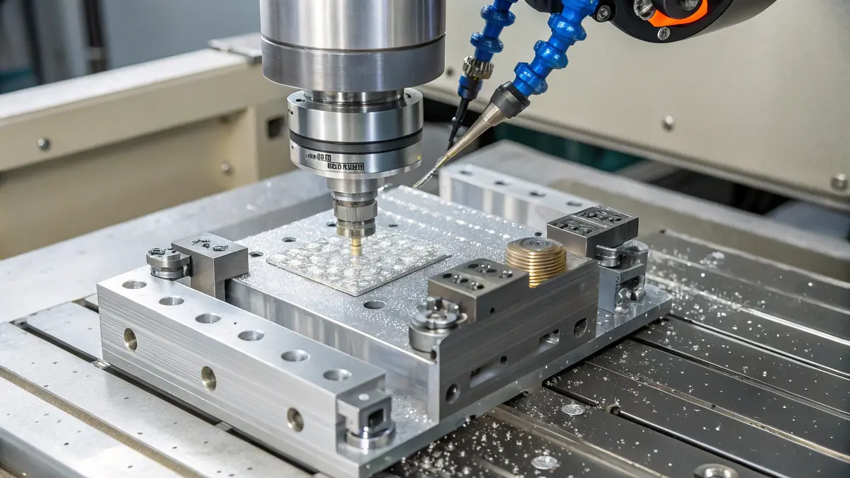
What Cooling and Lubrication Techniques Work Best?
Machining 5083 aluminum without proper cooling can lead to devastating results. I’ve witnessed countless projects fail due to excessive heat buildup, resulting in poor surface finish, dimensional inaccuracies, and premature tool wear. The consequences of inadequate cooling can turn a simple machining job into a costly nightmare.
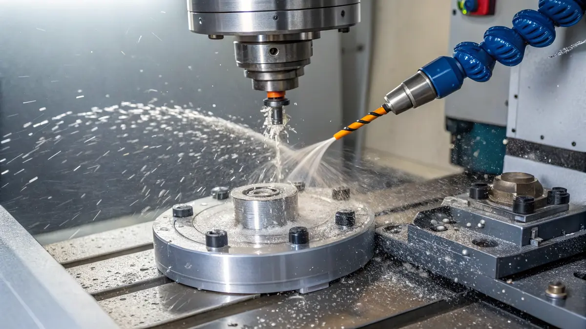
The most effective cooling method for 5083 aluminum machining is flood cooling with water-soluble coolants, maintaining a concentration of 6-8%. This approach provides optimal heat dissipation, reduces tool wear, and ensures consistent surface quality while preventing built-up edge formation.
Understanding Cooling Methods
Modern CNC machining demands precise temperature control during the cutting process. The thermal conductivity8 of 5083 aluminum makes it particularly sensitive to heat-related issues. Here’s my detailed breakdown of the main cooling methods:
Flood Cooling
- Provides continuous coolant flow
- Excellent heat dissipation
- Superior chip evacuation
- Ideal for high-speed operations
Mist Cooling
- Reduces coolant consumption
- Suitable for lighter cuts
- Environmentally friendly option
- Better visibility during machining
Air Cooling
- Minimal setup required
- Clean operation
- Cost-effective solution
- Limited cooling capacity
Coolant Types and Their Performance
My experience with different coolant types has shown significant variations in performance. Here’s a comprehensive comparison:
| Coolant Type | Heat Dissipation | Tool Life | Surface Finish | Cost Effectiveness |
|---|---|---|---|---|
| Synthetic | Excellent | High | Superior | Moderate |
| Semi-synthetic | Very Good | Good | Very Good | High |
| Water-soluble | Excellent | Very High | Excellent | Very High |
| Straight Oil | Good | Moderate | Good | Low |
Optimizing Coolant Application
The effectiveness of cooling solutions depends heavily on proper application techniques. I recommend focusing on these key aspects:
Coolant Pressure and Volume
- High-pressure delivery (500-1000 PSI) for deep pockets
- Consistent flow rate maintenance
- Multiple nozzle positioning for complex geometries
- Regular pressure monitoring
Concentration Management
- Weekly concentration checks
- Maintain 6-8% concentration for water-soluble coolants
- Regular pH monitoring (ideal range: 8.5-9.5)
- Documented maintenance schedule
Advanced Cooling Strategies
Innovation in cooling technology has introduced several advanced methods that I’ve implemented successfully:
Through-Tool Cooling
- Direct coolant delivery to cutting edge
- Reduced heat buildup
- Improved chip evacuation
- Extended tool life
Cryogenic Cooling
- Extreme temperature reduction
- Minimal environmental impact
- Enhanced surface finish
- Reduced thermal deformation
Maintenance and Monitoring
Proper maintenance ensures optimal cooling performance:
- Daily coolant level checks
- Weekly concentration testing
- Monthly system cleaning
- Quarterly complete fluid replacement
Environmental Considerations
Modern manufacturing demands environmentally conscious choices:
- Biodegradable coolant options
- Recycling and filtration systems
- Proper disposal protocols
- VOC emission reduction
Safety Protocols
Safety remains paramount when handling cooling systems:
- Regular bacterial testing
- Proper PPE requirements
- Spill containment procedures
- Emergency response planning
Future Trends
The cooling technology landscape continues to evolve:
- IoT-enabled monitoring systems
- AI-driven coolant management
- Sustainable coolant formulations
- Hybrid cooling solutions
Cost Implications
Effective cooling strategy implementation affects the bottom line:
- Initial setup costs
- Ongoing maintenance expenses
- Long-term tool life benefits
- Production efficiency gains
The choice of cooling and lubrication technique significantly impacts machining success with 5083 aluminum. Based on our extensive testing and real-world applications, flood cooling with water-soluble coolants provides the most reliable and efficient solution for most applications. However, specific project requirements might necessitate alternative approaches, making it crucial to understand all available options.
How to Prevent Workpiece Deformation?
Workpiece deformation in 5083 aluminum machining has become a persistent challenge in precision manufacturing. I’ve seen countless projects derailed by unexpected warping and distortion, causing costly rework and production delays. The problem becomes even more critical when dealing with high-precision components where every micron matters.
To prevent workpiece deformation in 5083 aluminum, implement proper stress relief procedures, optimize clamping strategies, and carefully plan machining sequences. Additionally, controlling cutting parameters and using appropriate fixtures can significantly reduce distortion risks.
Understanding Residual Stress in 5083 Aluminum
The root cause of deformation often lies in residual stress9 within the material. I’ve found that 5083 aluminum is particularly susceptible to stress-induced deformation due to its specific alloy composition. Here’s what typically causes residual stress:
- Manufacturing processes (rolling, forming)
- Temperature variations during material processing
- Previous machining operations
- Improper storage conditions
Pre-Machining Stress Relief Techniques
I’ve developed a systematic approach to stress relief that has proven effective in our operations:
| Treatment Method | Temperature Range | Duration | Benefits |
|---|---|---|---|
| Thermal Stress Relief | 230-260°C | 1-2 hours | Uniform stress distribution |
| Vibratory Stress Relief | Room temp | 20-30 minutes | Non-thermal alternative |
| Natural Aging | Room temp | 24-48 hours | Cost-effective solution |
Optimizing Clamping Strategies
The way we clamp workpieces significantly impacts deformation. I recommend these proven techniques:
Distributed Clamping Force
- Use multiple clamping points
- Apply consistent torque values
- Monitor clamping pressure regularly
Strategic Fixture Design
- Support critical features
- Allow for thermal expansion
- Minimize contact area where possible
Smart Machining Sequence Planning
Based on my experience, proper sequencing is crucial:
Rough Machining Phase
- Remove material symmetrically
- Maintain balanced stress distribution
- Leave adequate stock for finishing
Intermediate Stress Relief
- Allow parts to stabilize between operations
- Check for any preliminary deformation
- Make necessary adjustments
Finish Machining
- Use light cuts
- Maintain consistent depth of cut
- Monitor temperature carefully
Cutting Parameter Optimization
I’ve found these parameters work best for minimizing deformation:
| Parameter | Rough Machining | Finish Machining |
|---|---|---|
| Cutting Speed | 300-400 m/min | 400-500 m/min |
| Feed Rate | 0.15-0.25 mm/tooth | 0.05-0.15 mm/tooth |
| Depth of Cut | 2-4 mm | 0.2-0.5 mm |
| Coolant Flow | High | Moderate |
Temperature Control Strategies
Temperature management is critical for dimensional stability:
Coolant Management
- Use high-pressure coolant systems
- Maintain consistent coolant temperature
- Ensure adequate flow rate
Cutting Zone Temperature
- Monitor tool temperature
- Implement proper cooling breaks
- Use appropriate cutting speeds
Quality Control and Verification
To ensure success, I always implement these verification steps:
In-Process Measurements
- Regular dimensional checks
- Stress pattern monitoring
- Temperature tracking
Final Inspection
- CMM verification
- Flatness measurements
- Surface finish analysis
Environmental Considerations
The shop environment plays a crucial role:
Temperature Control
- Maintain stable ambient temperature
- Avoid direct sunlight exposure
- Control air circulation
Storage Practices
- Proper material storage
- Protected from environmental factors
- Regular stock rotation
Through implementing these comprehensive strategies, we’ve achieved consistent success in preventing workpiece deformation in 5083 aluminum machining. The key lies in understanding that deformation prevention is not a single-step process but rather a systematic approach that begins with material selection and continues through final inspection.
Remember that each project may require slight adjustments to these guidelines based on specific requirements and conditions. Always start with a thorough understanding of your particular application and adjust these recommendations accordingly.
What Are Common Quality Control Methods?
Quality control in 5083 aluminum machining can be a major headache for manufacturers. Without proper inspection methods, even minor deviations can lead to part rejection, production delays, and significant financial losses. I’ve seen many manufacturers struggle when their quality control processes aren’t robust enough.
Quality control for 5083 aluminum machining involves multiple inspection techniques including CMM measurements, surface analysis, and visual checks. These methods work together with process monitoring and tolerance verification to ensure parts consistently meet specifications.
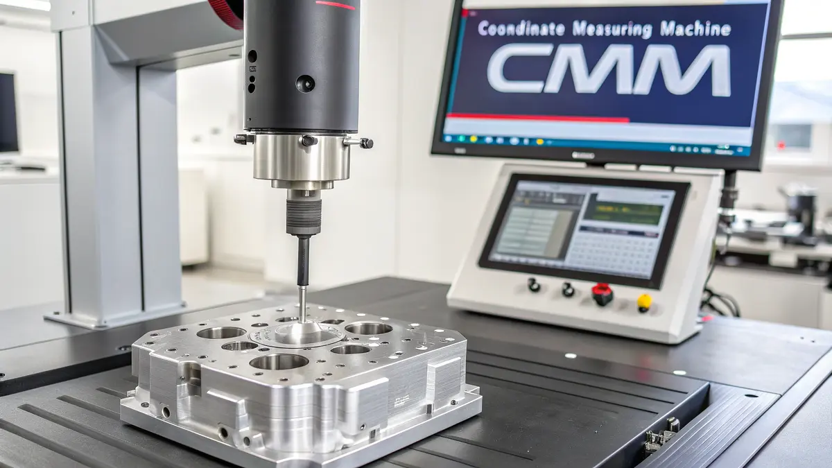
Coordinate Measuring Machine (CMM) Inspection
CMM inspection is the backbone of our quality control process at PTSMAKE. This advanced measurement system uses a probe to collect precise dimensional data from machined parts. The metrology10 capabilities of CMM machines allow us to:
- Measure complex geometries with accuracy up to 0.001mm
- Compare actual dimensions against CAD models
- Generate detailed inspection reports
- Identify deviations early in the production process
I ensure our team performs CMM inspections at key production stages:
- First article inspection
- In-process checks
- Final verification
Surface Roughness Analysis
Surface quality is crucial for 5083 aluminum parts. We use both contact and non-contact methods to measure surface roughness:
| Method | Applications | Advantages |
|---|---|---|
| Profilometer | Flat surfaces, Simple geometries | High accuracy, Quantitative data |
| Optical scanner | Complex geometries, Deep features | Non-contact, Fast measurement |
| Vision systems | Surface defects, Pattern recognition | Real-time inspection, Large areas |
Visual Inspection Protocols
While advanced measurement tools are essential, trained visual inspection remains valuable. Our inspectors check for:
Surface defects
- Scratches
- Dents
- Tool marks
Material consistency
- Color uniformity
- Surface finish
- Material integrity
Workmanship quality
- Edge quality
- Burr removal
- Overall appearance
Process Monitoring Systems
Real-time monitoring helps maintain quality throughout production:
Machine parameters monitoring
- Spindle speed
- Feed rates
- Tool wear
- Temperature
Statistical Process Control (SPC)
- Control charts
- Trend analysis
- Process capability studies
Tolerance Verification Methods
We implement a multi-level approach to tolerance verification:
Pre-machining checks
- Material certification
- Stock dimensions
- Setup verification
In-process verification
- Critical dimension measurements
- Geometric tolerances
- Surface finish checks
Final inspection
- Full dimensional verification
- Functional testing
- Documentation review
Documentation and Reporting
Quality control documentation is crucial for traceability:
- Inspection reports
- Material certificates
- Process parameters
- Non-conformance records
- Corrective actions
I’ve implemented a digital documentation system that allows quick access to quality records and helps identify trends or potential issues before they become problems.
Quality Management System Integration
Our quality control methods are part of a larger quality management system:
Standard Operating Procedures (SOPs)
- Detailed work instructions
- Inspection procedures
- Calibration requirements
Training Programs
- Inspector certification
- Equipment operation
- Quality awareness
Continuous Improvement
- Regular audits
- Performance metrics
- Process optimization
Equipment Calibration and Maintenance
Regular calibration ensures measurement accuracy:
- Annual calibration of CMM machines
- Monthly verification of measuring tools
- Daily checks of basic instruments
- Preventive maintenance schedules
This comprehensive approach to quality control helps us maintain consistent quality in 5083 aluminum machining. By combining advanced measurement technology with proven inspection methods and careful documentation, we can ensure that parts meet specifications consistently.
Understand magnesium’s role in enhancing strength and resistance, crucial for selecting the right aluminum alloy. ↩
Learn how work hardening affects machining and ways to overcome its challenges. ↩
Learn how helix angle impacts chip formation and improves machining performance. ↩
Learn how to optimize machining efficiency by adjusting material removal rate parameters. ↩
Understand chip formation for enhanced machining efficiency and improved part quality. ↩
Learn about cutting speed to optimize tool life and enhance machining efficiency. ↩
Learn how rake angle affects chip formation and cutting forces for better surface finish. ↩
Understand aluminum’s heat sensitivity for effective cooling strategies in machining. ↩
Learn about residual stress effects on machining and how to mitigate deformation. ↩
Learn about metrology to enhance measurement accuracy and improve manufacturing quality control. ↩