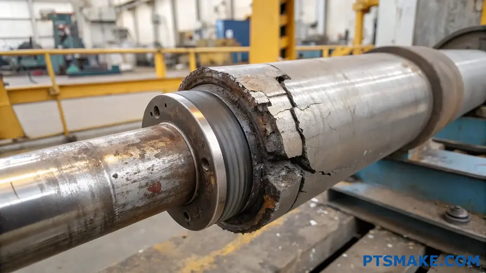
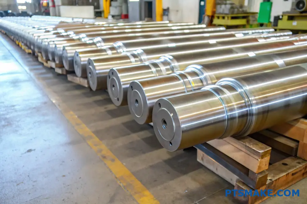
A broken pump shaft can bring your entire operation to a halt without warning. I’ve witnessed countless manufacturing lines shut down because of this seemingly small component failure, causing thousands of dollars in losses and missed deadlines.
A pump shaft typically breaks due to misalignment, excessive vibration, material fatigue, or overload conditions. These issues often develop gradually and can be prevented through regular maintenance, proper installation, and monitoring operating conditions.
I understand how frustrating pump shaft failures can be – they’re not just about replacing a part, but also about lost production time and potential damage to other components. Let me share my insights on the specific causes and how you can detect them early to prevent catastrophic failures.
Why Is The Pump Shaft Broken?
Have you ever faced a sudden pump failure due to a broken shaft? It’s not just about the immediate breakdown – it’s the production delays, the unexpected costs, and the stress of finding quick solutions. When a pump shaft breaks, entire production lines can grind to a halt, causing ripple effects throughout your operations.
A pump shaft typically breaks due to misalignment, excessive vibration, material fatigue, or improper maintenance. Understanding these root causes is crucial for preventing future failures and ensuring reliable pump operation in industrial settings.
Common Causes of Pump Shaft Failure
Material Fatigue and Stress
Material fatigue is often the primary culprit in shaft failures. When a pump operates under cyclic loading1, the shaft material gradually weakens. I’ve analyzed numerous cases where seemingly minor stress concentrations led to catastrophic failures. The key factors contributing to material fatigue include:
- Repetitive stress cycles
- Environmental conditions
- Operating temperature variations
- Chemical exposure
Misalignment Issues
Shaft misalignment remains one of the most prevalent causes of failure. Based on my experience at PTSMAKE, proper alignment is crucial for long-term reliability. Here’s what we typically observe:
| Misalignment Type | Common Symptoms | Potential Consequences |
|---|---|---|
| Angular | Excessive vibration | Premature bearing wear |
| Parallel | Unusual noise | Seal failure |
| Combined | High temperature | Shaft fracture |
Improper Installation and Maintenance
Poor installation practices often lead to premature shaft failure. The following aspects require careful attention:
- Foundation preparation
- Coupling alignment
- Bearing installation
- Lubrication systems
Impact of Operating Conditions
Speed and Load Variations
Operating conditions significantly influence shaft life. We must consider:
- Starting and stopping frequencies
- Load variations
- Operating speed ranges
- Emergency shutdown impacts
Environmental Factors
Environmental conditions play a crucial role in shaft longevity:
| Environmental Factor | Impact on Shaft | Prevention Measures |
|---|---|---|
| Humidity | Corrosion | Protective coatings |
| Temperature | Thermal stress | Proper ventilation |
| Chemical exposure | Material degradation | Material selection |
| Dust/particles | Wear | Sealed systems |
Design Considerations
Material Selection
Proper material selection is critical for shaft reliability. At PTSMAKE, we carefully evaluate:
- Material strength requirements
- Corrosion resistance needs
- Cost-effectiveness
- Availability of materials
Dimensional Factors
Key dimensional considerations include:
- Shaft diameter
- Length-to-diameter ratio
- Critical speed calculations
- Stress concentration factors
Preventive Measures
Regular Inspection Protocols
Implementing regular inspection protocols helps identify potential issues before failure occurs:
- Visual inspections
- Vibration analysis
- Temperature monitoring
- Oil analysis
Maintenance Best Practices
| Maintenance Task | Frequency | Purpose |
|---|---|---|
| Alignment check | Monthly | Prevent misalignment |
| Bearing inspection | Quarterly | Detect wear |
| Lubrication | Weekly | Reduce friction |
| Vibration monitoring | Continuous | Early warning |
Modern Monitoring Solutions
Advanced monitoring technologies help prevent shaft failures:
- Real-time vibration monitoring
- Temperature sensors
- Digital alignment tools
- Predictive maintenance systems
Over the years, I’ve seen how proper maintenance and monitoring can significantly extend pump shaft life. At PTSMAKE, we emphasize the importance of preventive maintenance and proper installation procedures. Our engineering team regularly conducts failure analysis to help clients prevent similar issues in their operations.
Remember, a broken pump shaft is often just a symptom of underlying issues. By understanding these root causes and implementing proper preventive measures, you can significantly reduce the risk of shaft failures in your pumping systems.
What Is An Impeller And Shaft?
Have you ever wondered why your pump suddenly stops working or performs poorly? Many pump failures occur because people don’t understand the critical components inside. This can lead to costly repairs and unexpected downtime that could have been prevented.
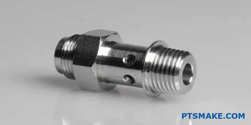
An impeller and shaft are essential components in pumps where the impeller is a rotating device that increases fluid pressure and flow, while the shaft is the central rod that transfers power from the motor to the impeller, enabling its rotation and pump operation.
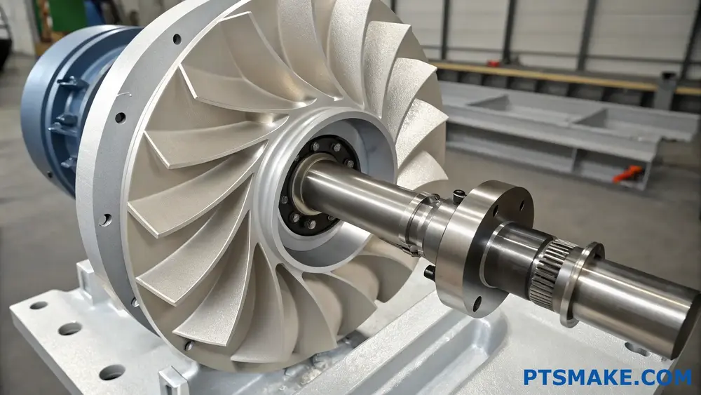
Understanding the Impeller’s Role
The impeller is the heart of any pump system. When I work with customers at PTSMAKE, I often explain that impellers are designed with specific blade patterns that create the necessary fluid movement. The centrifugal force2 generated by the rotating impeller blades pushes the fluid outward, creating the pressure needed for pumping.
Types of Impellers
Different applications require different impeller designs. Here are the main types:
| Impeller Type | Best Used For | Key Features |
|---|---|---|
| Closed | Clean liquids | Higher efficiency, enclosed vanes |
| Semi-open | Viscous fluids | Partially exposed vanes, good for handling solids |
| Open | Slurries and solids | Fully exposed vanes, less likely to clog |
| Vortex | Fibrous materials | Recessed design, minimal contact with fluid |
Material Considerations for Impellers
The choice of impeller material significantly impacts performance and longevity. At PTSMAKE, we recommend materials based on specific applications:
- Stainless Steel: Excellent for corrosive environments
- Bronze: Good for seawater applications
- Cast Iron: Suitable for general-purpose use
- Plastic Composites: Cost-effective for non-corrosive applications
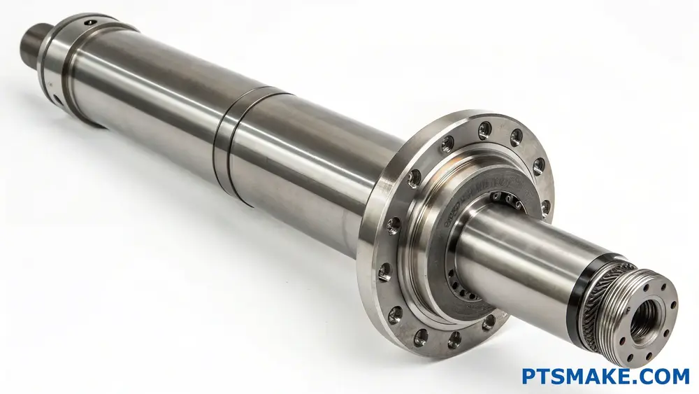
The Critical Role of the Shaft
The shaft is equally important as the impeller. It’s responsible for:
- Power transmission from motor to impeller
- Maintaining proper alignment
- Supporting radial and axial loads
- Ensuring smooth rotation
Shaft Design Considerations
Material Selection
- High-grade stainless steel for corrosion resistance
- Chrome-plated steel for wear resistance
- Carbon steel for general applications
Dimensional Factors
- Length to diameter ratio
- Critical speed calculations
- Deflection limitations
Common Shaft Problems and Solutions
Vibration Issues
- Proper balancing
- Alignment checks
- Regular maintenance
Wear Prevention
- Sleeve protection
- Proper lubrication
- Material upgrades
The Impeller-Shaft Connection
The connection between these components is crucial for optimal pump performance. Key aspects include:
Mounting Methods
- Keyed connections
- Splined shafts
- Threaded assemblies
Balance Requirements
- Static balancing
- Dynamic balancing
- Assembly tolerances
Maintenance Best Practices
To ensure long-term reliability:
Regular Inspection Schedule
- Weekly visual checks
- Monthly performance monitoring
- Quarterly comprehensive inspection
Performance Monitoring
- Flow rate tracking
- Pressure measurements
- Vibration analysis
Design Considerations for Different Applications
When designing impeller and shaft assemblies, several factors must be considered:
Operating Environment
- Temperature ranges
- Chemical exposure
- Pressure requirements
Performance Requirements
- Flow rate needs
- Head pressure
- Efficiency targets
Installation Constraints
- Space limitations
- Accessibility
- Maintenance requirements
At PTSMAKE, we’ve developed expertise in manufacturing precision components for pump systems. Our experience has shown that proper material selection and precise manufacturing tolerances are crucial for optimal performance. We use advanced CNC machining techniques to ensure each component meets exact specifications.
Impact on Pump Efficiency
The relationship between impeller and shaft design directly affects pump efficiency:
Energy Consumption
- Properly sized components reduce power usage
- Optimal clearances minimize losses
- Balance affects motor load
Operating Costs
- Initial investment vs. lifetime costs
- Maintenance requirements
- Energy efficiency considerations
Through proper design and manufacturing, these components work together to create an efficient pumping system. At PTSMAKE, we focus on precision manufacturing to ensure each component meets the highest standards of quality and performance.
How To Measure A Pump Shaft?
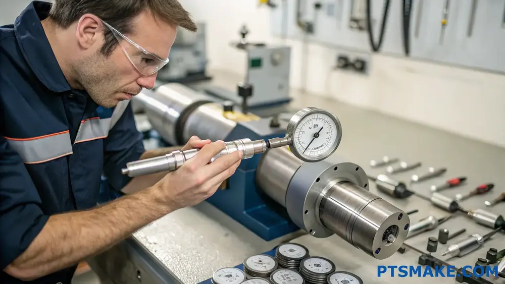
Taking accurate measurements of a pump shaft can be challenging, especially when precision is crucial for proper pump operation. I’ve seen many engineers struggle with incorrect measurements, leading to costly replacements and downtime.
To measure a pump shaft accurately, you’ll need precision measuring tools like micrometers and dial indicators. Focus on key dimensions including diameter, length, runout, and straightness while following proper measurement techniques and recording data systematically.
Essential Tools for Pump Shaft Measurement
Before diving into measurement techniques, let’s review the necessary tools:
Primary Measurement Tools
- Outside Micrometers (0-6 inch set)
- Digital Calipers (0-12 inch)
- Dial Indicators with Magnetic Base
- V-blocks for Support
- Surface Plate
- Roundness Meter
Supporting Equipment
- Cleaning Materials
- Calibration Standards
- Temperature Control Devices
- Documentation Forms
Critical Measurement Parameters
When measuring a pump shaft, several key dimensions require attention:
Diameter Measurements
The shaft diameter is crucial for proper fit and function. Here’s how to measure it:
- Clean the shaft surface thoroughly
- Use calibrated micrometers
- Take measurements at multiple points
- Record readings at 0°, 45°, 90°, and 135°
| Measurement Position | Tolerance Range (mm) | Typical Reading Points |
|---|---|---|
| Bearing Journal | ±0.013 | 4 positions per journal |
| Seal Area | ±0.025 | 3 positions minimum |
| Coupling Fit | ±0.013 | 4 positions minimum |
Length Measurements
Accurate length measurements ensure proper shaft positioning:
- Use digital calipers for overall length
- Measure individual section lengths
- Check shoulder distances
- Verify keyway positions
Advanced Measurement Techniques
Runout Measurement
Proper runout measurement is essential for shaft performance:
- Mount shaft between centers
- Set up dial indicator
- Rotate shaft slowly
- Record readings every 45°
| Runout Type | Maximum Allowable (mm) | Measurement Points |
|---|---|---|
| Total | 0.05 | Every 45° rotation |
| Bearing Area | 0.025 | Four positions minimum |
| Seal Area | 0.038 | Three positions minimum |
Straightness Verification
At PTSMAKE, we’ve developed a systematic approach to verify shaft straightness:
- Place shaft on V-blocks
- Set up dial indicator
- Measure at specified intervals
- Document deviation
Quality Control Considerations
Temperature Effects
Temperature variations can affect measurement accuracy:
- Maintain consistent room temperature
- Allow shaft to reach room temperature
- Use temperature compensation when needed
- Document environmental conditions
Documentation Requirements
Proper documentation ensures measurement traceability:
- Record all measurements
- Note environmental conditions
- Include calibration data
- Maintain digital records
Troubleshooting Common Issues
Measurement Errors
Common sources of measurement errors include:
- Tool calibration issues
- Environmental factors
- Operator technique
- Surface condition problems
Corrective Actions
To ensure accurate measurements:
- Regular tool calibration
- Proper operator training
- Environmental control
- Surface preparation standards
Best Practices and Industry Standards
In my experience working with precision components, following these practices ensures reliable measurements:
- Use calibrated tools
- Follow standardized procedures
- Maintain clean environment
- Document all readings
- Verify critical dimensions twice
Industry Standards Reference
| Standard | Application | Key Requirements |
|---|---|---|
| ISO 1101 | Geometrical Tolerancing | Form and position tolerances |
| ASME B89.1.5 | Measurement Uncertainty | Calculation methods |
| API 610 | Pump Requirements | Shaft tolerances |
Future Trends in Shaft Measurement
The industry is evolving with new technologies:
- 3D scanning systems
- Automated measurement
- Digital twin integration
- Real-time monitoring
At PTSMAKE, we’re continuously updating our measurement capabilities to stay ahead of these trends, ensuring our clients receive the highest quality precision manufacturing services.
What Is The Root Cause Of Shaft Failure?
Every day, countless industrial operations rely on pump shafts for critical processes. When these shafts fail unexpectedly, it leads to costly downtime, production losses, and potential safety hazards. I’ve seen manufacturing plants scramble to recover from sudden shaft failures, often without understanding the true cause.
The root cause of shaft failure typically stems from a combination of factors including misalignment, excessive vibration, material fatigue, and improper maintenance. Understanding these factors is crucial for preventing future failures and ensuring optimal equipment performance.
Understanding Material Fatigue and Stress
Material fatigue is one of the primary culprits behind shaft failure. When a shaft undergoes cyclic loading3, it experiences repeated stress that can lead to microscopic cracks. At PTSMAKE, we’ve developed comprehensive testing protocols to identify early signs of material fatigue.
Types of Stress That Impact Shaft Life
- Torsional Stress
- Bending Stress
- Axial Stress
- Combined Stress
Each type of stress contributes differently to potential failure modes. Here’s a detailed breakdown:
| Stress Type | Primary Cause | Impact on Shaft | Prevention Methods |
|---|---|---|---|
| Torsional | Power transmission | Twist deformation | Proper sizing and material selection |
| Bending | Misalignment | Surface cracking | Regular alignment checks |
| Axial | Thrust loads | Length changes | Thrust bearing installation |
| Combined | Multiple sources | Complex failure patterns | Comprehensive design review |
Misalignment: A Silent Destroyer
In my extensive experience at PTSMAKE, I’ve observed that misalignment is often overlooked until it’s too late. There are three main types of misalignment:
Angular Misalignment
- Creates uneven stress distribution
- Causes premature bearing failure
- Results in excessive vibration
Parallel Misalignment
- Leads to increased radial loads
- Accelerates seal wear
- Generates excessive heat
Combination Misalignment
- Most common in real-world applications
- Compounds stress factors
- Requires precise correction methods
Environmental Factors and Operating Conditions
The environment plays a crucial role in shaft longevity. Key considerations include:
Temperature Effects
- Thermal expansion and contraction
- Material property changes
- Lubrication effectiveness
Chemical Exposure
- Corrosion risks
- Material degradation
- Seal compatibility issues
Maintenance and Prevention Strategies
At PTSMAKE, we emphasize the importance of preventive maintenance. Our approach includes:
Regular Inspection Protocol
- Visual checks for surface damage
- Vibration analysis
- Alignment verification
- Bearing condition monitoring
Proper Installation Practices
| Installation Step | Key Considerations | Common Mistakes |
|---|---|---|
| Alignment | Use precision tools | Rushing the process |
| Mounting | Follow torque specs | Improper fitting |
| Balance | Check dynamic balance | Ignoring small imbalances |
| Lubrication | Use correct type | Wrong quantity |
Design Considerations for Shaft Reliability
Through our manufacturing expertise at PTSMAKE, we’ve identified critical design elements:
Material Selection
- Consider operating environment
- Account for load requirements
- Factor in cost-effectiveness
Dimensional Optimization
- Stress concentration reduction
- Proper diameter ratios
- Adequate clearances
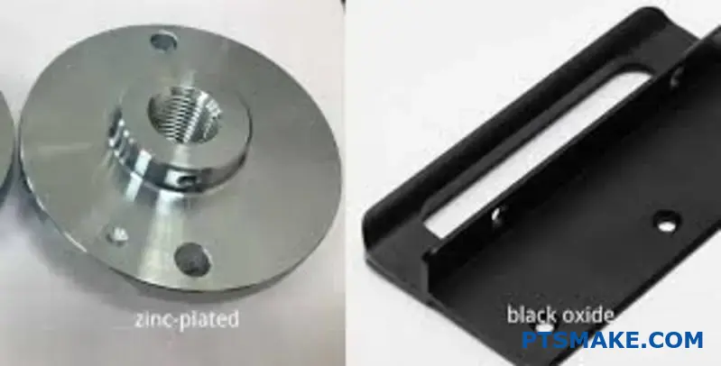
Surface Treatment
- Appropriate finishing methods
- Hardening requirements
- Coating selections
Troubleshooting and Analysis
When shaft failure occurs, systematic analysis is crucial:
Investigation Steps
- Document failure conditions
- Collect operating data
- Examine failure patterns
- Analyze material properties
Common Failure Patterns
| Pattern Type | Characteristics | Likely Causes |
|---|---|---|
| Fatigue | Beach marks | Cyclic loading |
| Torsional | 45-degree cracks | Overload |
| Corrosion | Pitting | Chemical attack |
| Wear | Surface scoring | Poor lubrication |
This comprehensive understanding of shaft failure causes helps in implementing effective prevention strategies. At PTSMAKE, we’ve successfully helped numerous clients optimize their shaft designs and maintenance procedures, significantly reducing failure rates and improving operational reliability.
How To Calculate The Shaft Work Of A Pump?
When managing pump systems, many engineers struggle with accurate shaft work calculations. The complexity of variables and potential for calculation errors can lead to inefficient pump operation and increased energy costs.
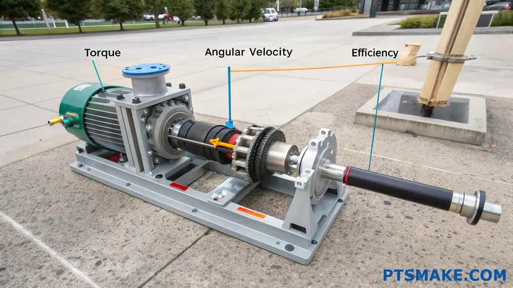
Shaft work in pumps represents the mechanical energy transferred from the pump’s motor to the fluid through the shaft. It’s calculated by multiplying the torque by the angular velocity, considering factors like efficiency losses and fluid properties.
Understanding Shaft Work Components
Basic Principles
The foundation of pump shaft work calculation lies in understanding how energy transfers through the system. I often explain to my clients that shaft work isn’t just about power input – it’s about how effectively that power converts to fluid movement. The mechanical efficiency plays a crucial role in this energy transfer process.
Essential Variables
When calculating shaft work, several key variables must be considered:
| Variable | Symbol | Unit |
|---|---|---|
| Torque | τ | N⋅m |
| Angular Velocity | ω | rad/s |
| Power Input | Pin | Watts |
| Efficiency | η | % |
Calculation Methods
Standard Formula Method
The basic formula for shaft work (Ws) is:
Ws = τ × ωWhere:
- τ is the torque applied to the shaft
- ω is the angular velocity of the shaft
Efficiency Considerations
Based on my experience in pump manufacturing at PTSMAKE, I’ve observed that real-world applications require accounting for efficiency losses. The actual shaft work needed is often higher than theoretical calculations suggest due to:
- Mechanical losses
- Fluid friction
- Internal leakage
- Bearing losses
Advanced Calculation Techniques
Power-Based Calculation
Another approach I frequently use involves calculating shaft work through power relationships:
| Parameter | Formula | Description |
|---|---|---|
| Input Power | Pin = V × I × PF | Electrical input power |
| Shaft Power | Ps = Pin × ηm | Mechanical power transferred |
| Hydraulic Power | Ph = Ps × ηh | Power delivered to fluid |
Flow Rate Integration
For variable flow systems, we must consider:
- Flow rate variations
- System pressure changes
- Fluid properties
- Operating conditions
Practical Applications
Having worked with numerous pump installations, I recommend following these steps:
- Determine the required flow rate and head
- Calculate theoretical power requirements
- Factor in system-specific efficiency losses
- Apply safety margins for operational flexibility
Real-World Considerations
At PTSMAKE, we’ve developed comprehensive testing procedures to ensure accurate shaft work calculations. Key factors include:
- Operating temperature effects
- Fluid viscosity changes
- System resistance variations
- Start-up conditions
Troubleshooting Common Issues
Calculation Errors
Common mistakes to avoid:
- Ignoring efficiency factors
- Using incorrect units
- Failing to account for system curves
- Overlooking fluid property changes
Performance Optimization
To optimize shaft work calculations:
- Regularly calibrate measurement instruments
- Monitor system efficiency trends
- Update calculations based on actual performance data
- Implement predictive maintenance strategies
Impact on System Design
Understanding shaft work calculations affects:
- Motor selection
- Shaft sizing
- Bearing specifications
- Coupling requirements
This knowledge helps in designing more efficient and reliable pumping systems. At PTSMAKE, we utilize this understanding to manufacture precision components that optimize pump performance and reliability.
Future Considerations
The field of pump shaft work calculation continues to evolve with:
- Advanced modeling software
- Real-time monitoring systems
- Automated calculation tools
- IoT integration possibilities
These developments are making calculations more accurate and accessible, though fundamental understanding remains crucial for proper implementation and troubleshooting.
What Is The Main Function Of The Pump Shaft?
Have you ever experienced a sudden pump failure that brought your entire operation to a halt? The consequences can be severe – production delays, costly repairs, and frustrated teams. Many of these issues often trace back to one critical component that’s frequently overlooked: the pump shaft.
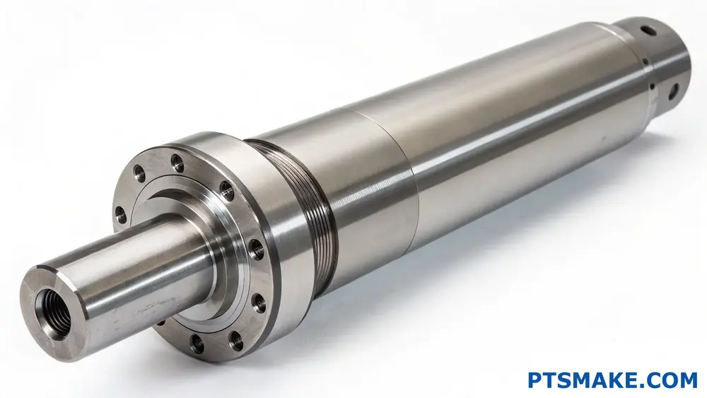
The pump shaft serves as the central component that transmits rotational power from the motor to the impeller, enabling the conversion of mechanical energy into hydraulic energy. This crucial element maintains proper alignment and supports the dynamic loads within the pump system.
Understanding the Core Functions of a Pump Shaft
Power Transmission
The primary function of a pump shaft is power transmission. When I design pump shafts at PTSMAKE, I ensure they can handle the torsional stress4 that occurs during operation. The shaft must efficiently transfer power from the drive motor to the pump impeller while maintaining structural integrity.
Load Support
A pump shaft must support various loads, including:
- Radial loads from impeller forces
- Axial loads from system pressure
- Weight of rotating components
- Dynamic forces during operation
Critical Design Considerations
Material Selection
The choice of shaft material significantly impacts performance. At PTSMAKE, we carefully select materials based on specific application requirements:
| Material Type | Advantages | Best Applications |
|---|---|---|
| Stainless Steel | Corrosion resistant, high strength | Chemical processing, food grade |
| Carbon Steel | Cost-effective, good strength | General industrial use |
| Alloy Steel | Superior strength, wear resistant | Heavy-duty applications |
| Duplex Steel | Combined strength and corrosion resistance | Marine environments |
Dimensional Accuracy
Proper shaft sizing is crucial for:
- Minimizing deflection
- Reducing vibration
- Ensuring proper bearing fit
- Maintaining seal integrity
Performance Factors
Speed Requirements
The shaft must handle operational speeds while maintaining:
- Rotational balance
- Critical speed margins
- Vibration control
- Smooth power delivery
Environmental Considerations
Environmental factors affecting shaft performance include:
- Operating temperature
- Chemical exposure
- Moisture levels
- Particulate presence
Manufacturing Process Impact
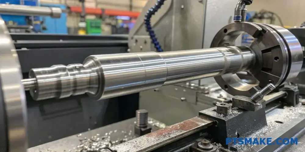
Precision Machining
At PTSMAKE, our CNC machining expertise ensures:
- Exact dimensional tolerances
- Superior surface finish
- Proper material properties
- Consistent quality
Quality Control
Our quality assurance process involves:
- Material certification
- Dimensional inspection
- Surface finish verification
- Alignment checking
- Dynamic balancing
Maintenance Considerations
Regular Inspection
Proper shaft maintenance includes checking for:
- Wear patterns
- Alignment issues
- Surface damage
- Bearing condition
- Seal performance
Preventive Measures
To extend shaft life, consider:
- Regular lubrication
- Alignment checks
- Vibration monitoring
- Temperature monitoring
- Load management
System Integration
Coupling Selection
The right coupling ensures:
- Proper power transmission
- Misalignment compensation
- Vibration dampening
- Easy maintenance
Bearing Configuration
Proper bearing selection impacts:
- Load distribution
- Shaft alignment
- Operating temperature
- System reliability
Performance Optimization
Efficiency Factors
Key elements affecting shaft efficiency:
- Material properties
- Surface finish
- Alignment precision
- Balance quality
- Design optimization
Reliability Enhancement
To maximize reliability, focus on:
- Proper sizing
- Material selection
- Manufacturing quality
- Installation procedures
- Maintenance protocols
At PTSMAKE, we understand that a well-designed and properly manufactured pump shaft is crucial for system reliability. Our experience in precision manufacturing allows us to produce shafts that meet the most demanding specifications. We employ advanced CNC machining techniques and rigorous quality control measures to ensure each shaft delivers optimal performance.
The success of a pump system largely depends on the quality of its shaft. Through careful attention to design, material selection, manufacturing precision, and proper maintenance, a pump shaft can provide years of reliable service. Whether you need custom shaft solutions or standard replacements, understanding these fundamental aspects helps ensure successful pump operation.
What Materials Are Best Suited For Pump Shafts In High-Stress Applications?
Selecting the wrong material for pump shafts in high-stress applications can lead to catastrophic failures. I’ve seen pumps fail during critical operations, causing expensive downtime and safety risks. These failures often stem from material fatigue, corrosion, or inability to handle extreme loads.
The best materials for pump shafts in high-stress applications are typically stainless steel grades like 316 and 17-4 PH, duplex stainless steels, and high-strength alloy steels. These materials offer excellent combinations of strength, corrosion resistance, and fatigue properties.
Understanding Material Requirements for Pump Shafts
When designing pump shafts for demanding applications, material selection becomes crucial. The chosen material must exhibit specific properties to ensure reliable performance under various operating conditions. At PTSMAKE, we regularly machine pump shafts using different materials based on their yield strength5 and application requirements.
Key Material Properties to Consider
- Tensile Strength
- Fatigue Resistance
- Corrosion Resistance
- Wear Resistance
- Thermal Stability
Common Materials for High-Stress Pump Shafts
Stainless Steel Grades
Stainless steel remains the most popular choice for pump shafts due to its excellent balance of properties. Here’s a detailed breakdown of commonly used grades:
| Grade | Tensile Strength (MPa) | Corrosion Resistance | Cost Factor |
|---|---|---|---|
| 316L | 485 | Excellent | Moderate |
| 17-4 PH | 1070 | Very Good | High |
| 904L | 490 | Superior | Very High |
Duplex Stainless Steels
These materials offer superior strength and corrosion resistance compared to standard stainless steels. Common grades include:
| Grade | Key Benefits | Typical Applications |
|---|---|---|
| 2205 | High strength, good chloride resistance | Chemical processing |
| 2507 | Superior corrosion resistance | Offshore pumps |
| S32760 | Excellent pitting resistance | Marine applications |
Special Considerations for Different Applications
Chemical Processing Industry
In chemical processing, corrosion resistance becomes paramount. We often recommend:
- Super Duplex Stainless Steel
- Hastelloy C-276
- Inconel 625
Water Treatment Applications
For water treatment pumps, consider:
- 316L Stainless Steel
- Duplex 2205
- Carbon Steel with protective coating
Material Selection Based on Operating Conditions
Temperature Considerations
The operating temperature significantly influences material selection:
| Temperature Range | Recommended Materials |
|---|---|
| Below 0°C | Low-temperature alloy steels |
| 0-200°C | Standard stainless steels |
| Above 200°C | High-temperature alloys |
Pressure Requirements
High-pressure applications demand materials with superior mechanical properties:
- High-strength alloy steels
- Precipitation-hardened stainless steels
- Nickel-based alloys
Manufacturing Considerations
At PTSMAKE, we understand that material selection also impacts manufacturing processes. Key factors include:
- Machinability
- Heat treatment requirements
- Surface finish capabilities
- Cost effectiveness
Machining Challenges
Different materials present various machining challenges:
| Material | Machining Difficulty | Special Requirements |
|---|---|---|
| 316L | Moderate | Sharp tools, proper cooling |
| 17-4 PH | High | Special tooling, precise parameters |
| Duplex | Very High | Enhanced cooling, rigid setup |
Cost-Benefit Analysis
When selecting materials, consider:
- Initial material cost
- Manufacturing expenses
- Expected service life
- Maintenance requirements
- Replacement frequency
Quality Control and Testing
To ensure pump shaft reliability, we implement:
- Material certification verification
- Non-destructive testing
- Dimensional inspection
- Surface finish measurement
- Hardness testing
Future Trends in Pump Shaft Materials
The industry is moving towards:
- Advanced composite materials
- Novel surface treatments
- Hybrid material solutions
- Smart materials with monitoring capabilities
At PTSMAKE, we stay ahead of these trends by continually updating our manufacturing capabilities and material knowledge base.
Maintenance Considerations
Proper material selection affects maintenance requirements:
- Inspection intervals
- Lubrication needs
- Repair possibilities
- Replacement strategies
Understanding these factors helps optimize the total cost of ownership while maintaining reliable operation.
How To Prevent Premature Wear In CNC-Machined Pump Shafts?
Every day, I encounter clients struggling with premature wear in their pump shafts, leading to unexpected equipment failures and costly downtime. The frustration of dealing with frequent replacements and maintenance not only impacts productivity but also significantly increases operational costs.
To prevent premature wear in CNC-machined pump shafts, focus on material selection, surface finishing, proper alignment, and lubrication systems. These key factors, combined with regular maintenance and monitoring, can significantly extend the shaft’s service life.
Material Selection and Treatment
The foundation of a durable pump shaft starts with proper material selection. At PTSMAKE, I’ve found that choosing the right material significantly impacts shaft longevity. The material must withstand work hardening while maintaining its structural integrity.
Common Materials for Pump Shafts
| Material | Advantages | Best Applications |
|---|---|---|
| 316 Stainless Steel | Corrosion resistant, good strength | Chemical processing pumps |
| 17-4 PH Steel | High strength, good hardness | High-pressure applications |
| Duplex Steel | Superior corrosion resistance | Marine environments |
| Carbon Steel | Cost-effective, easily machinable | General purpose pumps |
Surface Finishing Techniques
Surface finish quality directly affects shaft performance. Through precise CNC machining processes, we achieve optimal surface characteristics:
Critical Surface Parameters
- Roughness (Ra) values below 0.4 μm
- Proper cylindricity tolerance
- Controlled roundness specifications
- Surface pattern optimization
Alignment and Installation Considerations
Even the best-manufactured shaft can fail prematurely if not properly aligned. Key factors include:
Proper Alignment Methods
- Laser alignment systems
- Dial indicator measurements
- Digital shaft alignment tools
- Regular alignment checks
Lubrication System Design
Effective lubrication is crucial for preventing wear. Consider these aspects:
Lubrication Optimization Strategies
| Strategy | Purpose | Implementation |
|---|---|---|
| Oil Analysis | Monitor wear patterns | Regular testing schedule |
| Film Thickness | Maintain separation | Proper oil selection |
| Flow Rate | Ensure coverage | System design optimization |
| Temperature Control | Maintain viscosity | Cooling system integration |
Environmental Protection Measures
Environmental factors significantly impact shaft longevity:
Protection Strategies
- Sealed bearing arrangements
- Environmental shields
- Protective coatings
- Regular cleaning protocols
Quality Control During Manufacturing
At PTSMAKE, we implement rigorous quality control measures:
Key Inspection Points
- Dimensional accuracy
- Material certification
- Surface finish verification
- Hardness testing
- Concentricity checks
Maintenance Protocols
Establishing proper maintenance routines is essential:
Maintenance Schedule Components
| Timeframe | Action Items | Purpose |
|---|---|---|
| Daily | Visual inspection | Detect obvious issues |
| Weekly | Vibration monitoring | Identify early problems |
| Monthly | Alignment check | Maintain proper setup |
| Quarterly | Complete inspection | Comprehensive evaluation |
Load Management
Understanding and managing operational loads extends shaft life:
Load Control Measures
- Operating within design parameters
- Monitoring system pressure
- Controlling start-up procedures
- Managing thermal loads
Design Optimization
Proper design considerations prevent premature wear:
Critical Design Elements
- Shaft diameter optimization
- Stress concentration reduction
- Bearing spacing calculation
- Material transition zones
Advanced Monitoring Systems
Modern monitoring helps prevent failures:
Monitoring Technologies
- Vibration analysis
- Temperature monitoring
- Oil particle analysis
- Performance trending
Implementation Strategy
To successfully implement these preventive measures:
- Document baseline conditions
- Train maintenance personnel
- Establish monitoring protocols
- Create response procedures
- Review and update practices
Through implementing these comprehensive strategies, we’ve helped numerous clients significantly extend their pump shaft life spans. The key is taking a systematic approach to prevention rather than dealing with failures reactively. At PTSMAKE, we’ve refined these practices through years of experience in CNC machining pump shafts for various industries, ensuring optimal performance and longevity for our clients’ equipment.
What Design Features Improve Pump Shaft Durability For Industrial Use?
Pump shaft failures can lead to catastrophic breakdowns in industrial operations, causing extensive downtime and substantial financial losses. I’ve witnessed numerous cases where companies struggle with premature shaft wear, misalignment issues, and unexpected failures that could have been prevented with proper design considerations.
The key design features that improve pump shaft durability include optimized material selection, proper shaft diameter sizing, adequate bearing support, effective sealing systems, and precise alignment specifications. These elements work together to enhance shaft longevity and overall pump performance.
Material Selection Considerations
Material selection plays a crucial role in pump shaft durability. At PTSMAKE, we carefully evaluate various materials based on specific application requirements. The most common materials include:
High-Grade Stainless Steel Options
- 316 Stainless Steel: Excellent corrosion resistance
- 17-4 PH: Superior strength and hardness
- Duplex Steel: Combined strength and corrosion resistance
The choice of material significantly affects the shaft’s yield strength and overall performance.
Geometric Design Elements
Shaft Diameter Optimization
The diameter of the pump shaft must be carefully calculated to handle:
- Torsional stress
- Bending moments
- Critical speed requirements
- Deflection limits
| Shaft Size (mm) | Load Capacity (kN) | Speed Range (RPM) |
|---|---|---|
| 20-30 | 5-15 | 1000-3000 |
| 31-50 | 16-40 | 800-2500 |
| 51-75 | 41-80 | 600-2000 |
Stress Concentration Management
- Implementing gradual diameter transitions
- Using optimal fillet radius
- Minimizing keyway impact
- Proper groove design for seals
Bearing System Design
The bearing system is fundamental for shaft support and alignment. Key considerations include:
Bearing Selection Criteria
- Load requirements
- Speed limitations
- Temperature considerations
- Lubrication needs
Bearing Spacing
Proper bearing spacing helps:
- Minimize shaft deflection
- Reduce vibration
- Optimize load distribution
- Improve overall stability
Sealing System Integration
Mechanical Seal Design
Modern mechanical seals require:
- Precise face materials
- Optimal spring loading
- Proper flush arrangements
- Environmental controls
Shaft Sleeve Considerations
Protective sleeves should be designed with:
- Hardness requirements
- Surface finish specifications
- Proper clearance tolerances
- Material compatibility
Dynamic Balance Requirements
Achieving proper dynamic balance involves:
Balance Grade Selection
| Balance Grade | Application Type | Max RPM |
|---|---|---|
| G1.0 | Precision Pumps | >3000 |
| G2.5 | Standard Industrial | 1500-3000 |
| G6.3 | General Purpose | <1500 |
Vibration Control Measures
- Implementation of vibration monitoring
- Regular maintenance schedules
- Alignment checking procedures
- Balance correction methods
Manufacturing Considerations
At PTSMAKE, we ensure optimal shaft manufacturing through:
Surface Finish Requirements
- Proper grinding techniques
- Surface roughness control
- Heat treatment processes
- Quality inspection methods
Dimensional Tolerances
Critical tolerances include:
- Concentricity specifications
- Roundness requirements
- Straightness limits
- Run-out controls
Environmental Protection Features
Corrosion Prevention
- Protective coatings application
- Material selection for specific environments
- Cathodic protection when needed
- Regular maintenance procedures
Temperature Management
- Cooling system integration
- Heat dissipation design
- Temperature monitoring
- Thermal expansion accommodation
Maintenance Considerations
To ensure long-term durability, design features should facilitate:
Easy Access
- Removable coupling guards
- Accessible lubrication points
- Simplified assembly/disassembly
- Clear maintenance marking
Monitoring Capabilities
- Vibration sensor mounting points
- Temperature measurement locations
- Pressure monitoring provisions
- Alignment check features
Through these comprehensive design considerations, pump shafts can achieve optimal durability and performance in industrial applications. These features not only extend service life but also reduce maintenance costs and improve overall system reliability. At PTSMAKE, we incorporate these design elements into our manufacturing processes to ensure the highest quality and longevity of our pump components.
Learn how cyclic loading impacts material fatigue and shaft failures to improve reliability. ↩
Understanding centrifugal force helps optimize pump design for better performance and efficiency. ↩
Learn about cyclic loading to prevent material fatigue and enhance shaft reliability." ↩
Learn how to manage torsional stress for better pump efficiency and longevity. ↩
Learn about yield strength to choose materials that ensure reliability and performance in high-stress applications. ↩