I often see engineers struggling with drawings that lack proper fit specifications. This confusion leads to costly production errors and parts that don’t assemble correctly. I’ve witnessed projects fail simply because someone misunderstood the transition fit requirements.
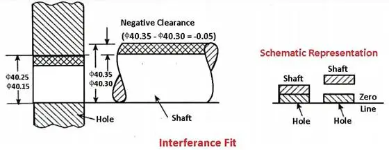
A transition fit occurs when the difference between a hole and shaft creates either a slight clearance or interference. This fit type is commonly used in applications where parts need to be assembled by hand while maintaining accurate positioning.
Let me share something interesting about transition fits that many people overlook. While these fits might seem straightforward at first, they actually offer unique advantages in assembly. The slight interference or clearance they provide can make the difference between a smooth-running machine and one that fails prematurely. I’ll explain why this matters for your next project.
When Would You Use a Transition Fit?
Have you ever struggled with parts that neither slide together smoothly nor provide a secure grip? The frustration of components that are either too loose or too tight can lead to assembly nightmares, performance issues, and costly rework. It’s a common challenge that can make or break your project’s success.
A transition fit is ideal when you need components that can be assembled by hand with light force while maintaining reasonable positioning accuracy. This fit type provides a slight interference to clearance range, making it perfect for parts requiring occasional disassembly or temporary positioning.
Understanding the Basics of Transition Fits
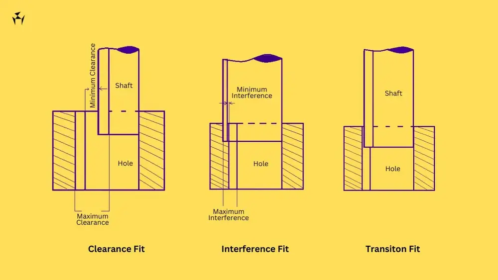
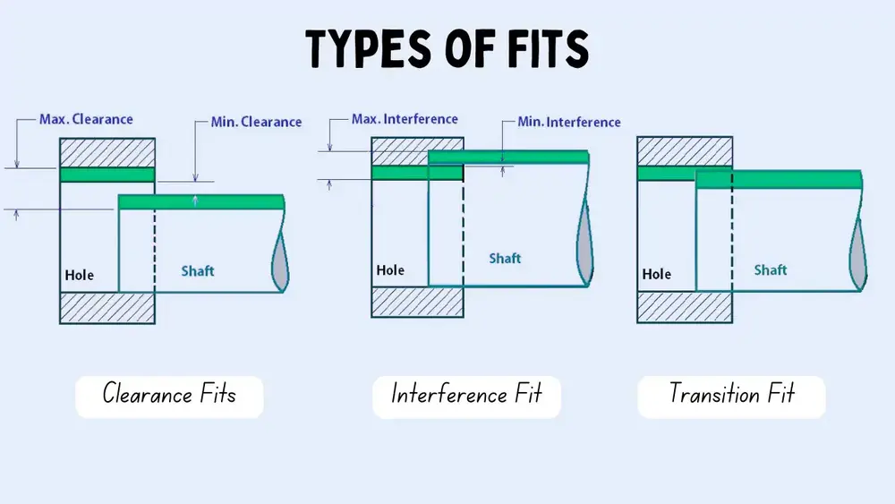
Transition fits occupy the middle ground between clearance and interference fits. They create a unique connection where the actual fit could range from a slight interference to a minimal clearance. The shaft-to-hole tolerance zone1 plays a crucial role in determining the final assembly characteristics.
Key Characteristics of Transition Fits
- Minimal to zero clearance
- Light assembly force required
- Suitable for manual assembly
- Maintains reasonable accuracy
- Allows for occasional disassembly
Common Applications of Transition Fits
Manufacturing and Assembly
In precision manufacturing, transition fits are extensively used for:
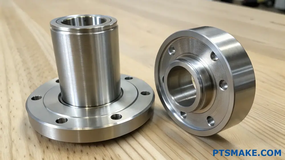
- Positioning bushings in housings
- Mounting bearings on shafts
- Assembly of gear components
- Locating pins and dowels
- Temporary fixture components
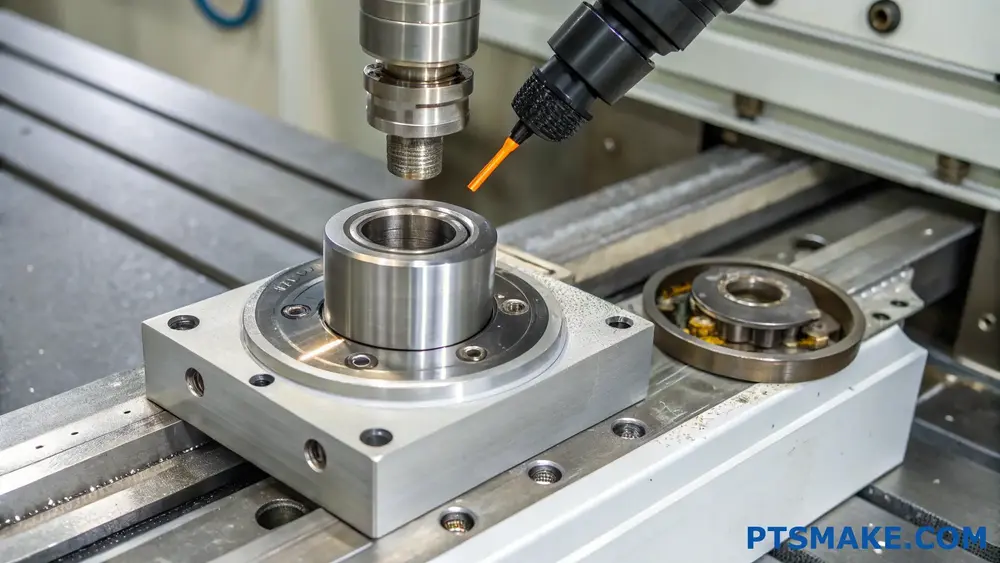
At PTSMAKE, we frequently employ transition fits in our CNC machining projects, especially when clients need components that balance ease of assembly with positioning accuracy.
Industry-Specific Applications
Different industries leverage transition fits for various purposes:
| Industry | Application Examples | Key Benefits |
|---|---|---|
| Automotive | Bearing carriers, wheel hubs | Easy maintenance, consistent alignment |
| Aerospace | Guide bushings, mounting brackets | Precise positioning, vibration resistance |
| Medical | Instrument housings, device frames | Sterilization compatibility, reliable assembly |
| Electronics | Heat sinks, component mounts | Thermal expansion accommodation, serviceability |
Selection Criteria for Transition Fits
Functional Requirements
When choosing a transition fit, consider:
- Assembly frequency
- Required positioning accuracy
- Operating conditions
- Maintenance needs
- Cost considerations
Environmental Factors
Various environmental conditions affect transition fit performance:
- Temperature fluctuations
- Humidity levels
- Vibration exposure
- Chemical exposure
- Operating pressures
Design Considerations
Tolerance Analysis
Proper tolerance analysis ensures successful transition fit implementation:
- Calculate maximum material condition
- Evaluate minimum material condition
- Consider stack-up tolerances
- Account for thermal expansion
- Factor in manufacturing capabilities
Material Selection
Material properties significantly impact transition fit behavior:
- Thermal expansion coefficients
- Surface hardness
- Wear resistance
- Corrosion resistance
- Cost-effectiveness
Manufacturing Guidelines
Production Methods
To achieve reliable transition fits:
- Maintain strict dimensional control
- Use appropriate surface finishes
- Consider post-processing requirements
- Implement proper inspection methods
- Document assembly procedures
Quality Control Measures
Essential quality control practices include:
- Regular calibration of measuring equipment
- Statistical process control
- First article inspection
- Environmental condition monitoring
- Documentation of results
Maintenance and Serviceability
Assembly Procedures
Best practices for assembly:
- Clean mating surfaces thoroughly
- Use appropriate assembly tools
- Apply uniform pressure
- Monitor assembly force
- Document assembly process
Disassembly Considerations
Important factors for successful disassembly:
- Use proper extraction tools
- Apply even force distribution
- Monitor component condition
- Plan for replacement parts
- Document maintenance history
Cost Implications
Manufacturing Costs
Factors affecting production costs:
- Tighter tolerances requirements
- Surface finish specifications
- Material selection
- Production volume
- Quality control measures
Lifecycle Considerations
Long-term cost factors include:
- Maintenance requirements
- Component replacement frequency
- Assembly/disassembly labor
- Downtime impacts
- Tool and equipment needs
What Is the Primary Reason to Use a Transition Fit?
Have you ever struggled with assembly components that either fit too loosely or too tightly? The frustration of dealing with parts that won’t align properly can turn a simple assembly task into a time-consuming nightmare, leading to production delays and increased costs.
The primary reason to use a transition fit is to achieve a precise balance between clearance and interference fits. It provides controlled movement between mating parts while maintaining accurate positioning, making it ideal for components that require occasional assembly and disassembly.
Understanding the Mechanics of Transition Fits
Transition fits occupy a unique position in engineering design, falling between clearance and interference fits. They’re characterized by their dimensional tolerance overlap2, which means the maximum shaft size can be slightly larger than the minimum hole size, or vice versa.
Key Characteristics of Transition Fits
The success of a transition fit depends on several crucial factors:
Surface Finish Quality
- Smoother surfaces reduce friction
- Prevents wear during assembly
- Enhances component longevity
Material Properties
- Thermal expansion coefficients
- Hardness compatibility
- Wear resistance
Assembly Requirements
- Frequency of disassembly
- Load conditions
- Operating environment
Common Applications in Manufacturing
At PTSMAKE, we frequently work with transition fits in various applications:
Automotive Components
Transition fits are essential in automotive manufacturing for:
- Bearing mountings
- Gear assemblies
- Shaft couplings
- Wheel hubs
Precision Machinery
In precision equipment, these fits ensure:
- Proper alignment of rotating components
- Controlled movement in sliding mechanisms
- Accurate positioning of guide bushings
Selection Criteria for Transition Fits
When choosing a transition fit, consider these factors:
| Factor | Consideration | Impact |
|---|---|---|
| Operating Temperature | Thermal expansion range | Affects fit tightness |
| Load Type | Static vs. Dynamic | Determines required interference |
| Assembly Method | Manual vs. Machine | Influences tolerance selection |
| Environmental Conditions | Moisture, dust exposure | Affects sealing requirements |
Design Considerations and Best Practices
To optimize transition fit applications:
Tolerance Analysis
- Calculate stack-up tolerances
- Consider manufacturing capabilities
- Account for material variations
Material Selection Guidelines
Choose materials based on:
- Wear characteristics
- Thermal properties
- Cost considerations
- Environmental factors
Manufacturing Challenges and Solutions
When working with transition fits, several challenges often arise:
Precision Requirements
Maintaining tight tolerances requires:
- Advanced measurement systems
- Temperature-controlled environments
- Skilled operators
Quality Control Measures
Implement comprehensive inspection procedures:
- Regular calibration checks
- Statistical process control
- Documentation of critical dimensions
Cost Implications and Economic Considerations
Understanding the financial aspects of transition fits is crucial:
Manufacturing Costs
- Precision machining requirements
- Special tooling needs
- Quality control expenses
Long-term Benefits
- Reduced maintenance costs
- Improved assembly efficiency
- Extended component life
Optimization Strategies
To maximize the effectiveness of transition fits:
Design Phase
- Use FEA analysis for stress distribution
- Simulate assembly conditions
- Validate tolerance stack-ups
Production Phase
- Implement proper machining sequences
- Monitor environmental conditions
- Maintain strict quality control
Future Trends and Innovations
The field of transition fits continues to evolve:
Advanced Manufacturing Technologies
- 3D printing applications
- Smart manufacturing integration
- Automated inspection systems
Material Developments
- New alloy compositions
- Surface treatment innovations
- Smart materials application
Industry Standards and Specifications
Following international standards ensures consistency:
ISO Standards
- ISO 286 for limit and fits
- Tolerance grade selections
- Surface finish requirements
Regional Variations
- ANSI/ASME standards
- DIN specifications
- JIS requirements
How Tight Is a Transition Fit?
Have you ever struggled with parts that won’t quite fit together, despite your precise measurements? Or faced the frustrating dilemma of components being either too loose or too tight? These fitting issues can turn a simple assembly into a manufacturing nightmare.
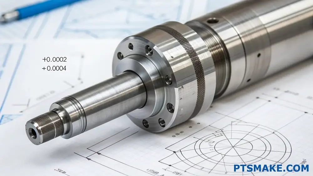
A transition fit occurs when the difference between a shaft and hole dimension creates either a slight clearance or interference, typically ranging from +0.0002 to -0.0004 inches. This fit type provides a unique balance between clearance and interference fits.
Understanding Transition Fit Basics
Transition fits represent a crucial middle ground in mechanical engineering. They combine characteristics of both clearance and interference fits, making them ideal for components that require precise positioning while still allowing for occasional disassembly. The unique aspect of transition fits lies in their statistical tolerance distribution3, which determines the actual fit condition.
Key Characteristics of Transition Fit
- Dimensional Variation
- Assembly Requirements
- Application Flexibility
- Manufacturing Considerations
Common Applications
Transition fits find extensive use in various industrial applications where precise positioning is crucial:
- Bearing installations in housings
- Gear mounting on shafts
- Pulley and flywheel assemblies
- Precision machinery components
Measuring and Calculating Transition Fits
The accuracy of transition fits depends on precise measurements and calculations. Here’s a detailed breakdown of the standard tolerances:
| Fit Class | Shaft Tolerance | Hole Tolerance | Typical Application |
|---|---|---|---|
| FN1 | -0.0002 to +0.0002 | 0 to +0.0004 | Light duty assemblies |
| FN2 | -0.0003 to +0.0001 | 0 to +0.0004 | Medium duty assemblies |
| FN3 | -0.0004 to 0 | 0 to +0.0004 | Heavy duty assemblies |
Factors Affecting Transition Fit Quality
Material Properties
The choice of materials significantly impacts the success of a transition fit. Different materials exhibit varying thermal expansion rates and surface characteristics. At PTSMAKE, we carefully consider material properties when recommending specific transition fit tolerances to our clients.
Temperature Effects
Temperature variations can significantly affect fit dimensions:
- Thermal expansion during operation
- Assembly temperature considerations
- Material-specific expansion rates
Surface Finish Requirements
Surface finish plays a crucial role in achieving optimal transition fits:
- Roughness parameters
- Waviness considerations
- Surface treatment effects
Design Considerations for Transition Fits
Tolerance Stack-up Analysis
When designing assemblies with transition fits, consider:
- Component tolerances
- Assembly sequence
- Cumulative effects of multiple fits
Manufacturing Process Selection
The manufacturing process significantly influences fit quality:
- Machining precision requirements
- Cost considerations
- Production volume implications
Quality Control Measures
Implementing proper quality control is essential:
- Measurement techniques
- Inspection procedures
- Documentation requirements
Best Practices for Implementation
Pre-assembly Preparations
Proper preparation ensures successful assembly:
- Clean and debris-free surfaces
- Appropriate lubricants when needed
- Correct tooling selection
Assembly Techniques
Following proper assembly procedures is crucial:
- Alignment considerations
- Force application methods
- Temperature management
Maintenance Considerations
Long-term performance depends on proper maintenance:
- Regular inspection schedules
- Lubrication requirements
- Wear monitoring
Troubleshooting Common Issues
Fit Problems
Common issues and solutions include:
- Excessive interference
- Insufficient grip
- Uneven assembly
Prevention Strategies
Preventive measures to ensure successful fits:
- Design validation
- Process control
- Material selection verification
In my experience at PTSMAKE, successful transition fits require careful attention to detail throughout the design and manufacturing process. We’ve developed comprehensive quality control procedures to ensure our machined components meet exact specifications for transition fits. This attention to detail has helped us maintain our position as a trusted partner for precision manufacturing across various industries.
What Is the Difference Between Free Fit and Close Fit?
Have you ever assembled parts only to find they either won’t fit together or wobble loosely? This common frustration can lead to project delays, wasted materials, and compromised product quality. It’s a challenge that leaves many designers and engineers scratching their heads.
Free fit and close fit represent two distinct fitting types in mechanical engineering. Free fit allows considerable clearance between mating parts for easy assembly, while close fit provides minimal clearance for precise alignment and reduced movement between components.
Understanding the Basics of Fits
Free Fit Characteristics
Free fits are designed to provide generous clearance between mating parts. When dealing with free fits, parts can be easily assembled and disassembled by hand without any special tools. These fits are particularly useful in situations where quick maintenance or frequent part replacement is necessary.
The clearance interference4 in free fits typically ranges from loose to very loose, making them ideal for components that:
- Need regular maintenance
- Require quick assembly
- Must move freely relative to each other
- Operate in high-temperature environments where thermal expansion is a concern
Close Fit Characteristics
Close fits feature minimal clearance between mating parts, resulting in a more precise assembly. These fits often require light pressure or gentle tapping for assembly but can still be taken apart without damaging the components. Close fits are essential when:
- Precise positioning is required
- Components need to maintain alignment
- Minimal movement between parts is acceptable
- Load-bearing capacity is important
Practical Applications
Free Fit Applications
| Application | Purpose | Benefits |
|---|---|---|
| Shaft Bearings | Allow rotation | Reduced friction |
| Guide Pins | Enable quick assembly | Easy maintenance |
| Protective Covers | Facilitate access | Simple removal |
| Cable Housings | Permit movement | Flexible routing |
Close Fit Applications
| Application | Purpose | Benefits |
|---|---|---|
| Precision Gears | Maintain mesh | Smooth operation |
| Alignment Pins | Ensure accuracy | Stable assembly |
| Motor Housings | Control concentricity | Reduced vibration |
| Tool Holders | Secure tooling | Precise machining |
Tolerance Considerations
Free Fit Tolerances
At PTSMAKE, we frequently work with free fit tolerances in our CNC machining and injection molding projects. Free fits typically have larger tolerances, usually in the range of:
- Holes: +0.2mm to +0.5mm
- Shafts: -0.2mm to -0.5mm
These larger tolerances make manufacturing more economical and ensure easy assembly in production environments.
Close Fit Tolerances
Close fits require tighter tolerances, which demands more precise manufacturing processes. Common tolerance ranges include:
- Holes: +0.01mm to +0.03mm
- Shafts: -0.01mm to -0.03mm
Manufacturing Considerations
Material Selection Impact
The choice of materials significantly influences fit characteristics:
- Metal components generally maintain their dimensions better than plastic parts
- Thermal expansion rates affect fit over temperature ranges
- Material hardness impacts wear characteristics
- Surface finish requirements vary based on fit type
Production Methods
Different manufacturing methods affect fit accuracy:
CNC Machining
- Offers highest precision for close fits
- Can maintain tight tolerances consistently
- Suitable for both metallic and plastic components
- Allows for complex geometry creation
Injection Molding
- Requires careful consideration of shrinkage
- Benefits from proper gate location for dimensional stability
- May need secondary operations for precise fits
- Cost-effective for high-volume production
Design Guidelines
Free Fit Design Tips
When designing for free fits:
- Consider assembly direction and accessibility
- Account for thermal expansion
- Plan for adequate lubrication spaces
- Include alignment features when needed
Close Fit Design Tips
For close fits, remember to:
- Specify surface finish requirements
- Consider assembly methods
- Define datum references clearly
- Account for stack-up tolerances
Quality Control
Inspection Methods
Proper inspection ensures fit requirements are met:
- Use precision measuring instruments
- Implement go/no-go gauges
- Perform regular calibration checks
- Document inspection results
Common Issues and Solutions
Misalignment
- Use proper fixturing during manufacturing
- Implement adequate quality control measures
- Maintain machine calibration
Tolerance Stack-up
- Consider cumulative tolerances in assemblies
- Use geometric dimensioning and tolerancing (GD&T)
- Implement statistical process control
In Which Scenario Is a Transition Fit Typically Applied?
Have you ever struggled with choosing the right fit for your mechanical assemblies? The frustration of parts being too loose or too tight can lead to costly production delays and quality issues. It’s a common challenge that can make or break your manufacturing project.
A transition fit is typically applied in situations where components need both temporary movement and secure positioning. This fit type allows for initial sliding or rotation during assembly but provides interference at the final position, making it ideal for parts requiring precise alignment and controlled movement.

Understanding the Fundamentals of Transition Fits
Transition fits represent a unique category in mechanical engineering where the tolerance zones of the shaft and hole overlap. This creates a situation where the fit could be either clearance or interference, depending on the actual sizes within the tolerance range. The radial interference5 varies based on the specific dimensions and manufacturing precision.
Key Characteristics of Transition Fits
- Variable Nature: Can act as either clearance or interference fit
- Controlled Assembly: Requires careful alignment and moderate force
- Reversible Connection: Allows for disassembly when needed
- Temperature Sensitivity: Performance may vary with thermal changes
Common Applications in Manufacturing
Assembly Operations
Transition fits are particularly valuable in manufacturing scenarios where:
- Components need initial alignment flexibility
- Final position requires stability
- Regular maintenance access is necessary
- Temperature variations affect component dimensions
Industry-Specific Uses
| Industry | Application Example | Benefits |
|---|---|---|
| Automotive | Gear assemblies | Precise alignment with controlled movement |
| Aerospace | Bearing installations | Temperature-compensated fitting |
| Electronics | Heat sink mounting | Thermal expansion accommodation |
| Medical Devices | Precision instrument components | Controlled assembly force |
Selection Criteria for Transition Fits
Technical Considerations
At PTSMAKE, we consider several factors when recommending transition fits:
Operating Temperature Range
- Ambient conditions
- Material thermal expansion coefficients
- Temperature cycling effects
Load Requirements
- Static forces
- Dynamic loads
- Shock absorption needs
Assembly Methods
- Manual assembly capabilities
- Automated assembly requirements
- Special tooling needs
Material Compatibility
Different material combinations require specific transition fit considerations:
Metal-to-Metal
- Thermal expansion matching
- Surface finish requirements
- Corrosion prevention
Metal-to-Plastic
- Creep behavior
- Environmental stability
- Stress distribution
Design Guidelines and Best Practices
Tolerance Selection
Proper tolerance selection is crucial for successful transition fits:
Basic Size Considerations
- Component dimensions
- Manufacturing capabilities
- Inspection methods
Surface Finish Requirements
- Roughness specifications
- Treatment needs
- Coating considerations
Manufacturing Process Selection
The choice of manufacturing process significantly impacts transition fit success:
| Process | Advantages | Limitations |
|---|---|---|
| CNC Machining | High precision | Higher cost for complex geometries |
| Injection Molding | Cost-effective for high volume | Tool wear considerations |
| 3D Printing | Prototype flexibility | Limited material options |
Quality Control and Verification
Measurement Techniques
Dimensional Inspection
- Coordinate measuring machines
- Digital micrometers
- Bore gauges
Assembly Testing
- Fit verification
- Movement assessment
- Load testing
Performance Validation
Functional Testing
- Movement resistance
- Position stability
- Thermal cycling
Long-term Monitoring
- Wear patterns
- Maintenance requirements
- Performance degradation
Troubleshooting Common Issues
Assembly Problems
Difficult Installation
- Improper alignment
- Excessive interference
- Surface finish issues
Loose Fits
- Tolerance stack-up
- Material deformation
- Temperature effects
Preventive Measures
Design Phase
- Thorough tolerance analysis
- Material selection review
- Assembly process planning
Manufacturing Phase
- Process control implementation
- Quality inspection protocols
- Environmental control
Through my experience at PTSMAKE, I’ve found that successful transition fit applications require a balanced approach to design, manufacturing, and quality control. Understanding these elements helps ensure reliable component assembly and long-term performance.
What Is the Relationship Between Close Fit and Free Fit?
Have you ever puzzled over parts that won’t fit together properly? The frustration of components either being too loose or too tight can be maddening. Whether you’re dealing with shafts, bearings, or other mating parts, the wrong fit can lead to costly failures and production delays.
Close fit and free fit are two distinct fitting relationships in mechanical engineering. Close fit provides minimal clearance between mating parts for precise alignment, while free fit allows more clearance for easy assembly and relative movement. The choice between them depends on your specific application requirements.
Understanding the Basic Concepts
Close Fit Characteristics
Close fit, also known as transition fit, creates a tight connection between mating parts. This type of fit maintains precise positioning and alignment while allowing for assembly without excessive force. In my experience at PTSMAKE, close fits are crucial for applications requiring high accuracy and minimal movement between components.
Free Fit Characteristics
Free fit provides significant clearance between mating parts, allowing for easy assembly and disassembly. This fitting type permits relative movement between components and is ideal when parts need frequent maintenance or replacement. The clearance allowance6 between parts can range from moderate to substantial depending on specific requirements.
Key Differences Between Close Fit and Free Fit
| Aspect | Close Fit | Free Fit |
|---|---|---|
| Clearance | Minimal | Substantial |
| Assembly Effort | Moderate | Easy |
| Movement | Limited | Free |
| Applications | Precision equipment | General machinery |
| Maintenance | Less frequent | Regular access |
Applications and Use Cases
Close Fit Applications
- Precision bearing installations
- Shaft-hub connections in high-speed machinery
- Gear mounting on shafts
- Alignment-critical components
- High-accuracy measuring instruments
Free Fit Applications
- Quick-change tooling systems
- Maintenance-intensive machinery parts
- Temperature-variable environments
- Assembly line components
- Removable guards and covers
Critical Considerations for Selection
Performance Requirements
The selection between close fit and free fit significantly impacts system performance. Close fits typically offer:
- Better concentricity
- Reduced vibration
- Higher accuracy
- Better load distribution
Free fits provide:
- Easier maintenance access
- Better heat dissipation
- Simplified assembly
- Lower production costs
Environmental Factors
Temperature changes, humidity, and operating conditions influence fit selection:
- Close fits may become problematic in varying temperatures
- Free fits accommodate thermal expansion better
- Dusty environments might require tighter fits
- Lubrication requirements differ between fit types
Manufacturing Implications
Production Tolerances
Manufacturing tolerance requirements vary significantly:
- Close fits demand tighter tolerances
- Free fits allow broader tolerance ranges
- Production costs increase with tighter tolerances
- Quality control requirements differ
At PTSMAKE, we maintain strict tolerance control systems to ensure consistent fit quality across all manufactured components. Our advanced CNC machining centers achieve tolerances as tight as ±0.01mm for critical close-fit applications.
Material Considerations
Material properties affect fit selection:
- Thermal expansion coefficients
- Material hardness
- Surface finish requirements
- Wear characteristics
Common Challenges and Solutions
Assembly Issues
Close fits often present assembly challenges:
- Risk of galling or seizing
- Need for special assembly tools
- Temperature-based assembly techniques
- Proper alignment requirements
Free fits may face different issues:
- Excessive movement
- Noise during operation
- Wear from movement
- Alignment stability
Maintenance Considerations
Different fit types require varying maintenance approaches:
- Close fits often need less frequent maintenance
- Free fits facilitate easier component replacement
- Lubrication requirements vary
- Wear patterns differ significantly
Cost Implications
Manufacturing Costs
- Close fits require more precise machining
- Free fits offer more economical production
- Tooling costs vary by fit type
- Inspection requirements affect costs
Lifecycle Costs
Long-term considerations include:
- Maintenance frequency
- Component replacement
- Downtime for repairs
- Overall system reliability
Best Practices for Implementation
Design Phase
- Consider operating conditions
- Evaluate maintenance requirements
- Account for assembly methods
- Plan for thermal effects
Quality Control
- Implement appropriate inspection methods
- Maintain detailed documentation
- Establish clear acceptance criteria
- Monitor assembly processes
What Is the Best Definition of a Clearance Fit?
Have you ever assembled mechanical parts and noticed a gap between them? Maybe you’ve struggled with components that should fit together but don’t align perfectly? This common challenge can lead to serious assembly issues and product failures if not properly understood.
A clearance fit is a type of mechanical fit where the inner part (shaft) is smaller than the outer part (hole), creating a gap between them. This design ensures easy assembly and allows for relative movement between components while maintaining proper functionality.
Understanding the Basics of Clearance Fits
Clearance fits are fundamental in mechanical engineering and manufacturing. At PTSMAKE, we regularly work with various clearance fits to ensure optimal component assembly. The basic principle involves creating a deliberate space between mating parts, where the hole diameter is larger than the shaft diameter.
Key Components of Clearance Fits
- Nominal Size: The basic theoretical size of the part
- Actual Size: The measured size after manufacturing
- Diametral clearance7: The difference between hole and shaft diameters
Types of Clearance Fits
Different applications require different levels of clearance. Here’s a comprehensive breakdown:
Running Fits
These fits allow for relative motion between parts while maintaining alignment. Common applications include:
- Rotating shafts in bearings
- Sliding mechanisms
- Linear motion systems
Sliding Fits
Designed for parts that need to slide or move easily:
- Machine tool guides
- Automotive pistons
- Hydraulic cylinders
Loose Fits
Used where precise alignment isn’t critical:
- Assembly jigs
- Temporary fixturing
- Non-critical components
Clearance Fit Standards and Tolerances
The following table shows common clearance fit tolerances according to ISO standards:
| Fit Class | Description | Typical Applications | Clearance Range |
|---|---|---|---|
| H7/g6 | Close Running | Precision machinery | 0.005-0.020 mm |
| H8/f7 | Free Running | General machinery | 0.020-0.060 mm |
| H9/e8 | Loose Running | Agricultural equipment | 0.060-0.160 mm |
Factors Affecting Clearance Fit Selection
When designing clearance fits, several factors must be considered:
Operating Conditions
- Temperature variations
- Speed of operation
- Lubrication requirements
- Environmental factors
Material Properties
- Thermal expansion coefficients
- Surface finish
- Material hardness
- Wear characteristics
Best Practices for Implementing Clearance Fits
At PTSMAKE, we’ve developed specific guidelines for optimal clearance fit implementation:
- Consider the assembly process
- Account for thermal expansion
- Evaluate operating speeds
- Factor in lubrication methods
- Assess maintenance requirements
Common Applications in Industry
Different industries utilize clearance fits for various purposes:
Automotive Industry
- Engine components
- Transmission systems
- Suspension parts
Aerospace Applications
- Landing gear mechanisms
- Control surface linkages
- Fuel system components
Manufacturing Equipment
- Machine tool spindles
- Conveyor systems
- Assembly line equipment
Troubleshooting Clearance Fit Issues
Common problems and solutions include:
Excessive Clearance
- Causes: Poor tolerance control, wear
- Solutions: Tighter tolerances, material upgrades
Insufficient Clearance
- Causes: Thermal expansion, misalignment
- Solutions: Proper tolerance calculation, improved design
Design Considerations for Optimal Clearance Fits
When designing clearance fits, consider:
- Load conditions
- Speed requirements
- Environmental factors
- Assembly methods
- Maintenance access
Quality Control and Inspection
Ensuring proper clearance fits requires:
Measurement Methods
- Micrometers
- Bore gauges
- CMM machines
- Digital calipers
Documentation Requirements
- Inspection reports
- Tolerance specifications
- Material certificates
- Assembly instructions
Future Trends in Clearance Fit Applications
The field continues to evolve with:
- Advanced materials
- Smart manufacturing
- Automated inspection
- Digital twin technology
- AI-driven design optimization
Through our experience at PTSMAKE, we’ve seen how proper clearance fit selection significantly impacts product performance and reliability. Understanding these fundamentals helps engineers and designers make informed decisions for their specific applications.
When to Use Interference Fit?
Have you ever struggled with parts that keep coming loose or components that won’t stay aligned? The frustration of dealing with failing assemblies due to improper fit selection can be overwhelming, especially when precision and reliability are non-negotiable.
Interference fit should be used when a permanent, strong connection between parts is required. This fitting method creates a secure joint by making the shaft slightly larger than the hole, resulting in material compression when assembled, ideal for high-torque and heavy-load applications.
Understanding Interference Fit Basics
Interference fit, also known as press fit or force fit, represents a crucial assembly method in precision manufacturing. The fundamental principle involves creating a connection where the shaft’s outer diameter is slightly larger than the hole’s inner diameter. When these components are assembled, the material undergoes elastic deformation8, creating a strong, reliable bond.
Key Characteristics of Interference Fit
- Permanent or semi-permanent connection
- High resistance to rotational movement
- Excellent torque transmission capability
- No additional fastening components required
- Superior axial load capacity
Optimal Applications for Interference Fit
Automotive Components
In automotive manufacturing, interference fits are extensively used for:
- Bearing assemblies in wheel hubs
- Valve seats in cylinder heads
- Bushings in suspension components
- Gear mounting on shafts
- Cylinder liners in engine blocks
Industrial Machinery
The following applications benefit significantly from interference fits:
- Rotor assemblies in electric motors
- Bearing races in heavy equipment
- Pulley and gear installations
- Shaft couplings
- Tool holders in machining centers
Factors Influencing Interference Fit Selection
Material Properties
| Material Property | Impact on Fit |
|---|---|
| Elastic Modulus | Affects deformation behavior |
| Thermal Expansion | Influences assembly process |
| Surface Roughness | Determines interference required |
| Material Strength | Sets limits for allowable stress |
Environmental Considerations
- Operating temperature range
- Exposure to lubricants or chemicals
- Vibration levels
- Load cycling frequency
- Humidity and corrosion risks
Calculating Interference Fit Parameters
The success of an interference fit depends on precise calculations. At PTSMAKE, we use sophisticated software and measurement tools to determine optimal interference values based on:
Dimensional Factors
| Parameter | Calculation Consideration |
|---|---|
| Nominal Size | Base dimension for interference |
| Tolerance Grade | IT grade selection |
| Surface Finish | Ra value impact |
| Form Errors | Cylindricity and roundness |
Assembly Methods and Best Practices
Press Fitting Techniques
Cold pressing
- Most common method
- Requires precise force control
- Suitable for smaller components
Thermal fitting
- Uses temperature differential
- Minimizes assembly stress
- Ideal for larger components
Quality Control Measures
To ensure successful interference fits, we implement:
- Pre-assembly dimensional verification
- Surface finish inspection
- Assembly force monitoring
- Post-assembly testing
- Documentation of process parameters
Common Challenges and Solutions
Installation Issues
Misalignment during assembly
- Solution: Use proper guides and fixtures
- Implement precise alignment procedures
Surface damage
- Solution: Apply appropriate lubricants
- Maintain clean assembly environment
Performance Problems
Joint failure
- Solution: Verify interference calculations
- Review material compatibility
Excessive stress
- Solution: Optimize interference values
- Consider stress relief features
Design Recommendations
At PTSMAKE, our engineering team follows these guidelines for interference fit designs:
Material selection considerations
- Match material properties
- Account for thermal effects
- Consider corrosion resistance
Geometric features
- Include lead-in chamfers
- Specify surface finish requirements
- Design for stress distribution
Assembly provisions
- Plan for disassembly if required
- Include extraction features
- Consider maintenance access
Cost Implications
Understanding the economic aspects of interference fits helps in decision-making:
Cost Factors
| Element | Impact |
|---|---|
| Machining Precision | Higher cost for tighter tolerances |
| Surface Finish | Additional processing costs |
| Assembly Equipment | Investment in pressing tools |
| Quality Control | Inspection and testing expenses |
How Does Material Choice Affect Transition Fit Performance?
Have you ever assembled components that seemed perfect on paper but didn’t quite fit in reality? Many engineers face frustrating situations where carefully designed transition fits fail unexpectedly, leading to costly project delays and rework. The root cause often traces back to one overlooked factor: material selection.
Material choice significantly impacts transition fit performance through its influence on thermal expansion, wear resistance, and surface characteristics. The right material pairing ensures optimal clearance, prevents premature wear, and maintains intended functionality throughout the component’s lifecycle.
Understanding Material Properties in Transition Fits
Thermal Expansion Considerations
The coefficient of thermal expansion9 plays a crucial role in transition fit stability. Different materials expand and contract at varying rates when exposed to temperature changes. At PTSMAKE, we carefully consider temperature ranges during material selection to ensure reliable fits across operating conditions.
Here’s a comparison of common material combinations and their thermal expansion characteristics:
| Material Pair | Thermal Expansion Match | Recommended Application |
|---|---|---|
| Steel/Steel | Excellent | Heavy machinery, automotive |
| Aluminum/Steel | Fair | Light-weight assemblies |
| Brass/Steel | Good | Marine equipment |
| Plastic/Metal | Poor | Non-critical components |
Surface Finish Impact
Surface finish quality directly affects transition fit performance. Smoother surfaces typically provide better contact and more predictable fit behavior. However, material hardness influences our ability to achieve and maintain desired surface finishes.
Material Hardness Relationships
The relative hardness between mating components affects wear patterns and long-term fit stability. I recommend following these guidelines:
| Component Type | Recommended Hardness Ratio | Expected Outcome |
|---|---|---|
| Shaft/Hub | 1.2:1 to 1.5:1 | Optimal wear resistance |
| Bearing/Housing | 1.3:1 to 1.8:1 | Extended service life |
| Pin/Bore | 1.1:1 to 1.4:1 | Consistent performance |
Material-Specific Performance Factors
Metallic Materials
Steel remains the most common choice for transition fits due to its:
- Predictable thermal behavior
- Excellent dimensional stability
- Good wear resistance
- Cost-effectiveness
Aluminum alloys offer advantages in:
- Weight reduction
- Corrosion resistance
- Thermal conductivity
- Manufacturing flexibility
Non-Metallic Options
Modern engineering plastics present unique opportunities:
- Lower friction coefficients
- Chemical resistance
- Noise reduction
- Design flexibility
However, they require special consideration for:
- Temperature sensitivity
- Creep behavior
- Moisture absorption
- Long-term dimensional stability
Environmental Considerations
Temperature Effects
Operating temperature significantly influences fit performance through:
- Dimensional changes
- Material property alterations
- Wear rate modifications
- Lubrication requirements
Chemical Exposure
Material selection must account for:
- Corrosive environments
- Lubricant compatibility
- Chemical cleaning agents
- Environmental contaminants
Design Optimization Strategies
To optimize transition fit performance through material selection:
Consider Operating Conditions
- Temperature range
- Load patterns
- Environmental factors
- Service life requirements
Evaluate Material Properties
- Thermal expansion coefficients
- Wear characteristics
- Surface finish capabilities
- Cost considerations
Account for Manufacturing Methods
- Machining capabilities
- Surface treatment options
- Assembly requirements
- Quality control measures
Implementation Best Practices
At PTSMAKE, we’ve developed specific guidelines for material selection in transition fits:
Primary Considerations
- Application requirements
- Environmental conditions
- Cost constraints
- Maintenance needs
Material Compatibility Checks
- Galvanic corrosion potential
- Thermal expansion matching
- Hardness relationships
- Wear characteristics
Manufacturing Verification
- Dimensional accuracy capabilities
- Surface finish achievement
- Heat treatment options
- Quality control methods
Quality Assurance Measures
To ensure optimal transition fit performance:
Material Certification
- Composition verification
- Property testing
- Batch tracking
- Documentation requirements
Dimensional Control
- Precision measurements
- Temperature compensation
- Tolerance verification
- Surface finish inspection
Assembly Validation
- Fit testing
- Environmental simulation
- Performance verification
- Documentation requirements
What Are Common Mistakes When Designing for Transition Fits?
Have you ever faced the frustration of components that just won’t fit together properly? It’s that moment when your carefully designed parts either bind too tightly or leave unwanted gaps, turning what should be a smooth assembly into a costly headache.
Transition fits require careful consideration of tolerances, material properties, and environmental factors. Common mistakes include incorrect tolerance calculations, overlooking thermal expansion, ignoring surface finish requirements, and failing to consider assembly methods.
Understanding the Basics of Transition Fit Design
Transition fits occupy that critical space between clearance and interference fits, making them particularly challenging to design correctly. These fits are characterized by having overlap tolerance zones10 that can result in either a slight interference or clearance depending on the actual manufactured dimensions.
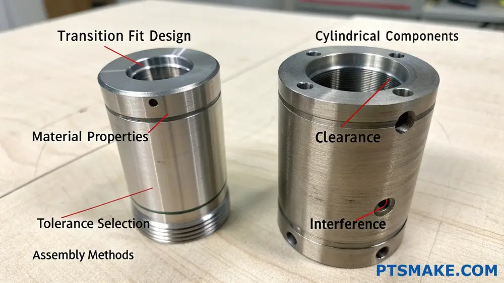
Key Components of Transition Fit Design
- Tolerance Selection
- Material Considerations
- Surface Finish Requirements
- Assembly Methods
Critical Design Mistakes to Avoid
1. Improper Tolerance Calculation
One of the most common errors I see in transition fit design is incorrect tolerance calculation. Engineers often make these specific mistakes:
- Using arbitrary tolerance values without considering functional requirements
- Failing to account for cumulative tolerances in assemblies
- Not considering manufacturing capabilities
Here’s a practical breakdown of recommended tolerance ranges for different transition fit applications:
| Application Type | Recommended Tolerance Range | Typical Use Case |
|---|---|---|
| Light Duty | IT6 – IT7 | Instrument components |
| Medium Duty | IT7 – IT8 | General machinery |
| Heavy Duty | IT8 – IT9 | Industrial equipment |
2. Neglecting Material Properties
Material selection significantly impacts transition fit performance. Common oversights include:
- Not accounting for different thermal expansion coefficients
- Ignoring material hardness differences
- Overlooking material deformation under load
3. Surface Finish Miscalculations
At PTSMAKE, we’ve observed that surface finish plays a crucial role in transition fit success. Key mistakes include:
- Specifying unnecessarily fine surface finishes
- Not considering the relationship between surface finish and assembly force
- Ignoring the impact of surface treatments
4. Assembly Method Oversights
Proper assembly techniques are crucial for transition fits. Common errors include:
- Not specifying assembly instructions
- Failing to consider assembly tools and equipment
- Overlooking the need for special fixtures or alignment guides
Environmental Considerations
Temperature variations can significantly impact transition fit performance. Critical factors include:
- Operating temperature range
- Ambient conditions during assembly
- Storage conditions
Cost Impact of Poor Transition Fit Design
Poor transition fit design can lead to:
Increased Manufacturing Costs
- Higher rejection rates
- Additional machining operations
- More frequent tool replacement
Assembly Issues
- Extended assembly time
- Damaged components
- Higher labor costs
Field Failures
- Warranty claims
- Maintenance problems
- Customer dissatisfaction
Best Practices for Success
Documentation Requirements
Proper documentation is essential for successful transition fit implementation:
- Detailed technical drawings
- Assembly instructions
- Quality control requirements
- Inspection procedures
Quality Control Measures
Implementing robust quality control procedures helps ensure consistent results:
Measurement Protocol
- Proper gauge selection
- Environmental control during measurement
- Regular calibration procedures
Process Control
- Statistical process control implementation
- Regular monitoring of key dimensions
- Documentation of variations
Industry-Specific Considerations
Different industries have unique requirements for transition fits:
Aerospace Applications
- Stricter tolerance requirements
- Special material considerations
- Comprehensive documentation needs
Automotive Industry
- High-volume production considerations
- Cost optimization requirements
- Durability requirements
Medical Device Manufacturing
- Cleanroom assembly requirements
- Biocompatibility considerations
- Regulatory compliance needs
Future Trends in Transition Fit Design
The field of transition fit design continues to evolve with:
Advanced Manufacturing Technologies
- 3D printing capabilities
- Improved surface finishing techniques
- Better measurement systems
Digital Tools
- FEA simulation software
- Tolerance analysis programs
- Digital twin implementation
Real-World Implementation Strategies
Based on my experience at PTSMAKE, successful transition fit design requires:
Early Planning
- Design review meetings
- Prototype testing
- Manufacturing capability assessment
Communication
- Clear technical specifications
- Regular supplier feedback
- Cross-functional team involvement
Continuous Improvement
- Regular process reviews
- Documentation updates
- Team training
Click to learn more about optimal tolerance zones for precision fits in manufacturing. ↩
Click here to learn more about tolerance calculations and their practical applications in manufacturing. ↩
Click here to learn more about tolerance calculation methods and their practical applications. ↩
Click to learn more about clearance and interference fits in mechanical design. ↩
Click here to learn more about interference calculations and optimal fit selection methods. ↩
Click to learn more about clearance calculations and optimal fit selection guidelines. ↩
Click to learn more about calculating proper clearance for optimal mechanical fit design. ↩
Click to learn more about elastic deformation calculation methods and practical applications. ↩
Click to learn more about thermal expansion’s critical role in precision engineering and manufacturing. ↩
Click to learn more about how overlapping tolerances affect assembly success rates. ↩